Creating a Wardrobe detailed drawing, Floor Plan, Kitchen Layout and Column Detail using AutoCad
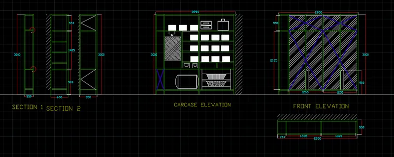
AIM:- Draw the elevation and details of a wardrobe as shown in the Figure below. After sketching, you need to provide the dimensions and text with the use of layers. Use proper text styles and dimension methods to document it. Also, assume dimensions, wherever needed.
Note: All dimensions are in mm.
PROCEDURE:-
- Open a new autocad sheet
- Set the limits of the drawing sheet
- Zoom to be applied to the drawing
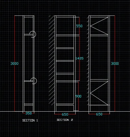
- Draw a sections of 350*3000, 650*3000 and 650*3000
- Then draw a remaining geometry as mentioned in above tool
- Draw tye sections by usimg LINE, OFFSET , TRIM , ARCH and ERASE tool
- The sections are as below;
- Draw te next carcase section as drawn below
- Te case is made by using LINE, offset,trim, hatch, erase etc.
- Draw a section of 3000*2950 then make that section as per requirement using above tool
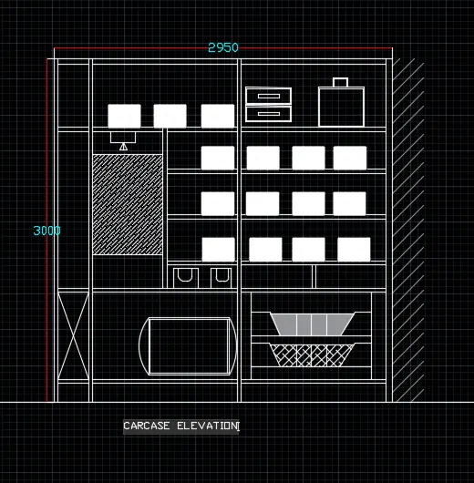
- Draw te next carcase section as drawn below
- The case is made by using LINE, offset,trim, hatch, erase etc.
- Draw a section of 3000*2950 then make that section as per requirement using above tool
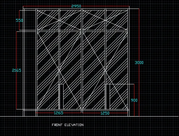
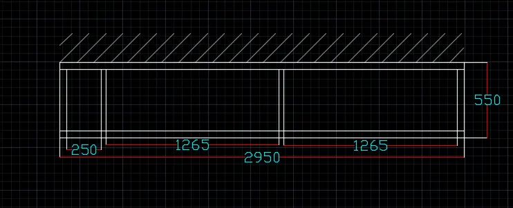
- Give layers to various drawings as shown in below
- Lebelling the drawing
- Dimensioning the drawing
RESULT:-
AIM:- Draw the floor plan as shown in the Figure. Use the proper drafting tools to sketch the plan. Do not hatch or draw the furniture. You need to draw the floor plan with the following:
Note: You can also import the Floor_Plan.pdf into your current drawing and start working on the project. You need to scale the imported pdf file using reference option. All dimensions are in mm.
- Walls (Exterior and Interior)
Wall Thickness: Exterior Wall- 230mm, Interior Wall: 150 mm (Wherever Required)
- Doors and Windows: Assume the size of the doors and window.
2.1 Stairs: Tread-300mm, Riser-150mm
- Insert Text wherever required
- Insert the dimensions using proper dimension techniques
PROCEDURE:-
- Open a new autocad sheet
- Set the limits of the drawing sheet
- Zoom to be applied to the drawing
- In the command line type XLine to involk the Xline and draw in both X and Y directions
- In the command line type OFFSET to involk the offset command and give the offset to the lines wherever required
- In the command line type ADC to find the componenets of plans which required
- Whrever dotted line required used various line types whichg is in the layers
- Used commnasd TEXT to write dimensions and text in tyhe drawing
- The preplan whuch made up till is as below;
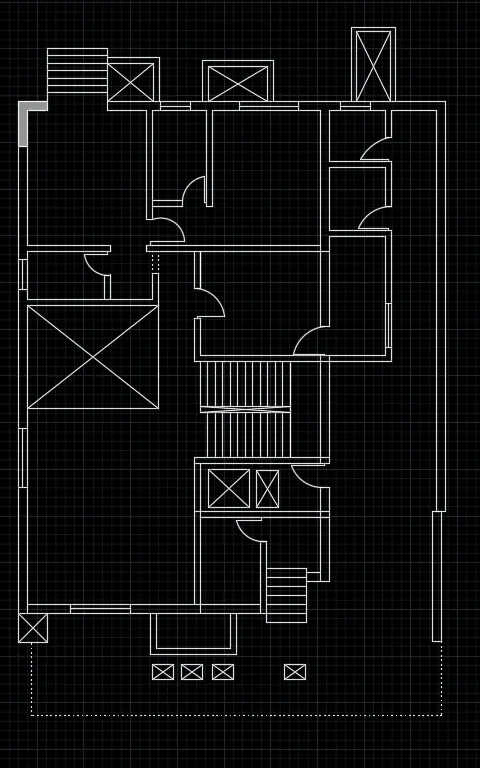
- Now we have to make separate CANOPY , for which we have used CIRCLE, FILLET, LINE , TRIM, ERASE , COPY , MOVE command
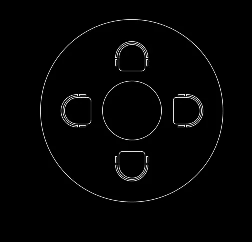
- And placed canopy at its place
- Then make as home decor objects at their place separately
- Make a layers to all the different objects in the drawing, anad take them in diffrents layers
- Finally give dimensions and text to the drawing wherever required in the drawing
RESULT:-
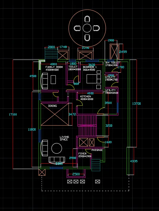
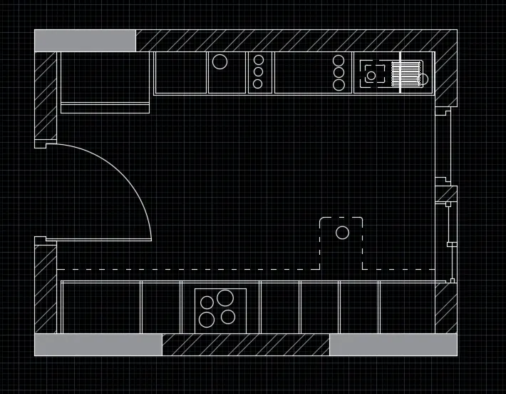
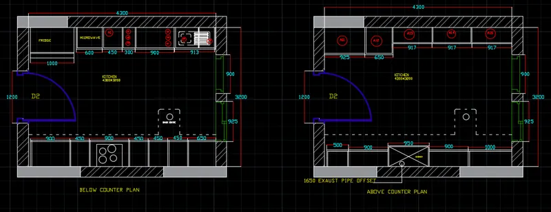
AIM:- Create the Kitchen Layout as shown in the Figure below. Also, use proper dimension techniques to dimension the kitchen layout. Also, insert text wherever required. All dimensions are in mm.
PROCEDURE:-
- Open a new autocad sheet
- Set the limits of the drawing sheet
- Zoom to be applied to the drawing
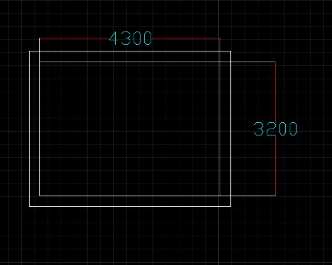
- Draw the rectangle having floor dimensions of 4300*3200
- Give the offset of 250 from the outside
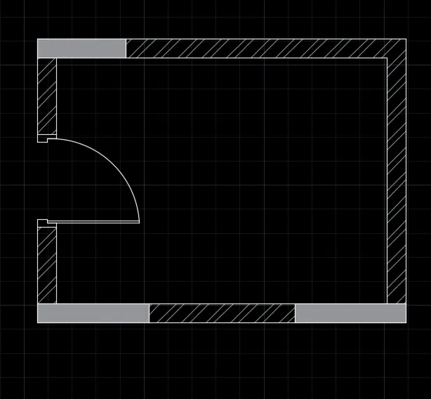
- Draw a door og 1200 wifth using line and arc tool
- Give hatches to the walls as shown below;
- Draw a fridge area of 1000*600 in kitchen 1
- Draw all the essential which are required in the kitchen as shown , the dimension are also according to requirement shown in the figure
- Draw a A11, A12, A13 , A14 and A15 according to required dimensions
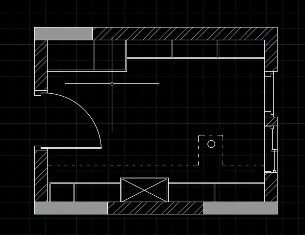
- Draw also chimney portion with precise dimensions
- Draw all the essential which are required in the kitchen as shown , the dimension are also according to requirement shown in the figure
- Lastly, make layers according to types of objects, and give the layers to the objects
- Place the all objects in the specified layers
RESULT:-
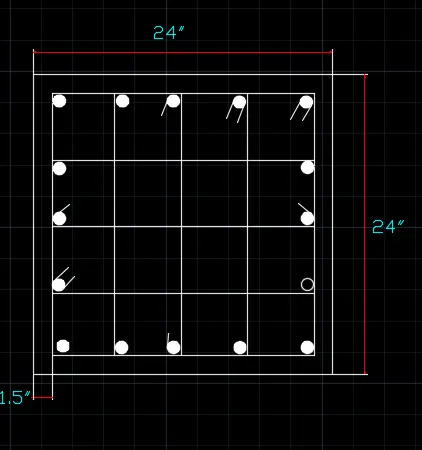
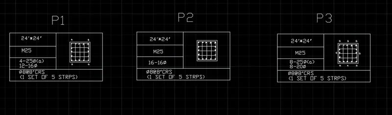
AIM:- Sketch the column details as shown in Figure. Insert dimensions and text in the figure. Refer to the bar sizes from the schedule.
8mm ---- 0.31 Inches
25mm--- 1 inches
16mm—0.62 inches
PROCEDURE:-
- Open a new autocad sheet
- Set the limits of the drawing sheet
- Zoom to be applied to the drawing
- Column P1,P2,P3 to be draw separately
- P1 is as below with the reinforcement and its precise dimensions;
- Similarly draw the other remaining two columns separately
- Then with the of TABLE tool draw three tables separately, and make the table as per requirement with the help of merge etc.
- In those table with the help of MULTILINE TEXT,SINGLE TEXT, COPY tools write the text
- Then apply scale to the previoulsy separate drawn columns and make them of a size which perfectly fits in the table
- Lastly, put them in the table.
RESULT:-
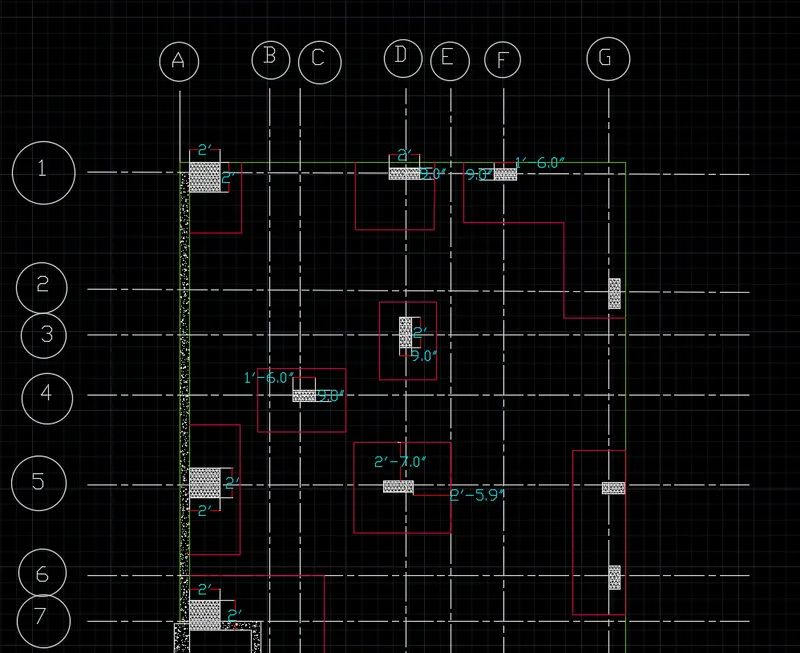
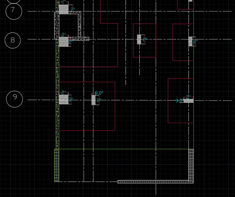
AIM:- Draw the Raft Layout as shown in the Figure. Assume the column size as per your knowledge. You can take the sizes as: 24”x24”, 9” x 24”, 9” x 18”, and 9’ x 24”. You can import the raft_foundation.pdf to ensure the missing dimensions.
PROCEDURE:-
- Open a new autocad sheet
- Set the limits of the drawing sheet
- Zoom to be applied to the drawing
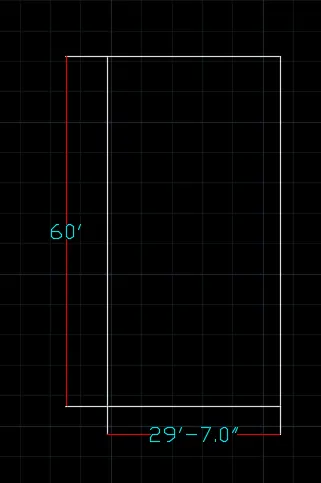
- Take a rectangle command to draw rectangle of 60'*29'7"
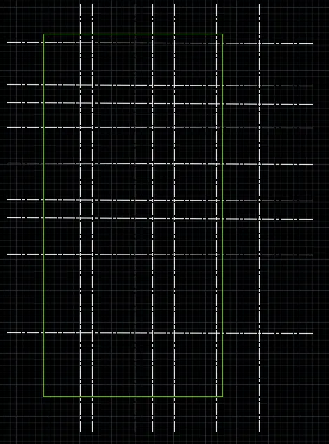
- Take a reference as a rectangle and draw a dotted lines as below shown.
- With the help of dotted lines and offset command the grids are drawn.
- Draw a columns of a dimensions 9'*24',9'*18',24'*24'.
- With the help of hatch give hatches to all columns
- Give hatches to other objects also as per requirement
- Give grid line a label with the help of circle and text tool
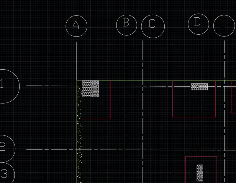
- The preplan without dimensions are as below
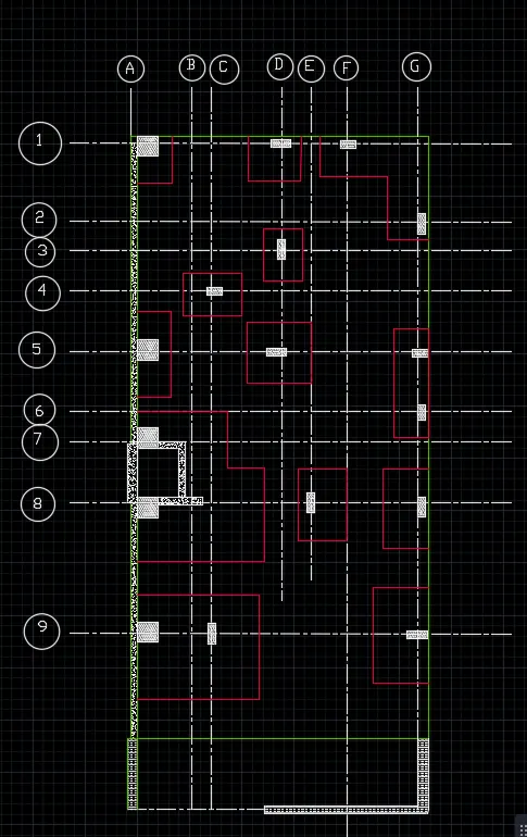
- Give dimensions to the all the plan with the help of MTEXT
- Lastly give layers to all the diffrent objects in the drawing, and take respective objects in the diffrent layers
RESULT:-