Creating a Residence Layout, Seating plan, Toilet and Utility room plan using AutoCad
1. Residence Plan:
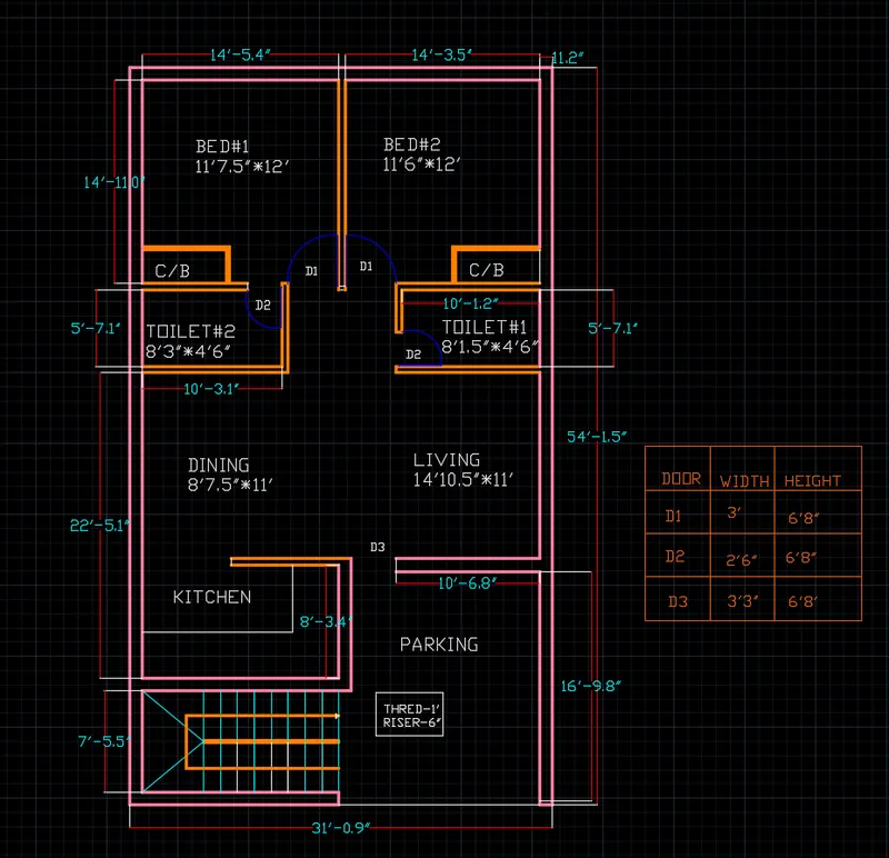
Sketch the layout of a residence as shown in the Figure 1. Consider all dimensions as reference to sketch the unit plan. Also the text in the layout are only for reference. Assume the missing dimensions. Also, refer the schedule for size of the doors.
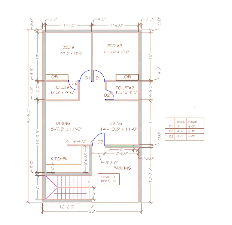
AIM :- DRAWING A ABOVE RESIDENTIAL PLAN IS AS FOLLOWS;
INTRODUCTION:-
- House plan is a set of construction or working drawings (sometimes called blueprints) that define all the construction specifications of a residential house such as the dimensions, materials, layouts, etc
COMMAND USED;-
- Line command
- Offset command
- Unit command
- Fillet command
- Trim command
- Erase command
- Limmax command
- Arch tool
- Limits command
- Zoom command
- Extend command
- Line weight command
- Dimstyle command
- Dimlinear command
- Text command
- Xline command
- Ortho
- Object snap
- Layer tool
PROCEDURE:-
- Enter the XLINE command to involk it and draw xline in the x and y directions
- Make offset of 0.9' and draw the exterior wall
- The main wall is of 0.9' thick
- The interior wall is of 0.45' thick
- Then by selecting OFFSET command , give all thye exterior and interior line offset of 0.9' and 0.45'
- With the help of trim trim all the unwanted objects
- Line which are unwanted and not trim by "TR " command , trim them ERASE command
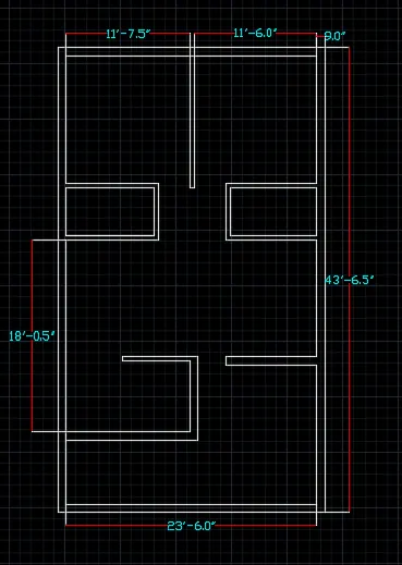
- Form the interior walls and exterior with help of offsets and fillet arn trim etc.
- The result is as below;
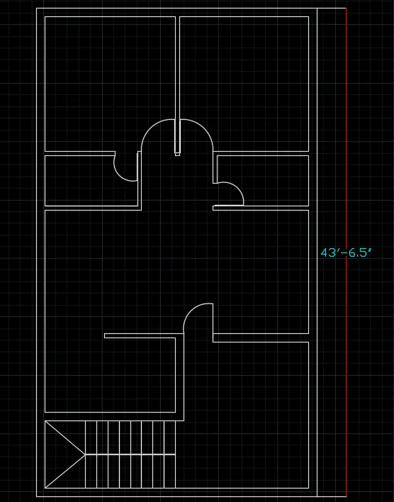
- Draw doors D1,D2 and D3 with helps of command line , offstet and circle ( 2 points)
- Draw a staircase with the help of offsets of thread 1' and riser 6"
- Erase and trim unwanted objects with the help od command-trim and erase
- Give LAYERS to the various objects like we give pink colour to exterior walls and so on.
- Give dimensions to the plan with the help of DIMLINEAR command
- Give text to the the drawing with the help of TEXT command
RESULT:-
DRAWING A ABOVE RESIDENTIAL PLAN IS AS FOLLOWS;
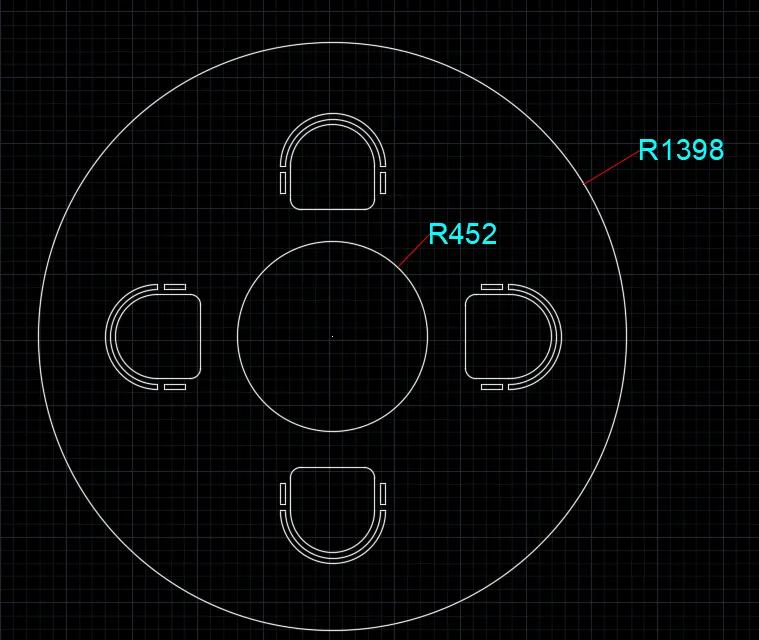
2. Sketch the seating plan for an outdoor canopy. Assume the dimensions for the seating. Also, consider the dimensions in mm.
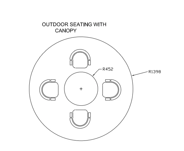
AIM :- DRAW A SEATING PLAN FOR AN OUTDOOR CANOPY
INTRODUCTION:-
Canopy is an overhead roof structure that has open sides. Canopies are typically intended to provide shelter from the rain or sun, but may also be used for decorative purposes, or to give emphasis to a route or part of a building.
COMMAND USED;-
- Line command
- Unit command
- Fillet command
- Trim command
- Erase command
- Limmax command
- Limits command
- Zoom command
- Dimstyle command
- Dimlinear command
- Ortho
- Object snap
- Arch tool
- Offset command
PROCEDURE:-
- Set units for the drawing with the help of UNIT command
- Set a limits with the help of LIMMAX command
- Press ZOOM -enter and ALL enter to visualized purpose
- Give "c" command to the command line to involk the CIRCLE command
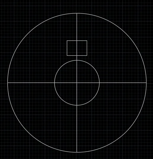
- Draw a circle of radius 1398 and radius 452 from the same centre
- Draw a line from the centre of circle to the circumference of the circle, these lines area acts as reference lines for the drawing precision.
- Draw ac recatngle by usings line command in between two circles
- results as of:
- With the help of offset command give offset to rectangle both right and left side twice
- Below of seat, give fillet of 50 radius and cornered it with 50 degree
- On upper portion , using ARCH command (start , centre, end ) arrange all the arch as shown in drawing
- Trim all unnecessary objects in figure with the help of TRIM command and erase with ERASE command
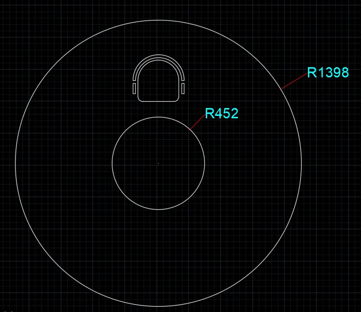
- Now, with help of MOVE and ROTATE commands placed the seat object as requirement.
- Give dimensions to drawing with the help of dimension tool
RESULT:-
Seating plan for an outdoor canopy;
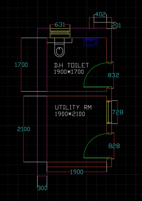
3. Sketch the part plan for the toilers and utilities room. Consider the outer wall thickness as 300mm and inner wall thickness as 150mm. Also, assume the missing dimension, Texts, dimensions, and hatches are only for references. Also, symbols for toilets and w/c are also for references.
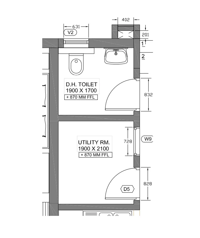
AIM :- DRAW THE PART PLAN FOR THE TOILERS AND UTILITIES ROOM
INTRODUCTION:-
A toilers is santiziing area in the house structure with include bath, and w/c . and a utility room is a room in a house which is usually connected to the kitchen and which contains things such as a washing machine, sink, and cleaning equipment
COMMAND USED;-
- Line command
- Unit command
- Fillet command
- Trim command
- Erase command
- Limmax command
- Limits command
- Zoom command
- Dimstyle command
- Dimlinear command
- Ortho
- Object snap
- Arch tool
- Offset command
PROCEDURE:-
- First give LIMMAX Values to the sheet
- Then set the units with the help of UNITS command
- Give XLINE command to the command line to involk the construction line
- Draw xline in horizontal and vertical directions
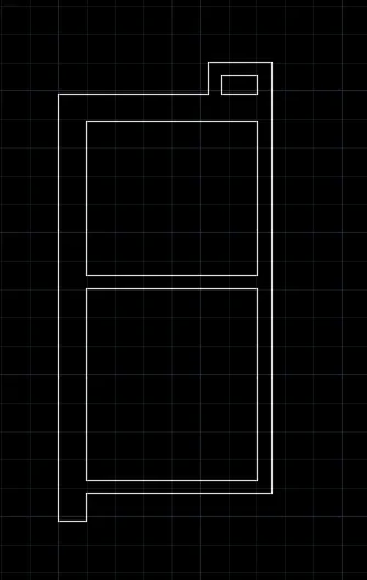
- Make thick wall of 300 and thin wall of 150
- With the help of OFFSET make all the walls
- Trim and erase all the unwanted object in the drawing
- Result is as below;
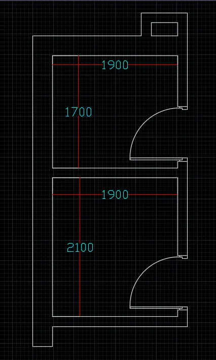
- Make the doors with presions with the help of offset. trim , line and arch
- The result is;
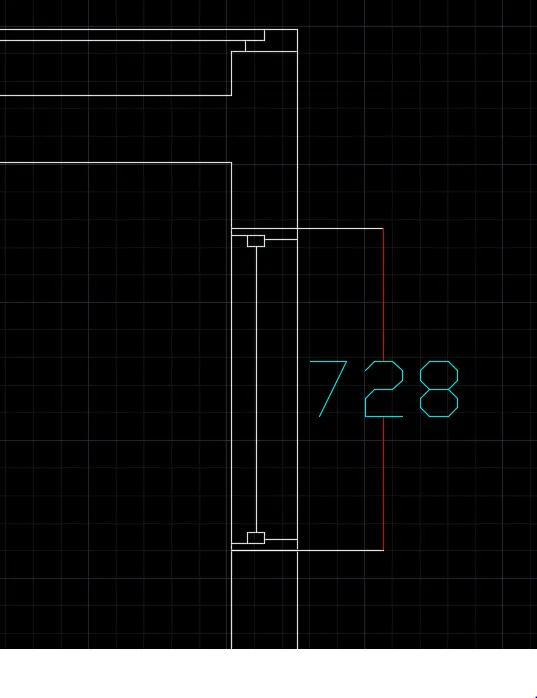
- Make the window with precision and it created as below
- Commands used are offset,line ,trim
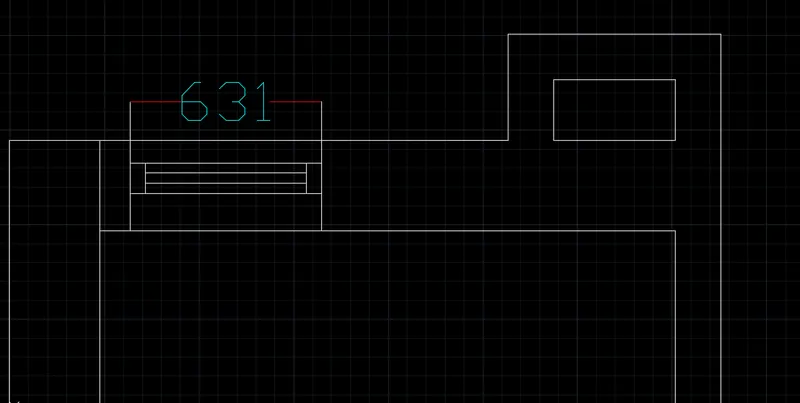
- The second windoe is created
- Cmmand used are line, offset, trim
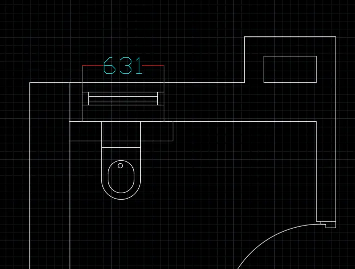
- The commod is created
- Command used are line,offset,fillet,circle and trim
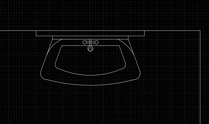
- Wash basin is created
- Command used are line , offset, arch, fillet and trim
RESULT:-
PART PLAN FOR THE TOILERS AND UTILITIES ROOM;