Creation of Column Schedule and Drawing Template using AutoCad
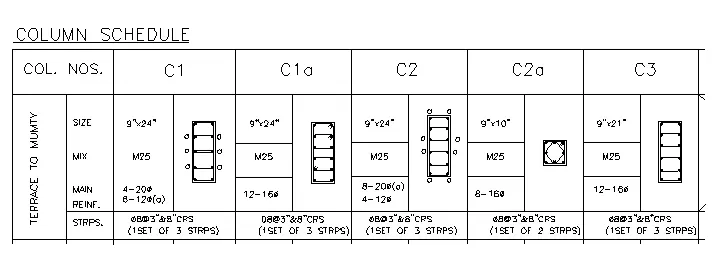
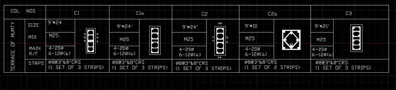
1. Create a column schedule as shown in the figure.
INTRODUCTION:-
- In this projects we have to make column schedule in autoCAD .
- Structural columns are identified in a column schedule by intersecting grid lines and by their top and bottom constraints and offsets. They are placed into the column schedules according to these identifications.
PROCEDURE::-
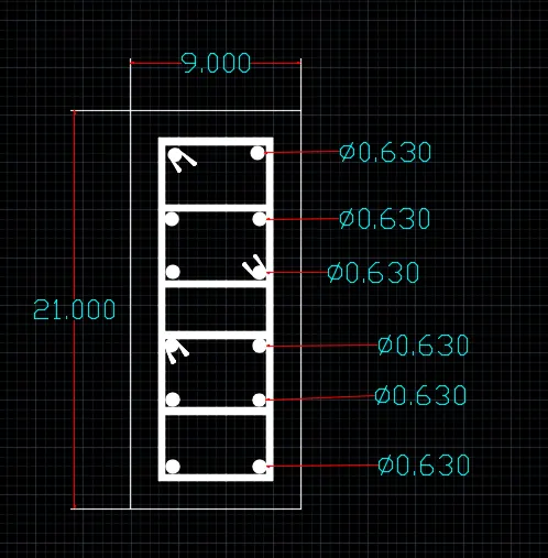
- Make below 5 columns details with the help of tool in autoCAD
- Command used are;
- Offet command
- Line command
- Rectangle command
- Circle command
- Trim command
- Hatch command
- Erase command
1. C1
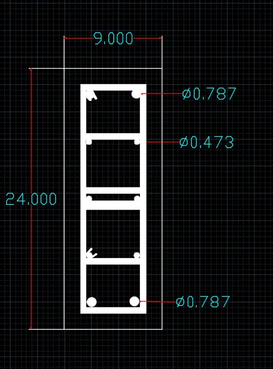
2. C1a
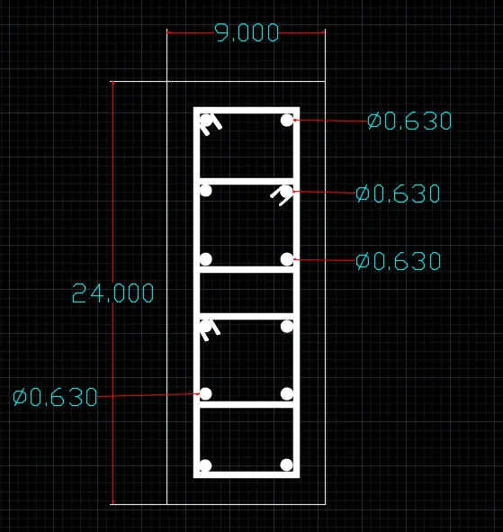
3. C2
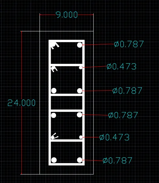
4. C2a
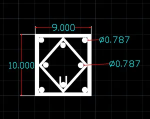
5. C3
- Now, for makiing tables of column scheduling,use command TABLE, TABLESTYLE, TABLEEDIT, TEXT ETC
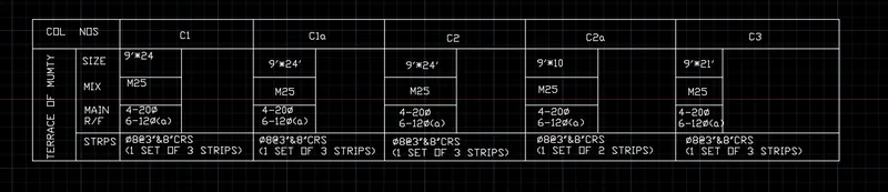
RESULT:-
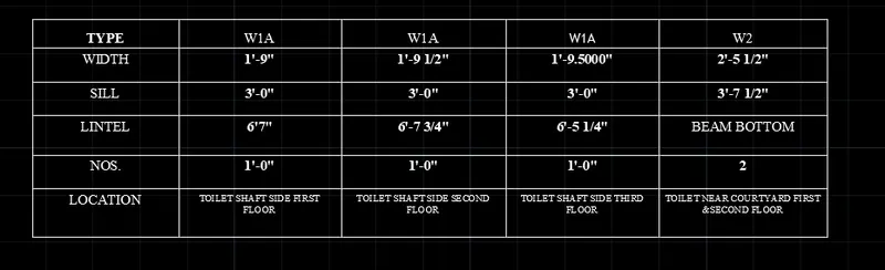
2. Create a window schedule as shown in the figures:
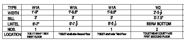
Window Schedule:
INTRODUCTION:-
- The table contains the width, lintel height, sill, their numbers and respective locations for different types of beams
PROCEDURE:-
- Select the TABLE command and make the required table with rows and columns
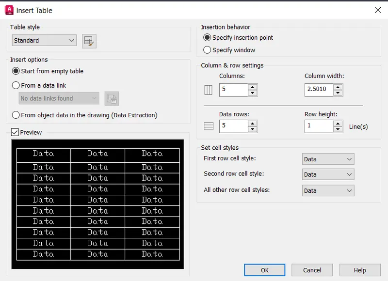
- Make the table as follows;
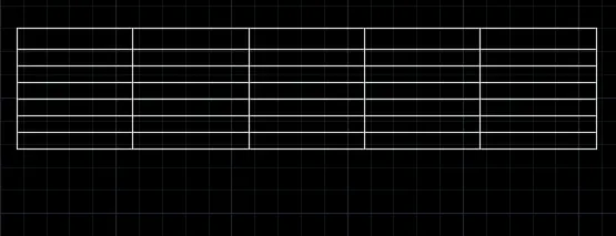
- With the helps of tools-text, table style and table edit make the below table.
RESULT:-
3. Create the drawing template as shown in the figure:< Use the Notes as in the figure>
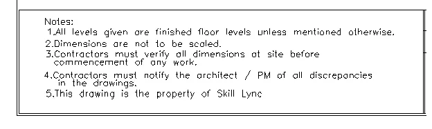

PROCEDURE:-
- Open new autocad sheet to draw a table
- Select the TABLE command and make the required table with rows and columns
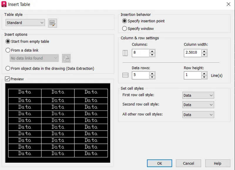
- The core column and rows as below , which we can be edited in further table creation

- Using MERGE tool we a created the require table as below shown;

- Drawing which can be put on the first column are as below;
- We created this column by using MULTILINE TEXT tool
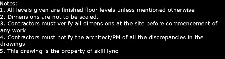
- Lastly , write all the require text
RESULT:-

4. Create the list of drawing schedule as shown in the figure:
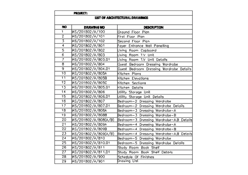
PROCEDURE:-
- Open a NEW drawing in the autocad
- Select the TABLE command and manage all the columns and rows as shown oin the snap;
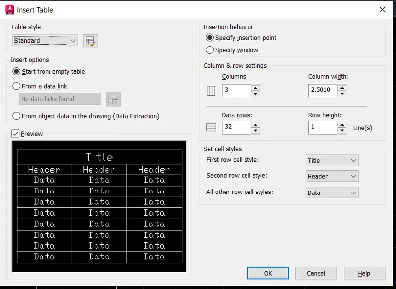
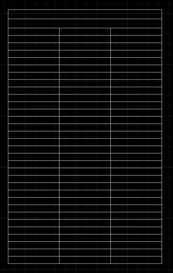
- The form table is as below;
- Give cppmmand TABLESTYLE to give various fonts, fonts size and location of text etc .
RESULT:-
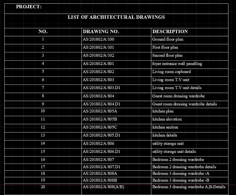
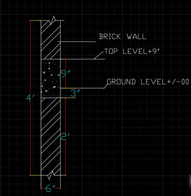
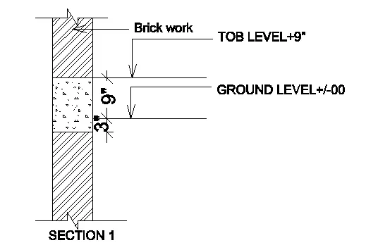
5. Create the Beam detail as shown in the figure and provide text wherever given.
PROCEDURE:-
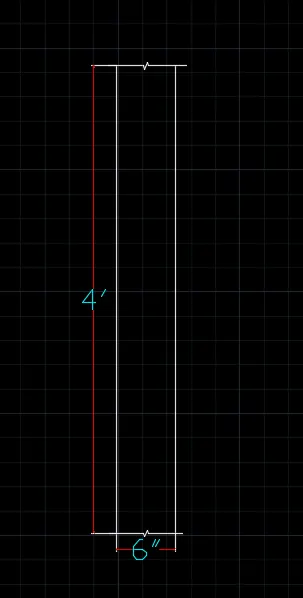
- Select a LINE command , and draw a line of 4' vertically
- Draw a parallel line to to the same line apart distance of 6"
- Select a BREAKLINE command to draw a breaklines up and below
- Results is as up now;
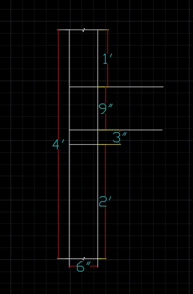
- Draw a offset of 1' from above
- Draw a offset of 9" to the line
- Draw a offset of 3" to the line
- So that 2' distance line remains from the bottom
- Result is as of now;
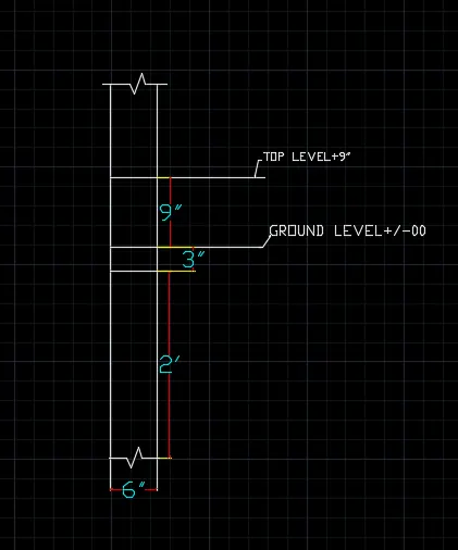
- Write test using MULTILINE TEXT
- Used LEADER arrows for the declaration or text
- Using HATCH tool , give hatches to various areas
- Hatching given to the brickworks and concrete area
RESULT:-
Beam detail is as below;