Week 2 Challenge
Q1.
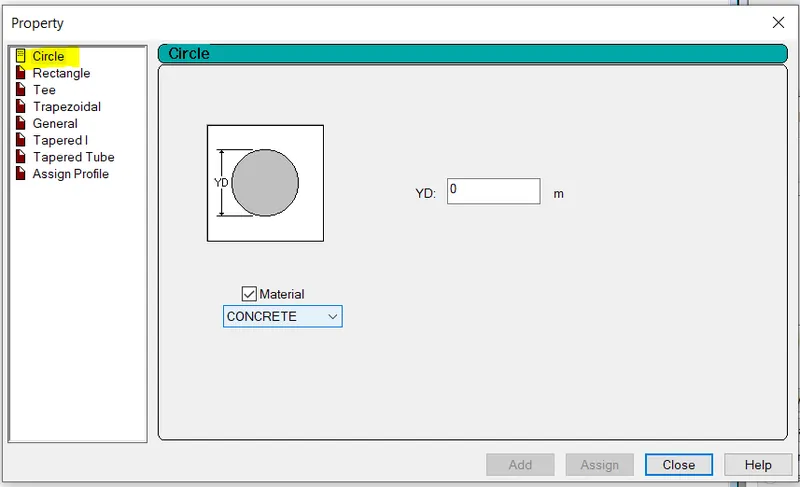
1. How will you assign Circular section to column?
AIM:
To assign Circular section to column
INTRODUCTION:
Columns are defined as vertical load-bearing members supporting axial compressive loads chiefly. This structural member is used to transmit the load of the structure to the foundation. In reinforced concrete buildings beams, floors, and columns are cast monolithically. The bending action in the column may produce tensile forces over a part of cross-section. Still, columns are called compression members because compressive forces dominate their behavior.
PROCEDURE:-
- Create the model in the STAAD Pro that can be a column
- Go to properties in that define parameters
- Assign the circular shape of the column
- The radius of the circular is given
RESULT:-
The Circular section to column is assigned sucessfully
2. How will you assign Unit system to a .std model file?
PROCEDURE:-
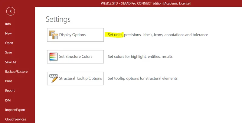
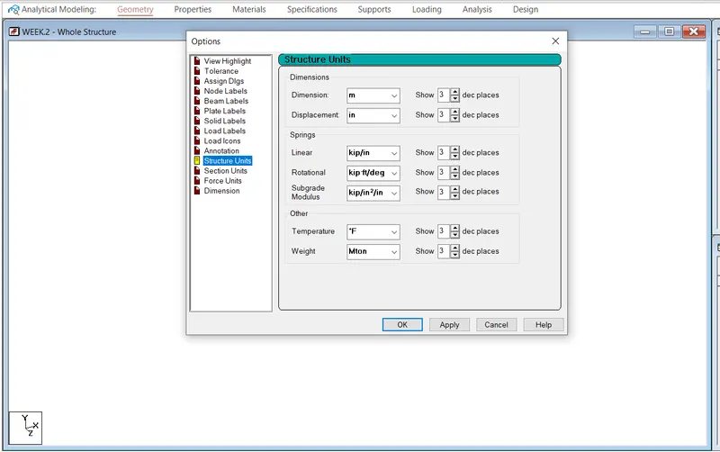
To assign the unit system in the STAAD pro
- Go to the file menu and then the settings
- Open the structural settings
- Change the dimensions to the required units
3. What are the parameters to be specified while using “Bay Frame” option?
ANSWER:-
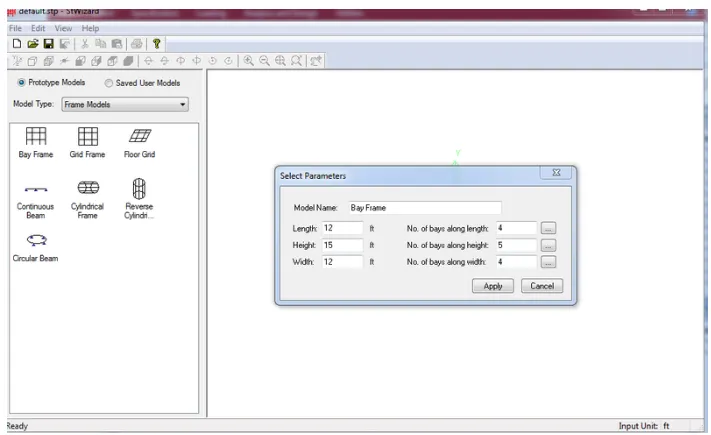
To create the parameter of the design by Bay frame
- By clicking on structural wizard option
- Click frame model and the bay frame
- Enter the parameters like length, breadth, height and the bay frame along the length, breadth and height
4. Name few codal standards incorporated in STAAD Pro software.
ANSWER:-
In STAAD pro the Codal standard are incorporated for the steel, Concrete, Aluminum
For the codal provision incorporated in STAAD pro are ;
- IS 456-2000
- IS 13920-2016
- IS 875-1987
- IS 800-2007
- IS 1893-2016
5. How will you specify the design compressive strength for a RCC section?
ANSWER:-
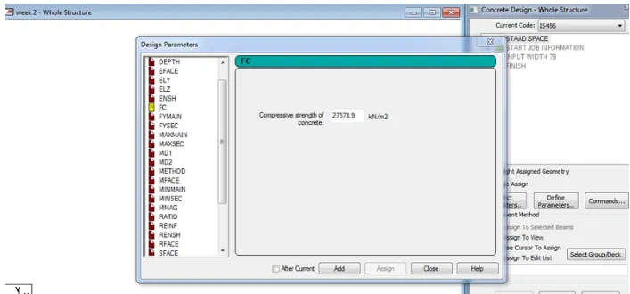
- Go to the Design option
- Click on the define parameter
- IN the design Parameter the Fck Compressive strength of RCC section is Given as 25000KNm
Q2.
1. State the “Input” steps involved in RCC design.
PROCEDURE:-
1. GEOMETRY:-
The node location and the node spacing are given
2. PROPERTIES:-
Specify the sectional properties of the section
3. MATERIALS:-
Specify the properties of the materials
4. SPECIFICATION:-
The specification are given
5. SUPPORT :-
The end support are to be given as per necessity
6. LOADING:-
Need to provide the loading pattern and the loading combination
7. ANALYSIS:-
Need to analyse the model and all the input specifications are given
8. DESIGN:-
Finally the design are to be done
2. Explain the difference between Fixed and Enforced support condition in STAADPro.
ANSWER:-
Fixed Support degrees of freedom which are to be treated as fully restrained, Hence, those degrees of freedom are not considered for the stiffness matrix, and their value is not calculated.
But in Enforced degrees of freedom which are free to displace are assigned springs of zero stiffness. Hence, for all the 6 degrees of freedom at such supports, the displacements are calculated.
Q3.
1. Explain the steps involved in analysis of a model using STAAD Pro sequentially.
ANSWER:-
Steps involved in the of a model using STAAD Pro sequentially are as follow;
- Create model using node system or create by using the structural wizard
- Add beams
- Choose properties
- Add supports
- Add specificaton if any
- Add loadings
- Apply perform analysis
- Run the MODEL
- Goto post processing
- Note DISPLACEMENT SHEAR FORCE AND BENDING MOMENT
2. Explain the two ways in which a structural framework/model can be created in STAAD Pro software.
ANSWER:-
- By Analytical Model
- By Physical Model
STAAD.Pro Physical Modeler takes advantage of physical modeling to simplify of modeling a structure, which in turn more accurately reflects the process of building a model. Beams and surfaces are placed in the model on the scale of which they would appear in the physical world.
3. Elaborate the different support conditions in STAAD Pro.
ANSWER:-
The various types of the supports available in the STAAD pro are as follows;
1.FIXED:-
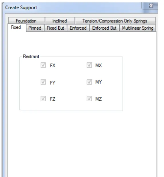
All the transitional and rotational displacement are restrained
2. PINNED:-
Transitional displacement are restrained but rotational oments are not restrained
3. FIXED BUT:-
The fixed support is similar to pinned support it allows us to provide the degree of freedom to view the displacement either translation or rotational
4. ENFORCED:-
When enforced supports are assigned to the structure the software allows the springs to itself and the displacement can be calculated however there is no provision to provide the spring constant
5. ENFORCED BUT:-
The software assigns the spring itself with zero stiffness or high stiffness
4. How will you extract the stress distribution for a staircase slab?
ANSWER:-
procedure of extract the stress distribution for a staircase slabs is as below;
- After Analyse go to the Postprocessing
- Select Load Combination
- Click on Plate Results.
- Select Plate Sress Contour
- Select LOad Combination.
- Check MAx Absolute Stress
- Check Major Principle Stress
- Check MX(Local)
5. Explain the different ways to view SFD & BMD in STAAD Pro.
ANSWER:-
Way of view SFD & BMD i STAAD pro is as below;
- After Analysis
- Go to PostProcessing
- Check SFD and BMD by Click on SFD and BMD tool.
- Next Click on LAyout and click on Graph to view SFD and BMD
- By Double click on Member.
Practical
1. Analyze the following structural elements and validate the results
A. Simply Supported Beam
a. A Simply supported beam with two point loads symmetrically placed
b. Span L = 20m
c. Load P = 50kN each
d. Both P located at 5m from each support
B.Fixed Beam
a. Span L = 16m
b. Uniformly Distributed Load w=9kN/m
PROCEDURE:-
- Open Stadd Software
- Create new Model
- Select Matric
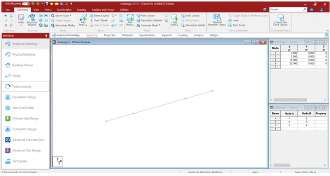
- Go to the Geometry and give ditance of 0-20 m in Table
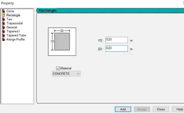
- Go to property and add property of beam
- Choose rectangle and material concrete.
- Assign the Property to the view.

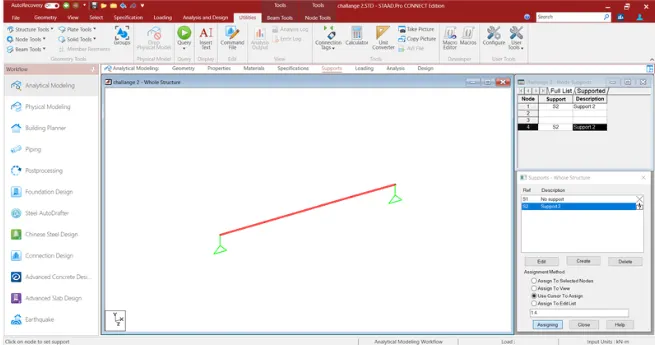
- Go to the support
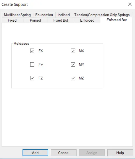
- Create support
- Create Support as simply supported (Only Restraint at Fy)
- Go to the Loading Tab
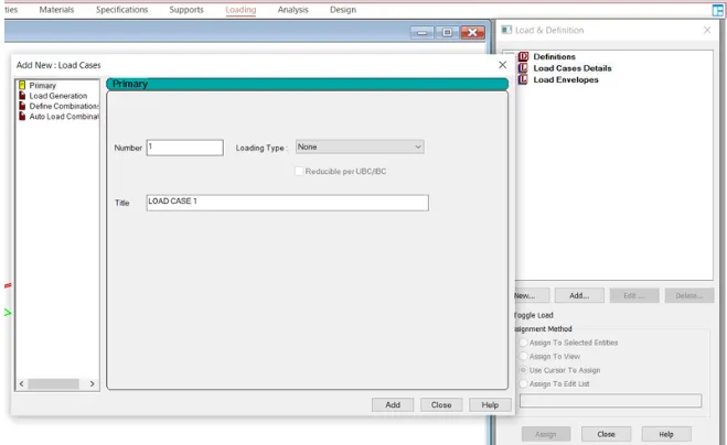
- Click on Load Case Details
- Add Load case
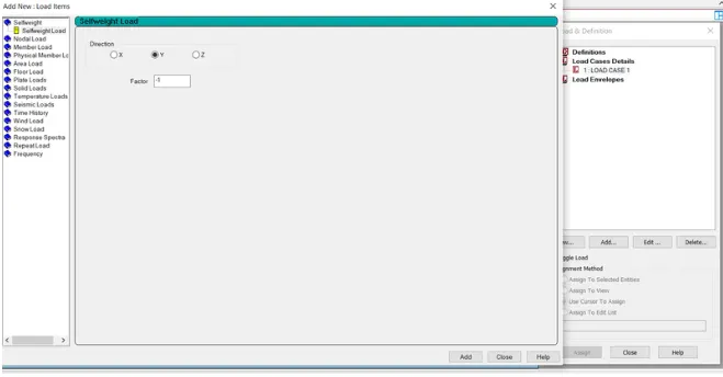
- Add Self Weight
- Agian click on Load case
- Click on Member Load
- Add concentrated Load of 50 KN at the distance of 5 and 10 m.
- Now add the Load
- Assign the Load to the Member
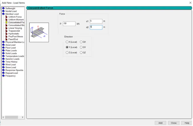
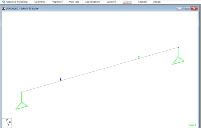
- Now To go Assign Tab
- Click on Define Command And Add Perform Analysis
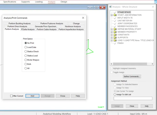
- After Analysis Go to PostProcessing
- Click on Load Case
- Check SFD, BMD and Displacement
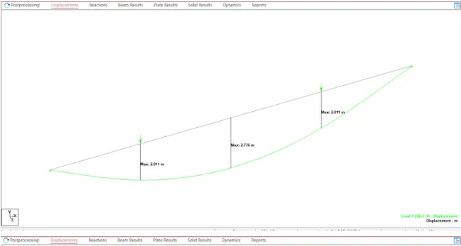
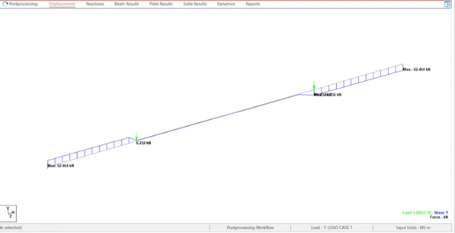
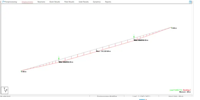
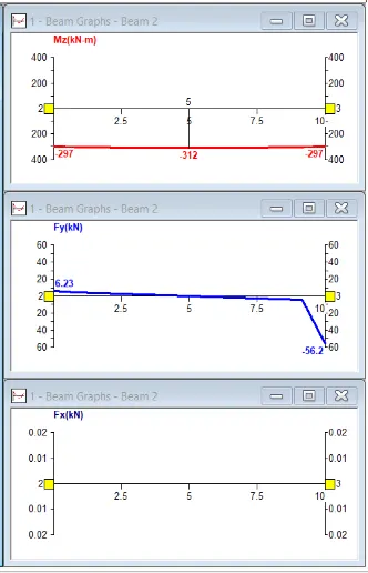
Max BMD = 312
Max SFD = 62
Max Displacement = 2.776
B.Fixed Beam
a. Span L = 16m
b. Uniformly Distributed Load w=9kN/m
Ans:
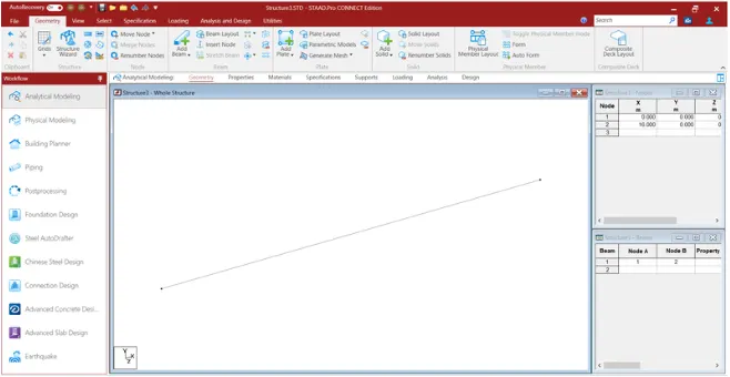
- Go to the geometry
- Add Length of 16 m in X in table
- Go to the Property Tab
- And Property as Rectangle and material as concrete
- Assign the Property
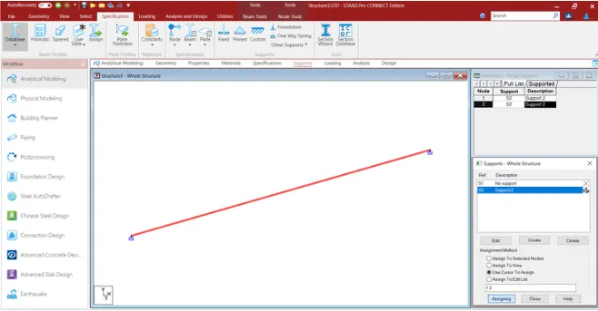
- Go to the Support Tab
- Add Support as Fix
- Assign the Support
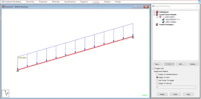
- Go to the Loading
- Click on Load Case
- Add Load case
- Add selfe weight
- Click on Member Load and add Uniform Load of 9 KN/m
- Assign the Load
- Now Analyse the model
- Click on Define Command
- Run Analysis
- After Analysis Go to the PostProcessing
- Add Load case
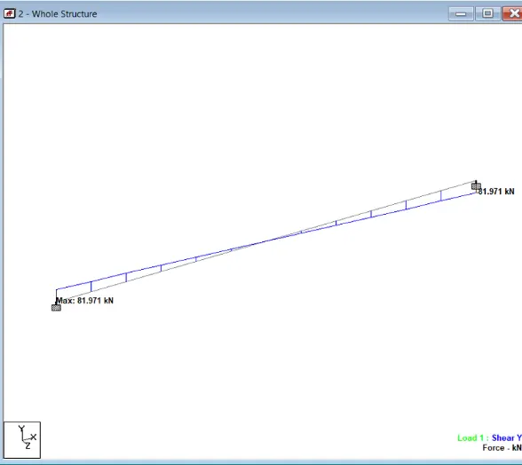
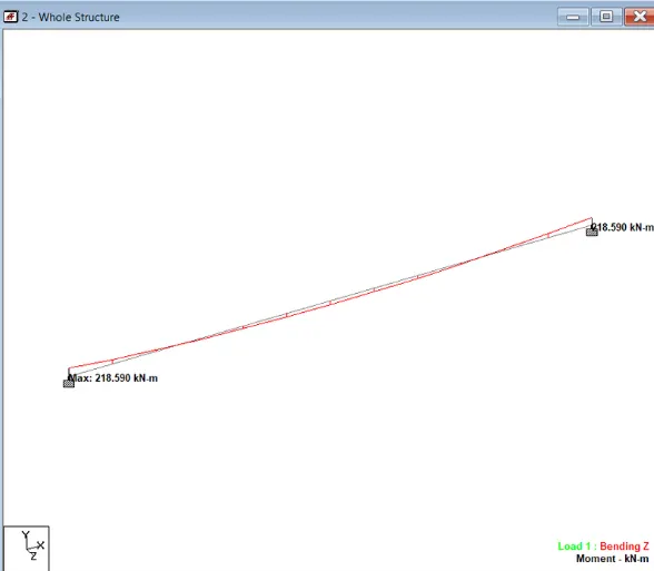
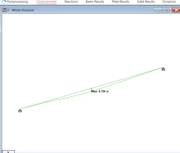
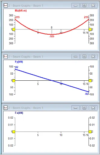
- Check SFD, BMD and Displacement.