Calculation of Stiffness in Structural elements
AIM:- Calculation of Stiffness in Structural elements
INTRODUCTION:-
- In structural engineering, the term 'stiffness' refers to the rigidity of a structural element. In general terms, this means the extent to which the element is able to resist deformation or deflection under the action of an applied force
- In this assignment we try to solve the values and behaviour of the same
Question 1:
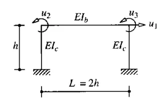
Compute lateral stiffness of the one story frame with an intermediate realistic stiffness of the beam. The system has 3 DOFs as shown. Assume L = 2h and Elb = Elc
AIM:-
Compute lateral stiffness of the one story frame with an intermediate realistic stiffness of the beam. The system has 3 DOFs as shown. Assume L = 2h and Elb = Elc
INTRODUCTION:
Lateral Stiffness
The ability of a body to resist lateral deflection when a lateral force is applied. This is also called as Storey Stiffness, wherein the lateral deflection is storey drift and lateral force is storey shear.
ANSWER:-
CASE 1:-
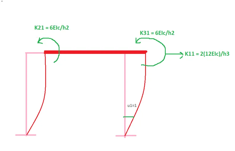
- Unit displacement u1=1,u2=0,u3=0
- Stiffness coefficiant of column translation (2 similar) = 2 x 12EI/h^3
- Stiffness coefficiant of beam rotation (2 ends) = EI/h^2
Therefore;
CASE 2:-
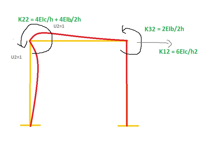
- Unit rotation u2=1,u1=0,u3=0
- Stiffness coefficiant of column rotation at right end = 6EI/h^2
- Stiffness coefficiant of column + Beam rotation at left end = 4EI/h + 4EI/L where L = 2h as given
= 4EI/h + 4EI/2h
= 6EI/h
Therefore;
CASE 3:-
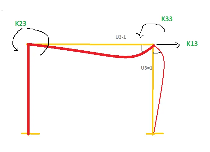
- Unit rotation u3=1,u1=0,u2=0
- Stiffness coefficiant of column rotation at left end = 6EI/h^2
- Stiffness coefficiant of column + Beam rotation at right end = 4EI/h + 4EI/L (where L = 2h as given)
= 4EI/h + 4EI/2h
= 6EI/h
Therefore;
As, Elb = Elc
k*u = fs
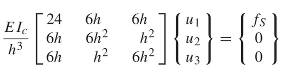
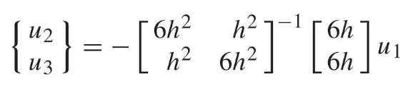
By applying static condition method, we are deducing the 3 unknown expression into 2 unknown equation.
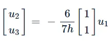
from the second and third equation, the joint rotation can be expressed in terms of lateral displacement as follows :
substituting above equation into the first of three in equation gives
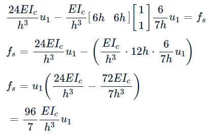
Where, k = `96/7 ( Elc)/h^3`
Therefore, the lateral stiffness coefficient k is obtained.
Question 2:
AIM:- For the following structures:
- Determine the number of degrees-of-freedom for dynamic analysis
- Establish the equation of motion
- Calculate their natural frequencies
INTRODUCTION:-
Structural dynamics is a type of structural analysis which covers the behavior of a structure subjected to dynamic (actions having high acceleration) loading. Dynamic loads include people, wind, waves, traffic, earthquakes, and blasts. Any structure can be subjected to dynamic loading. Dynamic analysis can be used to find dynamic displacements, time history, and modal analysis.
ANSWER:-
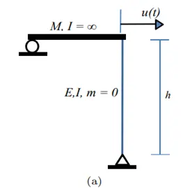
a)
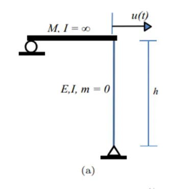
- Position of the element can be described by 1 coordinate only u(t)
- The system has single degree of freedom structure
- The column has fixed end at bottom. So the stiffness coefficient will be as follow
k = `(3EI)/h^3`
The equation of motion shall be;
Mu + ku = 0
Natural frequency formula;
ω =`√k/m`
= `√((3EI)/(Mh^3))`
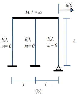
b)
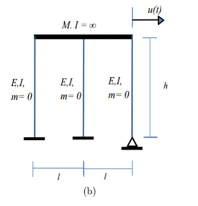
- Position of the element can be described by 1 coordinate only u(t), because beam with infinite stiffness will induce uniform translation in all columns.
- The system has single degree of freedom structure
- Two columns with both end fixed and one column has pinned-fixed ends. So the stiffness coefficient will be as follow
k1 = `(12EI)/h^3`
k2 = `(12EI)/h^3`
k3 =`(3EI)/h^3`
For parallel stiffness elements,
ke = (k1+k2+k3) = `(27EI)/h^3`
The equation of motion shall be
Mu + ku = 0
Natural frequency formula
ω =`√k/m`
= `√(27EI)/(Mh^3)`
Question 3:
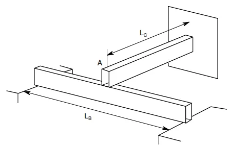
Consider the propped cantilever shown in the figure below. The beams are made from the same steel section and have lengths as shown on the diagram. Determine the natural period of this system if a large mass, M, is placed at the intersection of the beams at point A. The weight of the beams in comparison with the mass M is very small.
AIM:
To consider the propped cantilever shown in the figure below. The beams are made from the same steel section and have lengths as shown on the diagram. Determine the natural period of this system if a large mass, M, is placed at the intersection of the beams at point A. The weight of the beams in comparison with the mass M is very small.
INTRODUCTION:
The ability of a body to resist lateral deflection when a lateral force is applied. This is also called as Storey Stiffness, wherein the lateral deflection is storey drift and lateral force is storey shear.
ANSWER:-
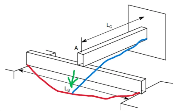
1. Effective stiffness of the system ;
Ke = Kb+Kc
KB = `(48EI)/(lb^3)`
Kc = `(3EI)/(lc^3)`
ke = `3EI (1/(Lc^3) + 16/(Lb^3))`
Natural frequency formula;
ω = √ k/m
ω = √3EI(1/Lc^3 + 16/Lb^3)/M
TIME PERIOD ( T )= `(2π)/ω`
Question 4
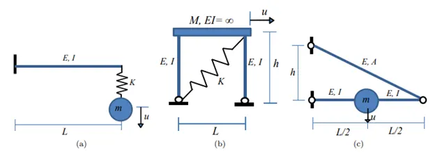
Determine an expression for the effective stiffness of the following systems:
AIM:-
Determine an expression for the effective stiffness of the following systems:
INTRODUCTION:
We can redefine stiffness as the ability of a material to distribute a load and resist deformation. From this, we can get understand that stiffness depends on Forces and Deformations.
a)
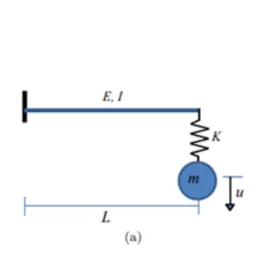
- In the figure (a) we can see there is a cantilever beam which has a supspendend mass "m" at the unsupported end.
- To find the stiffness of the beam:
- The stiffness coefficiant of the spring is K
- Stiffness of the beam;
k1 =`( 3EI)/l^3`
- Stiffness of spring;
k2 = K
ke = `1/(k1) +1/(k2 )`
= `(3EIK)/( KL³ + 3EI)`
b)
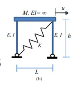
- In the figure (b) we can see a frame of two columns and a beam having DOF as 1.
- A spring is attached diagonally.
- For effective stiffness of the whole frame:
- Stiffness for both columns;
k1 =``(6EI)/h^³``
- As mentioned the stifness of the spring is K but we need to find the inclined stiffness.
P =`p/cosθ`">θθ
U = ucosθ">θθ
K= kcos²θ">θθ
- Now cosθ">θθ = h/ ">√( l² + h² )
K = `(k*h²)/( l² + h² )`
K = P/U
ke = `k1 + K`
= `(6EI)/h^³ + (k*h²)/( l² + h² )`
c)
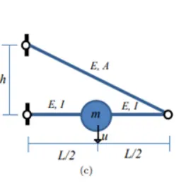
- In the figure (c) we can see that there is a series connection of two beams, of which one is inclined.
- Stiffness of the horizontal beam;
k1 = `(48EI)/L^³`
- Now for the inclined component;
-
force acting at the right end is mg/2 and deformation caused by the strut at the point of 'm' is half of its right end nodal deformation.
- There will be two components of that, one is vertical and the other one will be horizontal.
`(Mg)/2`= ``Kea.vert *2*[delta 2]`
`(Mg)/(delta 2`= 4 Kea.vert
K2 = 4 Kea.vert
we assumed vertical axial stiffness in our calculation but we have an inclined axial stiffness in the given system;
so we have resolve Kea,vert in Kea only
k2 =`( 4Kea * h²)/ ( L² + h²)`
`1/(ke) = 1/(k1) + 1/(k2)`
`( 1/((48EI)/L^3) ) + ( 1/( 4 kea h2/(L2+h2) ) ) = ( (1)/((48EI)/L^3) ) + ( 1/( (4EAh2)/((L2+h2)^1.5 ) )`
Therefore, ke = `((48EI)/L^3) + ( (4EAh^2)/((L^2+h^2)^1.5) )`