Creation of Multiple viewports, Scaling the drawing and setting in Template in AutoCad
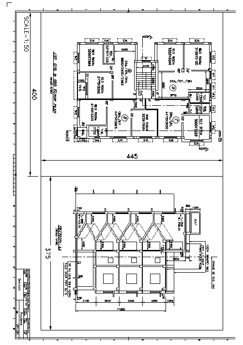
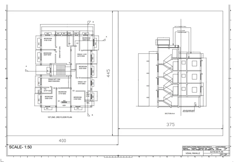
1. Create a layout of the Plan and Section A of the project in Challenges 7, using the template Tutorial-mArch.dwt in a scale as given in the Figure. Use the MV command to create the viewport of the size as shown in Figure. Also, use ATTEDIT command to edit the information in the title block. Use A1 size for the layout. Take a plot.
AIM:
To Create a layout of the plan and section A of the project in challenges 7 .
COMMANDS USED
- Limmax
- Limits
- Xref
- Layout
- ATTEDIT
- Multiple viewports
- Model Space
- Paper Space
- dtext
- DIMLINEAR
PROCEDURE:-
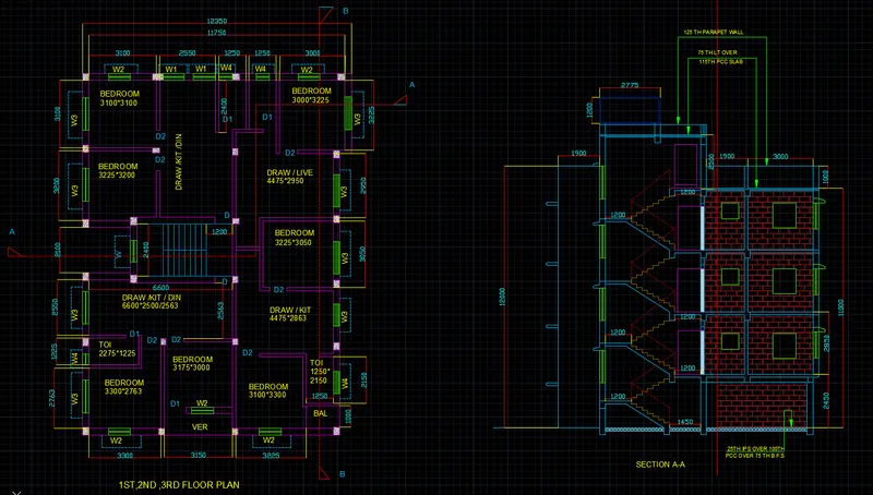
- Open existing plan from week 7 challenges , which is as below;
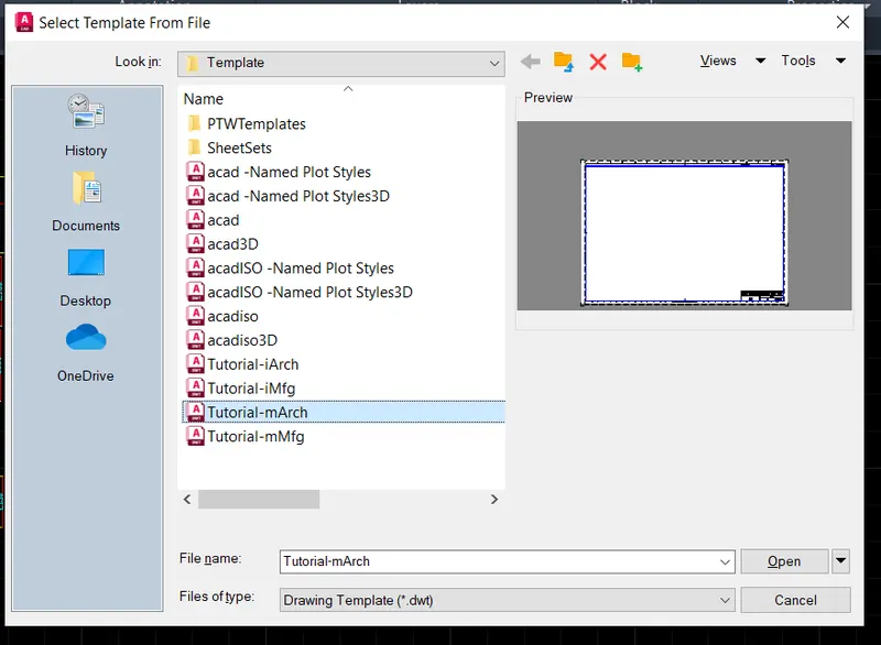
- Select the Template file to load into the drawing
- Select the template file as Tutorial-mArch.dwt
- Then click open to load the template into the layout
- the template mArch is as below;
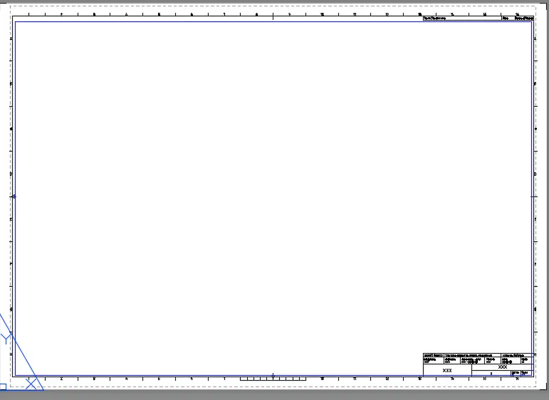
- check all the information obout the specific layout plotin page setup manager
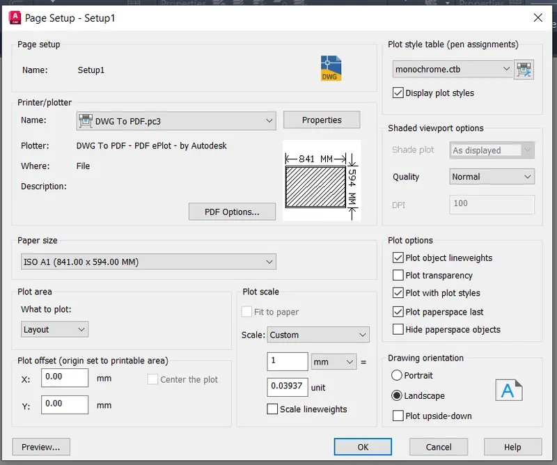
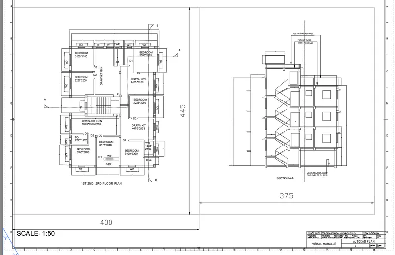
- for set up the view MVIEW<NEW<SELECT VIEW<PLOT IT TO LAYOUT SHEET
- with floor plan 400 mm from left and section plan with 375 from floor plan
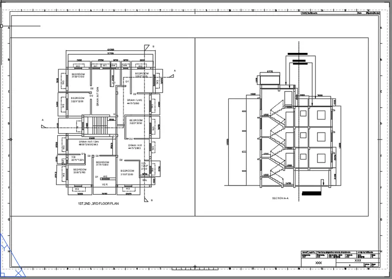
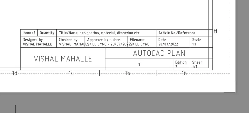
- After Loading the Layout template into the drawing, now we have to change the attributes
- type ATTEDIT in the command box to open the Edit Attributes dialog box
- Rename the title blocks as shown in the figure below
- After completing changes in the Edit Attributes, click on ok to make changes
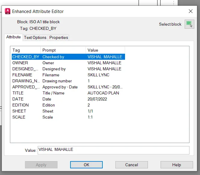
- The atributes changes are as below;
- give the dimensions to the viewport and mentioned the scale at the left
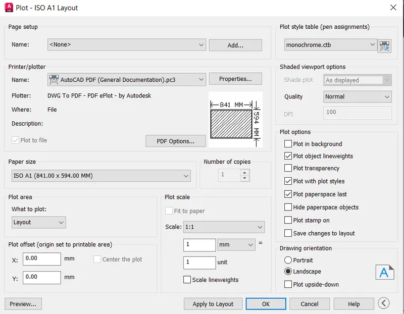
- Now Type Plot in the command box to open the Plot and a print dialog box
- Select the Plot type as DWFx plot.pc3 and paper size as ISO A1
- Select the Plot area as Extents and Scale as 1:1 as per the given requirement
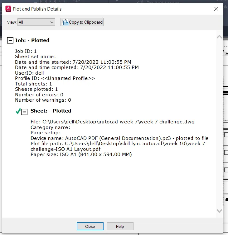
- Plot and publish details are as below;
FINAL RESULT:-
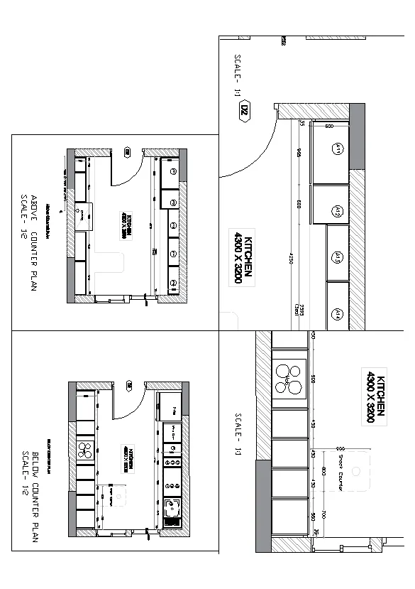
2. Create a layout of the Kitchen drawn in Challenge 9 as shown in Figure. Use the scale as shown in the Figure. Use A4 Size page for the layout. Take a plot.
AIM:
To Create the Layout of the Kitchen drawn in challenge 9 using the appropriate scale and A4 size page
INTRODUCTION:
A layout template is a layout imported from a DWG or DWT file. The program has sample layout templates to use when we design a new layout environment.
COMMANDS USED:
1. Viewports
2. Multiple views (MVIEW)
3. Model Space (MS)
4. Paper Space (PS)
5. Pan
6. Print
PROCEDURE:
- Open the Autocad Application from the desktop
- On the Autocad homepage, Click on Open drawing
- Open the Kitchen layout drawing that we created in the challenge 9
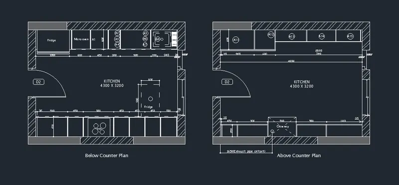
- Now we have to create the various views of the kitchen layout from the view tab
- Go to the view tab and select the option called New View
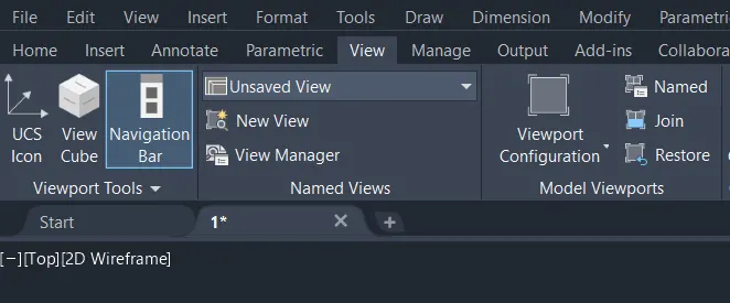
- After clicking on the New View option, a New view dialog box will appear
- Create the view name Below the counter plan and Boundary as the Current display
- After making changes, click on ok and then close the dialog box
- Similarly Create the other views of the kitchen layout using the view tab
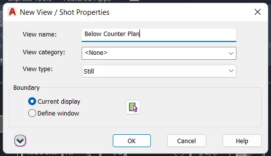
- Type Layout in the command box to open the new Layout
- Type New in the command box and rename it as Kitchen counter-plan
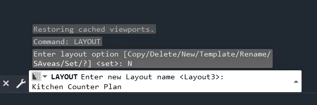
- After making changes, a new layout will appear on the screen
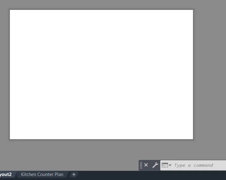
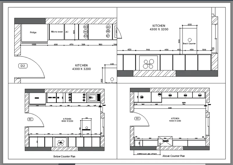
- Open the Viewports dialog box by typing MV in the command box
- Select the Viewports type as Four: Equal as shown in the figure below
- Adjust the Viewports spacing according to the requirement.
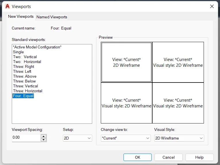
- After Creating the multiple viewports, now we have to adjust the zooming and scaling
- Type MS in the command box to switch the mode into Model Space
- Adjust the visibility of the plan and section using the Pan tool
- Adjust the scaling to 1:1 and 1:2 as per the given requirement.
- Now Type Plot in the command box to open the Plot and a print dialog box
- Select the Plot type as DWG to PDF.pc3 and paper size as ISO A1
- Select the Plot area as Extents and Scale as 1:1 and 1:2 as per the given requirement
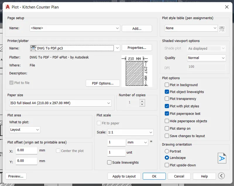
- Then Click on Preview to see the preview of the Layout
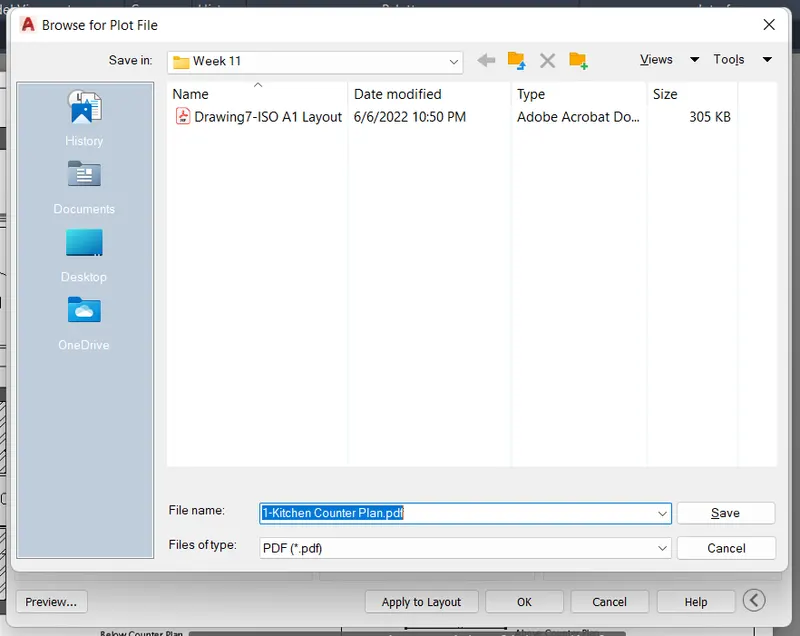
- After Settlings have been made, click on Ok to print or save it to the local folder
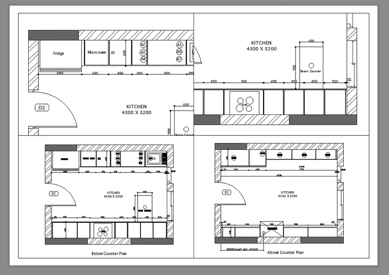
RESULT:
The different viewports of the drawing is as below;
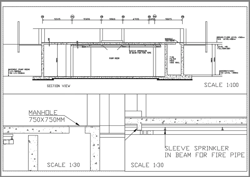
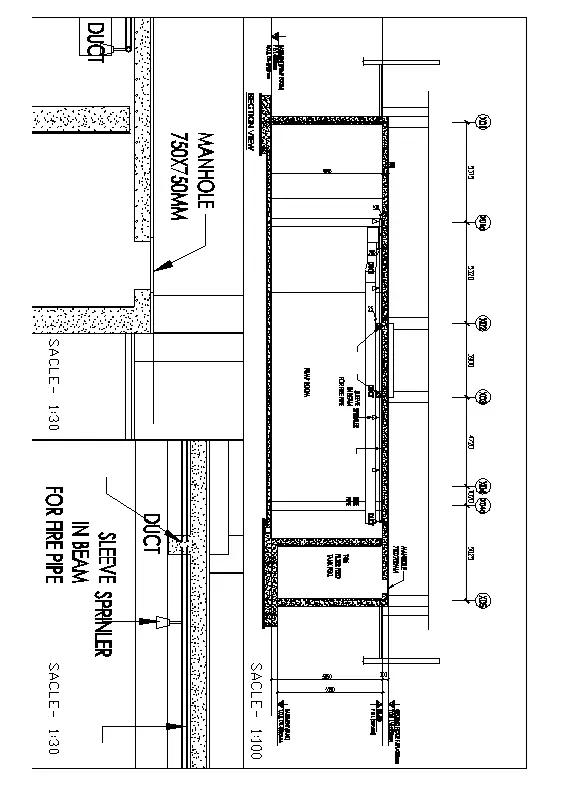
3. Create a layout of the section created in Challenges 9.
Use scale as mentioned in the Figure. Use MV command create multiple viewports. Take a plot.
AIM:
To Create layout of the section created in challenges 9
PROCEDURE:
- Open the file in which challenge 9 is created
- Give command layout to involk the layout tool to make a new layout .
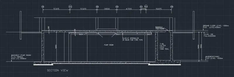
- Select the MV command to create the new view
- Then from the model screen, the view manager tab will display then select the view option
- After selecting the new option in the view manager as shown in the figure, and select the boundary on that tab as current display
- Next create the 1st view using the MV command, that we take the scale as 1:100
- Again, select the MV command and select the new option and create the 2nd view as required views
- Create the 2nd view using the MV command, that take the scale as 1:30
- Now create the 3rd view using the MV command, that we take the scale as 1:30
- Finally convert the DWG to pdf file using the plot command as shown in the above figure.
- Next select the A1 paper size for fit the drawing in the paper as shown in the below figure
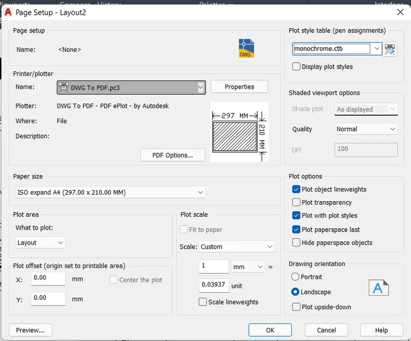
- Next select the pen assignments as monochrome.ctb.. Then select the apply to layout and click the ok option.
- Then finally the dwg file is exported to the pdf file as shown in the below figure.
- Then click on plot dialog box to plot a views and make a sheet out of it
RESULT:-
The various views from the given plan are as below: