Modelling and Assembly of Yacht -SolidWorks
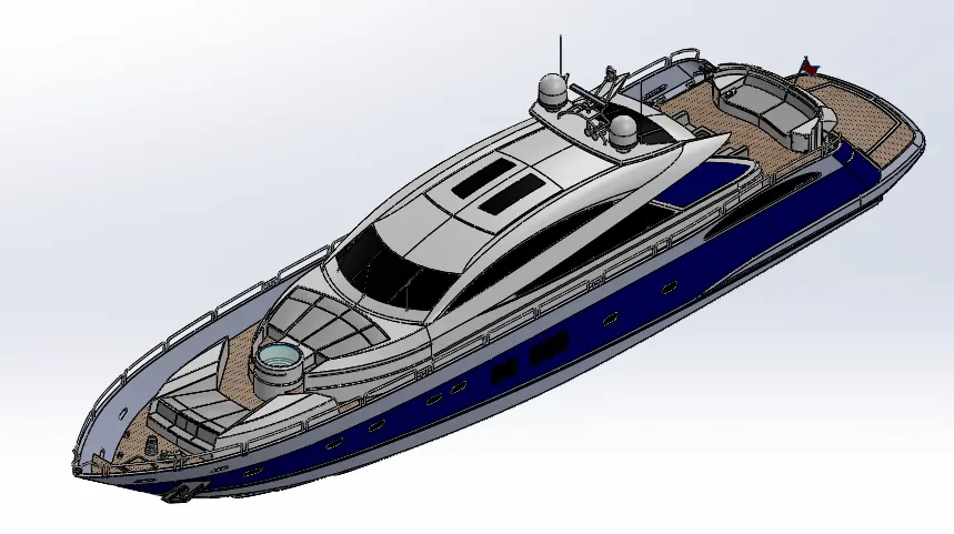
Objective: To Deisgn the parts in Solidworks and make an assembly using the modeled parts. Finally create photo realistic renders of the yacht using photoview 360 or Solidworks Visualize.
Introduction: yacht is a type of vessel which is used for crusing or racing. It usually has a cabin so there is place to stay overnight. In early days yachts are sailing boats, but now a days there are motorised.
racing yachtss prioritise speed over comfort but for normal yachts comfort is not compromised.
This yacht is modelled using advanced surface modelling tools of SolidWorks.Finally, all the parts are assembled. Photorealistic renders are created using visualize with the final assembly.
Parts to be Modelled:
Following Parts are modelled and assembled in SolidWorks.
- Propeller
- Radar
- Hull
- Garage Door
- Front Seat
- Middle Seat
- Rear Seat
- Super Structure
- Radar Mast
Tools/Features used:
Sketch Features:
- Line: Used to create straight line and tangent arcs to the line sketched previously.
- Clicle: Used to sketch circle of required dimensions.
- Rectangle: Different types of rectangle can be sketched like corner rectangle, 3 point
rectangle,center retangle etc - Arc: Different types of arcs like 3 point arc, tangent arc, center point arc can be
sketched. - Spline: Used to create spline lines and can be adjusted by modifying the handles as
per requirements. - Convert Entities: Used to bring the pervious sketch entities or edges of a solid profile
to persent sketch plane - Offset Entities: This feature allows us to offset a part of sketch or a entire sketch with
a certain distance - Mirror Entities: Used to mirror centain sketch entities along a certain reference line.
- Trim Entities: Used to trim unnecessary sketch entities depending on requirement.
- Pattern: Used to pattern sketch entites based on selection like linear patter or circular
pattern etc. - Text: Creates text on a continuous curve.
Solid Features:
- Extrude Boss/Base: Entrudes a sketch or sketch contours based on selection in one
direction or two direction to create a solid body based on the requirement. - Revolve Boss/Base: Revolves a sketch or sketch contours based on selection around a
axis along with angle which can be specified to create a solid body - Lofted Boss/Base: Adds material between two or more profiles. created solid bodies.
- Swept Boss/Base: Sweeps a profile (open or closed) to create a solid body.
- Extrude Cut: Cuts a solid body bt extruding a profile in one or two directions, can be
used to cut multiple bodies as well. - Fillet: Creates a rounded profile which can be internal or external depending on
selection on a solid or suface body. - Chamfer: This tools creates a bevelled feature on the selected edge or face of the
body. - Pattern: Patterns features, faces or bodies based on selection of feature like linear or
circular or sketch driven etc - Shell: Hollows out the part leaving a thin wall and opening the faces that are selected,
if no faces are selected then it creates a closed, hollow model. - Mirror: Mirrors features, faces and bodies about a plane face or a plane itself.
- Refernce Planes: Used to create reference planes or axis based on the contrains
- Projected Curve: Used to create a 3d curve based on two 2d skethes
- Split Line: Uses a sketch open or closed to split any face based on selection.
- Split Bodies: Split a single body into multiple bodies
- Spiral or Helix: Used to create a spiral or helix based on the sketch.
- Dome: Creates a dome (circular or elliptical) on a selected face or faces.
Surface Featuresu:
- Extrude Surface: Extrudes a selected countours in one or two directions to create a surface.
- Swept Surface: Sweeps a closed profile along a open or closed profile, can be defined
by constrains or guide curves. - Lofted Surface: Creates a loft surface between multiple profiles or sketches cnd
constrains can be defined. - Trim Surface: Trims where a surface intersects with another surface, Trim tool can be
- Ruled Surface: inserts rulled surface in a specified direction from edges.
selected and the surface to remove or keep can also be defined. - Filled: Patches a surface with in a boundary defined by edges.
- Extend Surface: Extend the selected surface base of conditions provided.
- Knit Surface: Combines multiple adjacent nonintersecting surface into a single
surface and also can made into a solid if it is a closed volume.
Appearances:
- Apperance option are used based on a face or body selections.
- Some parts also have additional decals.
Part Modelling:
Propeller:
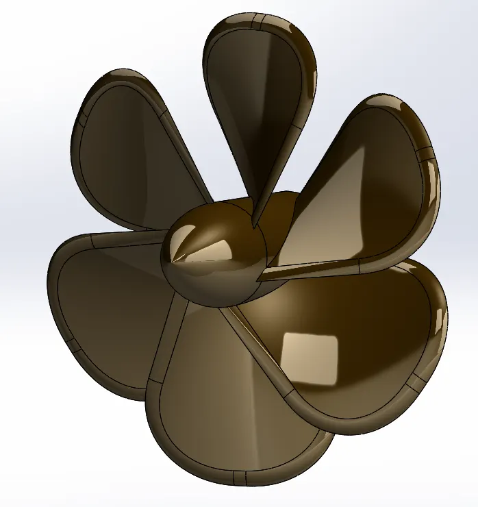
Propeller is used to convert rotational energy into thrust by propelling the fluid medium in which they are used. They are usually mounted at the rear bottom of the Yacht
Feature/Tools used:
Sketch
Revolve Boss/Base
Extrude Cut
Lofted Boss/Base
Fillet
Circular Pattern
Appearences
Radar:
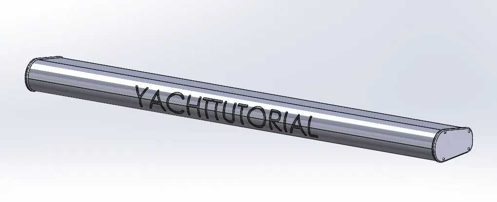
Radars are used to detect other ships. These are mounted on top of the yacht
Features/Tools used:
Sketch
Extrude Boss/Base
Mirror
Extrude Cut
Fillet
Sketch Driven Pattern
Split Line
Hull:
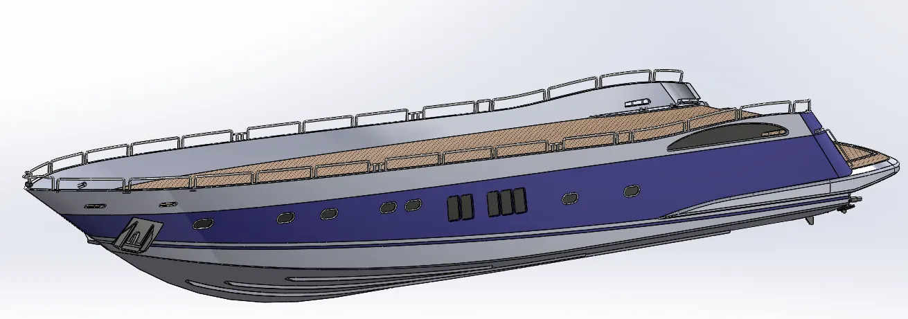
Hull is the structural entity of the ships and is a the water tight enclouser of ship.
Modelling of hull is done with the help of the blueprints.
Features/Tools used:
Sketch
Projected Curve
Swept Surface
Surface Loft
Shell
Surface Extrude
Revolve Boss/Base
Knit Surface
Extrude
Mirror
Extrude Cut
Fillet
Chamfer
Pattern
Split
Offset Surface
Split Line
Appearence
Garage Door:
Garage Door is used to close the garage. mounted at the garge space
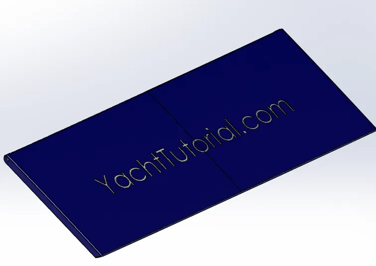
Feature/Tools used:
Insert part
Shell
Fillet
Extruded Cut
Text
Mirror
Appearence
Front Seat:
Front Seat is mounted at the front end of the yacht
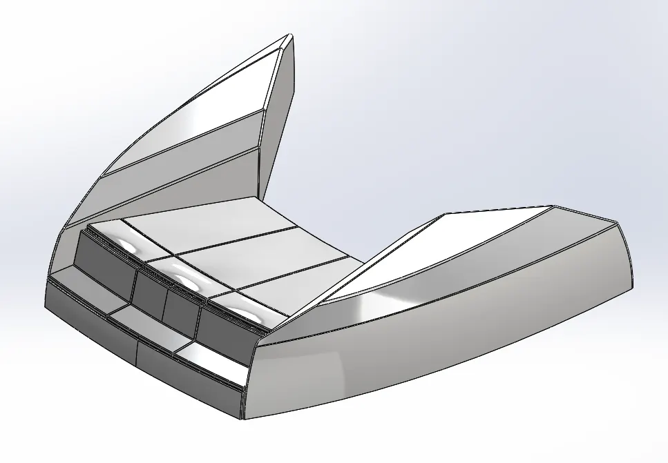
Features/Tools used:
Sketch
Projected Curve
Swept Surface
Trim Surface
Knit Surface
Revolve Boss/Base
Extruded Cut
Chamfer
Fillet
Mirror
Dome
Appearence
Middle Seat:
The Middle seat is mounted behind superstructure and Rear seat
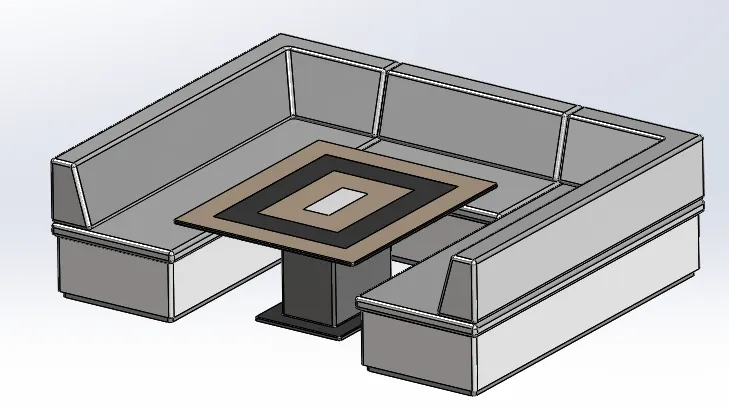
Features/Tools Used:
Insert Part
Extruded Boss/Base
Chamfer
Mirror
Fillet
Extruded Cut
Appearence
Rear Seat:
This is mounted on the rear of the deck surface.
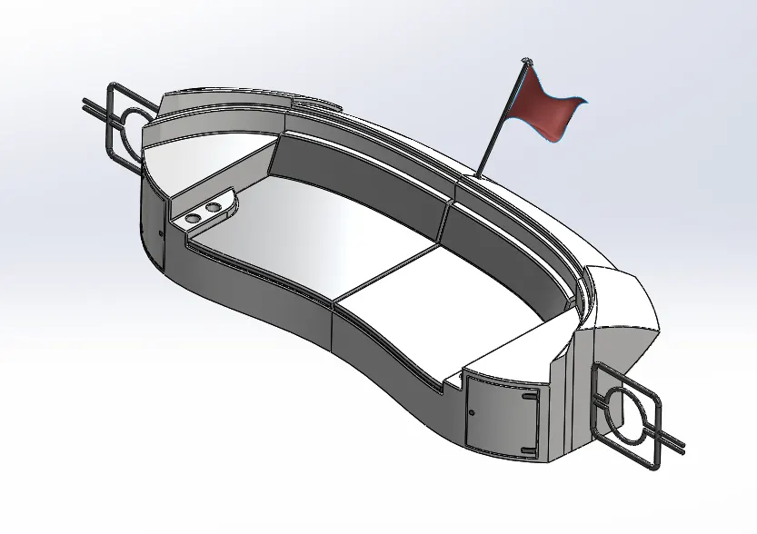
Features/Tools used:
Insert Part
Swept Surface
Surface Offset
Trim Surface
Knit Surface
Extend Surface
Ruled Surface
Lofted Surface
Extruded Boss/Base
Extruded Cut
Offset Surface
Fillet
Swept Boss/Base
Mirror
Revolve Boss/Base
Chamfer
Boundary Surface
Appearence
Super Structure:
This is built above hull and main deck. It aides with the structural strength of the ship.
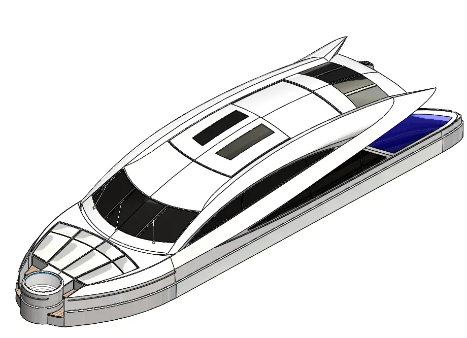
Features/Tools used:
Insert Part
Extruded Surface
Swept Surface
Knit Surface
Fillet
Ruled Surface
Lofted Surface
Filled Surface
Trim Surface
Knit Surface
Extend Surface
Extruded Boss/Base
Extruded Cut
Thicken
Offset Surface
Dome
Chamfer
Split Line
Mirror
Swept Boss/Base
Appearence
Radar Mast:
It is mounted above the Super Structure and supports the radar.
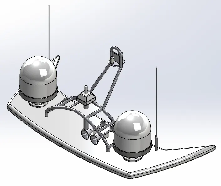
Features/Tools used:
Inser Part
Extruded Boss/Base
Fillet
Revolve Boss/Base
Swept Boss/Base
Mirror
Mirror
Chamfer
Shell
Appearence
Assembly of Yacht:
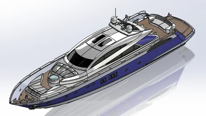
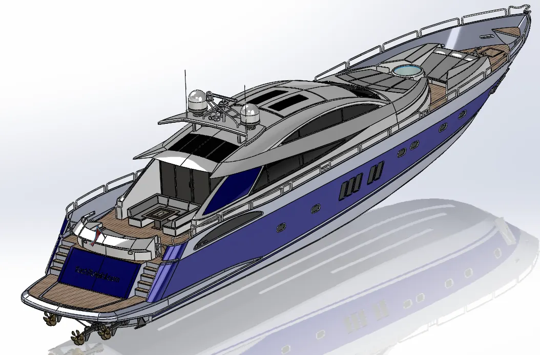
Initially the hull of the yacht is imported and fixed in the assembly workspace,then all the other parts are imported and fixed with respect to hull.
Renders:
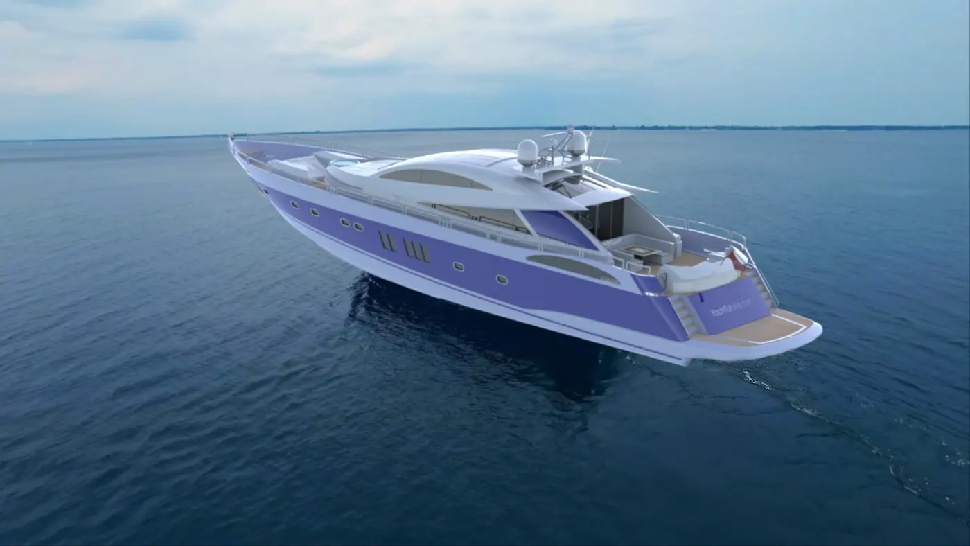
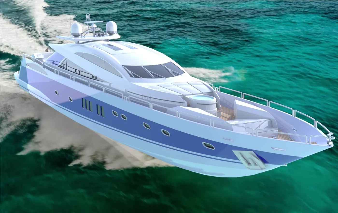
The renders are made in SolidWorks Visualize using backplate environment.
Conclusion:
- All the parts are modelled in solidworks.
- Using Solidworks Assembly tools all the parts are assembled
- The assembly is imported into SolidWorks Visualize and photorealistic render are made.