Modelling of American Chopper - SolidWorks
Design and Modelling of American Chopper:
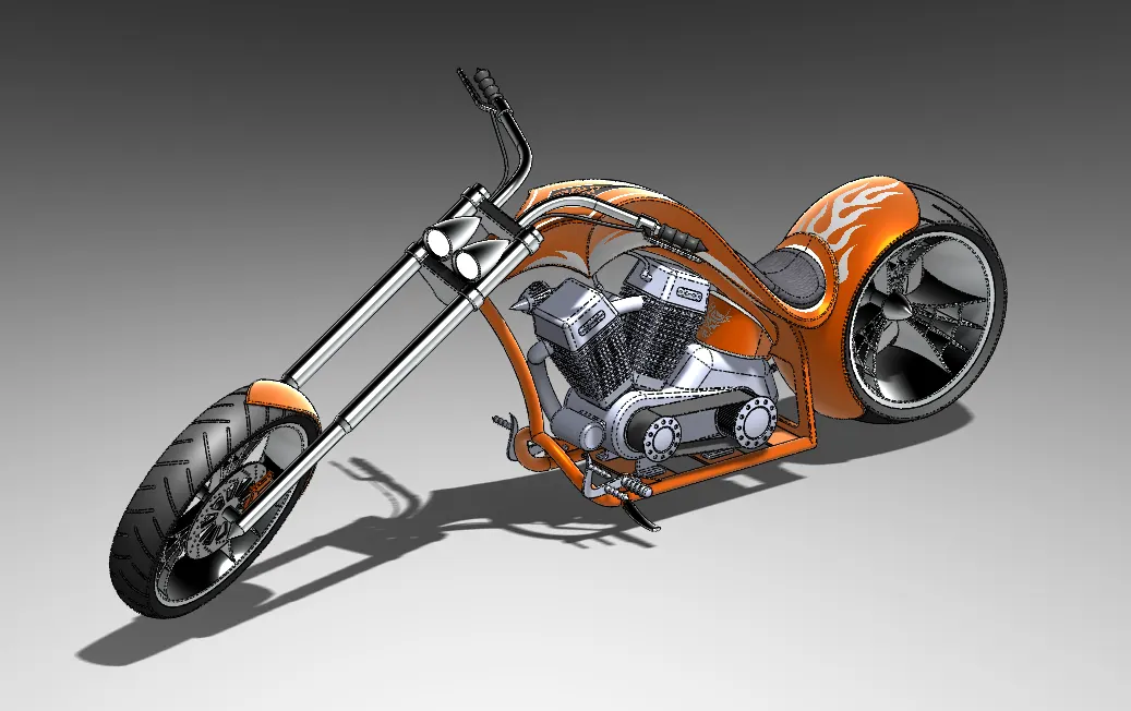
Objective:
- To uderstand the interface and various modelling tools in solidworks
- Using solid modelling and surface modelling tools to model the chopper
Using solidworks assembly tools to combine all the parts which are modelled individually as solidworks part
- Using photoview 360 (Solidworks Add-in) and Solidworks visualize to create photo realistic renders
Introduction:
- All the parts of the chopper are modelled using Solidworks solid modelling tools except for fuel tank which is modelled using surface modelling tools.
- After all the parts are modelled, All of them are imported to Solidworks Assembly workspace. Using the mates and advanced mates in Solidworks Assembly tools, Final Assembly of the chopper is done.
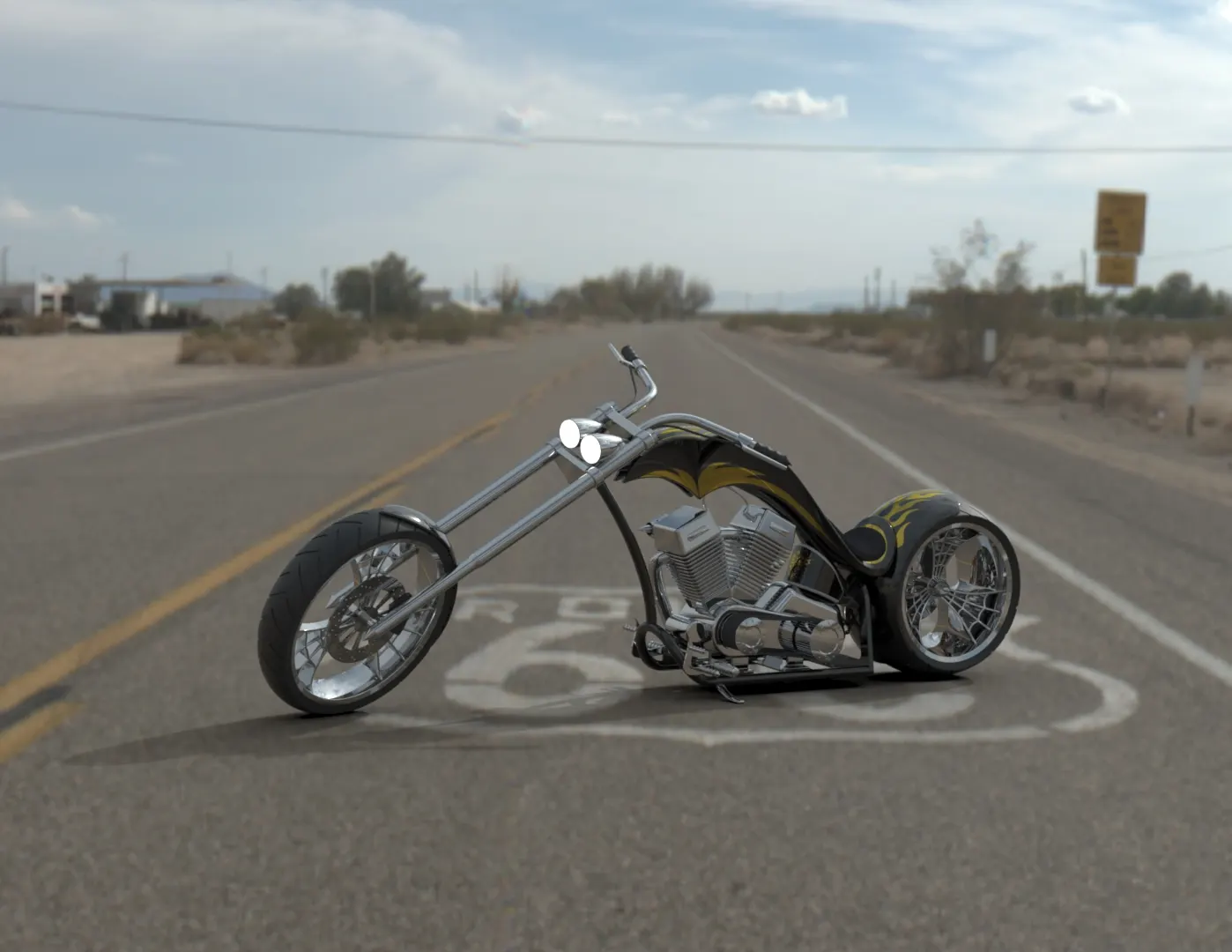
- As the assembly is done. Using Solidworks Add-in which is Photoview 360 and Solidworks Visualize photo realistic renders are obtained.
Parts to be modelled:
- Transmission Belt
- Kickstand
- Front Fender
- Rear Fender
- Oil Tank
- Chain
- Pedal
- Front Wheel
- Rear Wheel
- Front Fork
- Chassis
- Engine
- Gas Tank
Features Used:
Sketch Features:
- Line: Used to create straight line and tangent arcs to the line sketched previously.
- Clicle: Used to sketch circle of required dimensions.
- Rectangle: Different types of rectangle can be sketched like corner rectangle, 3 point rectangle,center retangle etc.
- Arc: Different types of arcs like 3 point arc, tangent arc, center point arc can be sketched.
- Spline: Used to create spline lines and can be adjusted by modifying the handles as per requirements.
- Polygon: Used to sketch the ploygon of desired number of sides.
- Convert Entities: Used to bring the pervious sketch entities or edges of a solid profile to persent sketch plane.
- Offset Entities: This feature allows us to offset a part of sketch or a entire sketch with a certain distance.
- Mirror Entities: Used to mirror centain sketch entities along a certain reference line.
- Dynamic Mirror: Mirror sketches entities as the sketching is done.
- Trim Entities: Used to trim unnecessary sketch entities depending on requirement.
- Pattern: Used to pattern sketch entites based on selection like linear patter or circular pattern etc.
- Blocks: These help to use a single sketch multiple times and places. for example, if there is a sketch of nut which is used many times in model, then we can use blocks rather than sketching the entire profile again.
Solid Features:
- Extrude Boss/Base: Entrudes a sketch or sketch contours based on selection in one direction or two direction to create a solid body based on the requirement.
- Revolve Boss/Base: Revolves a sketch or sketch contours based on selection around a axis along with angle which can be specified to create a solid body .
- Swept Boss/Base: Sweeps a profile (open or closed) to create a solid body.
- Swept Cut: Cuts a body by sweeping a open or closed profile along an axis.
- Extrude Cut: Cuts a solid body bt extruding a profile in one or two directions, can be used to cut multiple bodies as well.
- Fillet: Creates a rounded profile which can be internal or external depending on selection on a solid or suface body.
- Chamfer: This tools creates a bevelled feature on the selected edge or face of the body.
- Pattern: Patterns features, faces or bodies based on selection of feature like linear or circular or sketch driven etc
- Shell: Hollows out the part leaving a thin wall and opening the faces that are selected, if no faces are selected then it creates a closed, hollow model.
- Mirror: Mirrors features, faces and bodies about a plane face or a plane itself.
- Combine Bodies: Combines two or more solid bodies to create a single body.
- Split Bodies: Split a single body into multiple bodies.
- Move/Copy bodies: This tools hels us to move or copy a body or bodies.
- Refernce Planes: Used to create reference planes or axis based on the contrains.
- Projected Curve: Used to create a 3d curve based on two 2d skethes.
- Composite Curve: Used to combine multiple projected curves to one curve.
- Split Line: Uses a sketch open or closed to split any face based on selection.
- Dome: Creates a dome (circular or elliptical) on a selected face or faces.
Surface Features:
- Swept Surface: Sweeps a closed profile along a open or closed profile, can be defined by constrains or guide curves.
- Lofted Surface: Creates a loft surface between multiple profiles or sketches cnd constrains can be defined.
- Boundary Surface: Creates a surface between profiles that can be tangent or curvature continuous in all directions.
- Trim Surface: Trims where a surface intersects with another surface, Trim tool can be selected and the surface to remove or keep can also be defined.
- Knit Surface: Combines multiple adjacent nonintersecting surface into a single surface and also can made into a solid if it is a closed volume.
Appearances:
- Apperance option are used based on a face or body selections.
- Some parts also have additional decals.
Part Modelling:
- Transmission Belt
Transmission belt is used to transmit the power from enigine crank to gear box
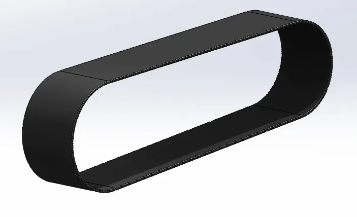
Features/Tools used for Transmission Belt
Sketch
Offset
Extrude Boss/Base
Fillet
Appearences
- Kickstand
This components is used to support the chopper when it is parked
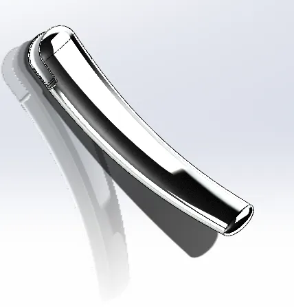
Features/Tools used for Kick Stand
Sketch
Loft
Dome
Extrude Boss/Base
Extrude Cut
Fillet
Split
Apperances
- Front Fender
Front Fender is used to protect the rider and chopper itself from debris on road. This is mounted above the front wheel and between the arms of the front fork
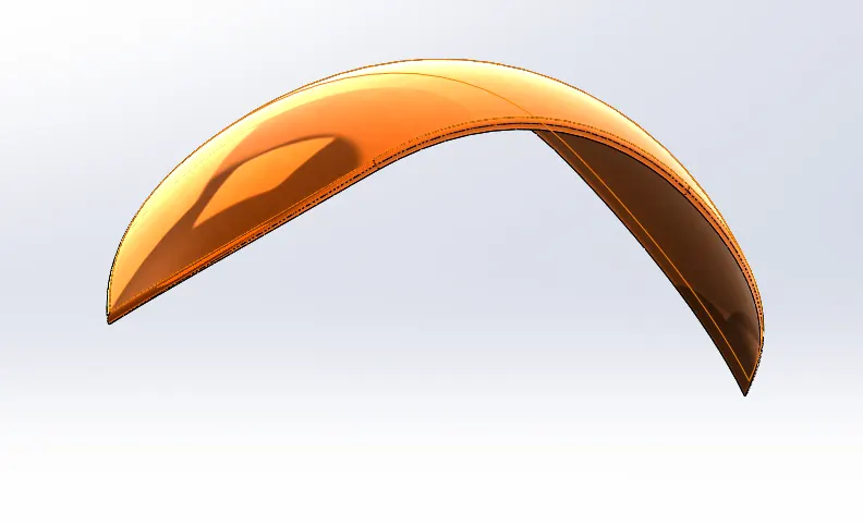
Features/Tools used for Front Fender
Sketch
Offset
Trim Entities
Revolve Boss/Base
Dynamic Mirror
Split
Appearences
- Rear Fender
The fuction of rear fender is same as the front fender and is monted on the rear of the chassis and between the support arms for rear wheel
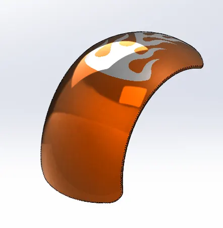
Features/Tools used for Rear Fender
Sketch
Offset Entities
Trim Entities
Revolve Boss/Base
Appearences
- Oil Tank
Oil tank is used to store the oils like engine oil. This is a hollow part of 3mm thickness. Thisis mounted above the gear box and infront of rear fender
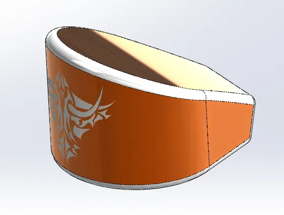
Features/Tools Used for Oil Tank
Sketch
Extrude Boss/Base
Combine
Fillet
Shell
Appearences
- Chain
Chain is another mode of transmission system like transmission belt, which is used to transmit the power from output of gear box to rear wheel which the help of sprokets
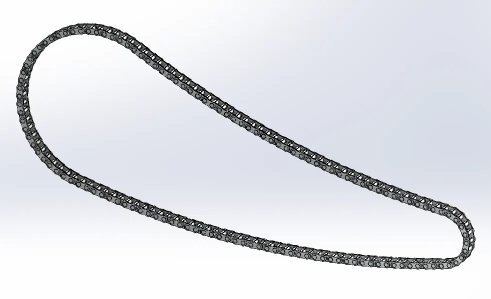
Features/Tools used for Chain
Sketch
Trim
Fillet
Blocks (Here Blocks of links are created and used along the path)
Extrude Boss/Base
Pattern
Appearences
- Pedal
Pedals are used to rest the legs of the rider. it is mounted on either side of the chassis.
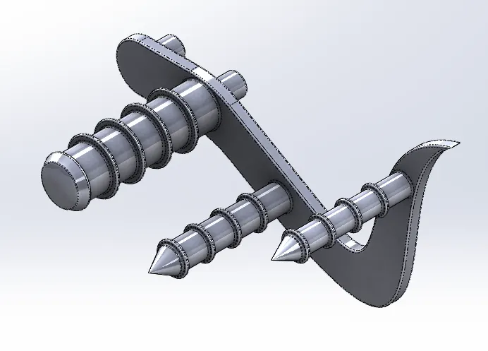
Features/Tools used for pedal
Sketch
Extrude Boss/Base
Fillet
Linear Pattern
Dome
Chamfer
Appearences
- Front Wheel
Front Wheel consists of a Tire and Rim which are used give motion to the chopper by rolling. Front Rotor and Caliper are mounted. This is mounted on the Front axle
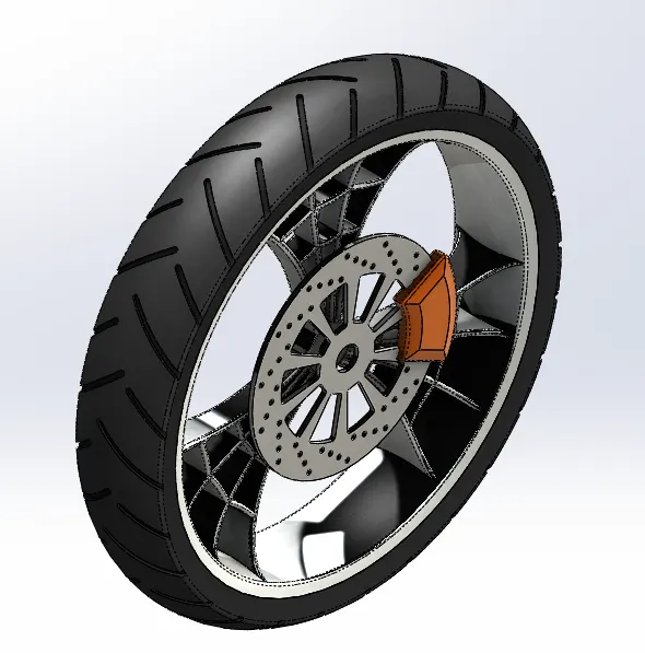
Feartures/Tools used for Front Wheel
Sketch
Revolve Boss/Base
Trim
Fillet
Extrude Boss/Base
Revolve Cut
Linear Pattern
Chamfer
Circular Pattern
Appearences
- Rear Wheel
Rear Wheel consists of Rear Tire and Rim which roll as the chopper moves. Rear Rotor, Caliper and Sprocket are mounted. This gets the power from the gear box through sprocket, This is the driving wheel for the chopper
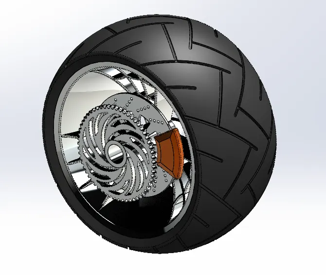
Features/Tools used for Rear Wheel:
Sketch
Revolve Boss/Base
Trim
Fillet Entities
Planes
Revolve Cut
Linear Pattern
Chamfer
Fillets
Extrude Cut
Circular Pattern
Appearences
- Front Fork
Front Fork consists of the front suspension assembly, front axle, head lights, handels, brake lever. This is mounted at the front of the chassis. It is used for turning the chopper, also absorbs front shocks as shock absorbers a part of front fork.
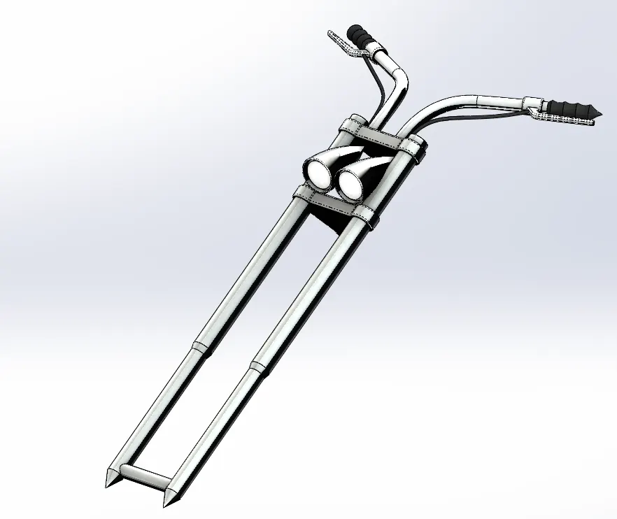
Features/Tools used for Front Fork
Sketch
Extrude Boss/Base
Trim
Revolve Boss/Base
Split
Plane
Convert Entites
Move/Copy Bodies
Dome
Mirror
Combine Bodies
Curve
Swept Boss/Base
Appearances
- Chassis
Chassis is the main structural member for the motorcycle all of the components like Engine, Transmission, Supension Arms etc. This determines the strength of the chopper.
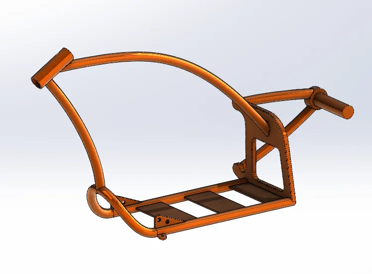
Feature/Tools used for Chassis
Sketch
Offset Entities
Convert Entities
Projected Curve
Trim
Plane
Swept Boss/Base
Split
Revolve Boss/Base
Extrude Cut
Fillet
Combine Bodies
Fillet
Combine
Appearences
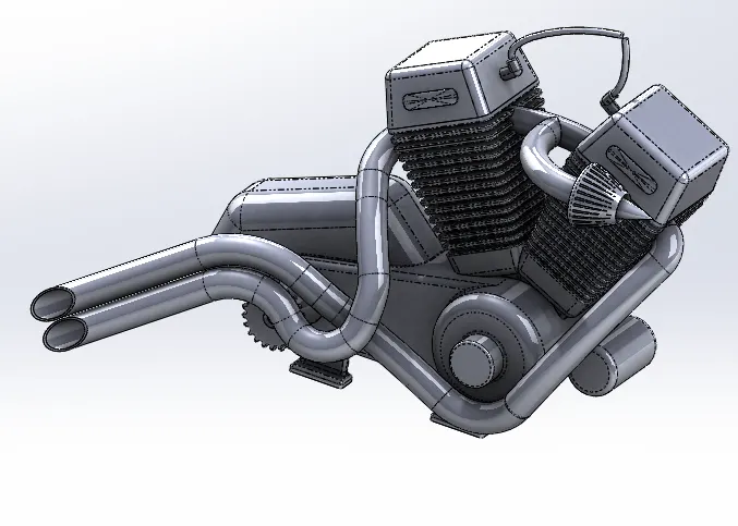
- Engine
Engine is the power source of the chopper. it provides power by converting thermal energy to mechanical energy. the piston which is present inside the cylinder moves linearly due to combustion of the fuel. This motion is converted to rotational motion with the help of crank chaft. This provides power to the gear box
Features/Tools used for Engine:
Sketch
Convert Entities
Trim
Revolve Boss/Base
Extrude Boss/Base
Extrude Cut
Offset Entities
Dome
Fillet
Projected Curve
Composite Curve
Sweep
Mirror
Circular Pattern
Split
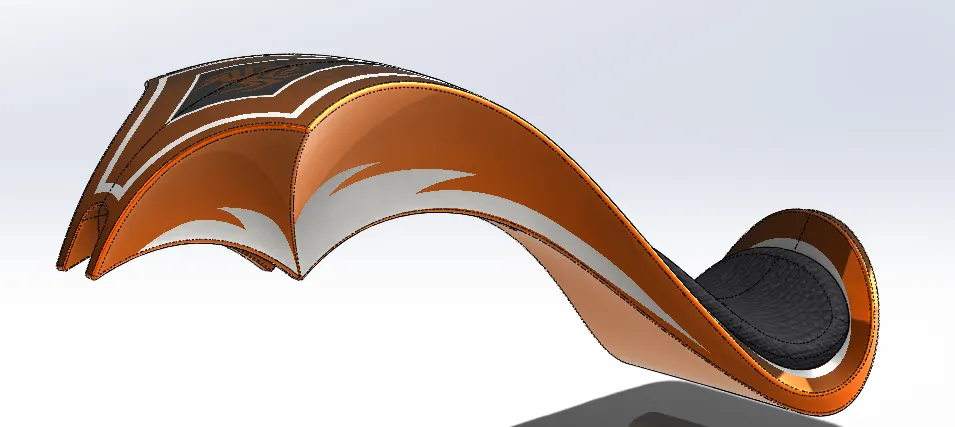
- Gas Tank
Gas Tank is used to store fuel which is used by the engine. It is mounted above the engine.
Features/Tools used for Gas Tank
Sketch
Trim
Projected Curve
Convert Entities
Swept Surface
Loft Surface
Fill Surface
Trim Surface
Knit Surface
Swept Cut
Fillet
Appearences
Assembly of the Chopper:
- Features/Tools used for assembly of chopper
Insert part
Mates
Advanced Mates
Mirror
- Some parts like Exhaust pipe and kick stand were adjusted to avoid intersecting geometry.
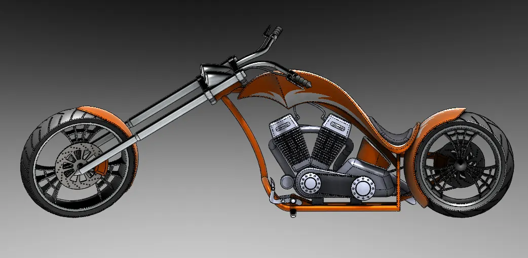
Side View:
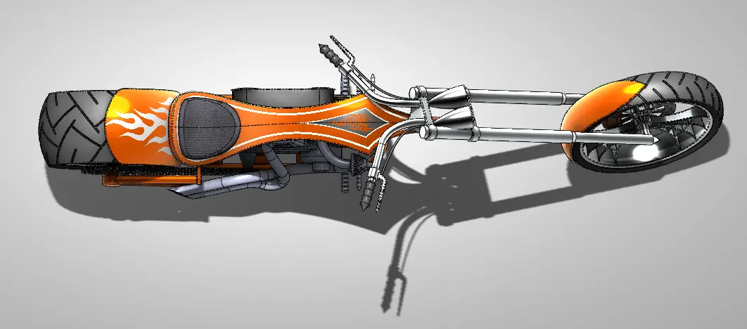
Top View:
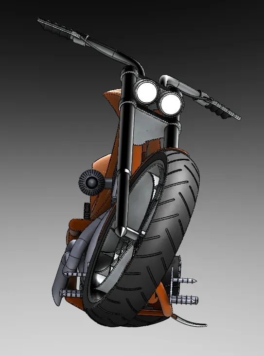
Front View: ISO View:
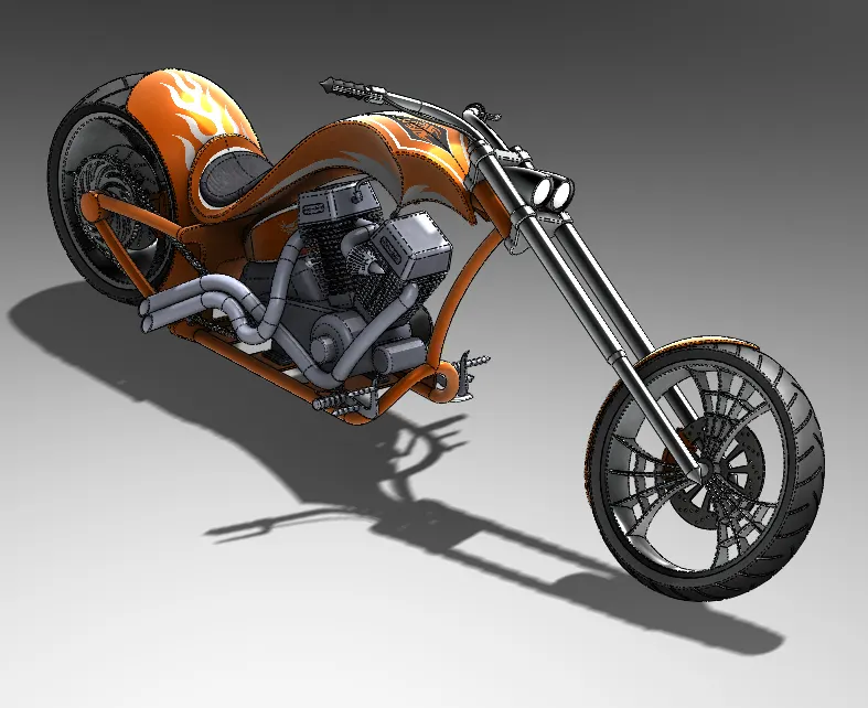
Cam View:
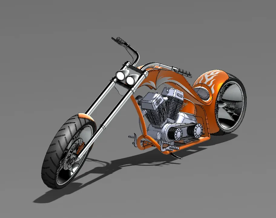
Rendering:
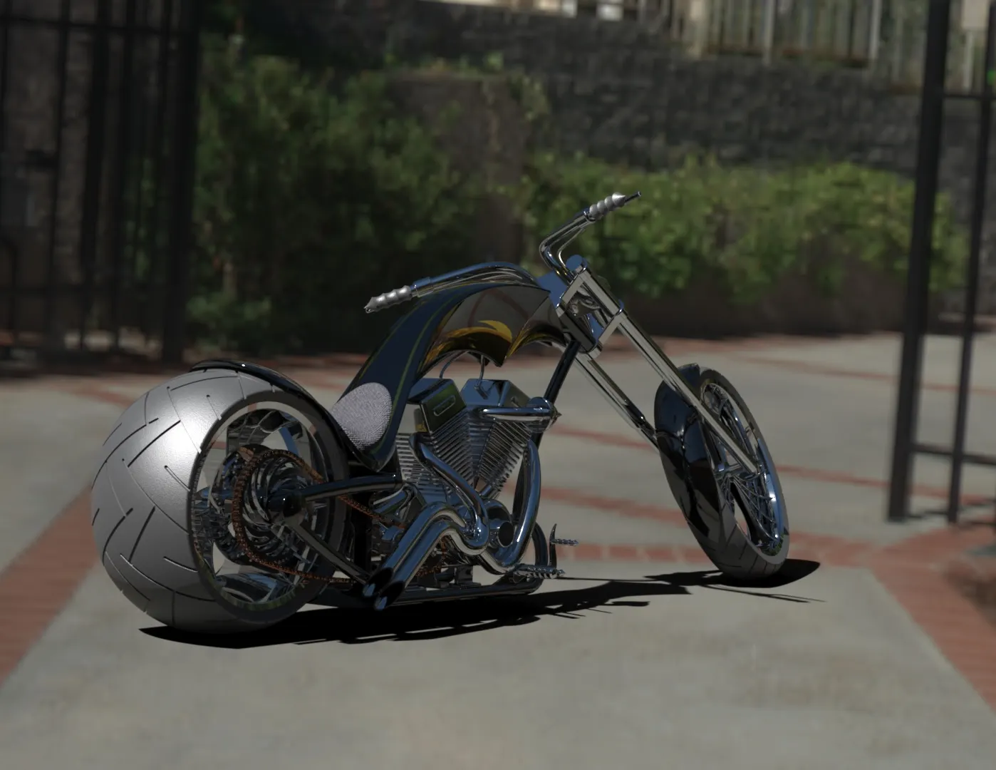
- Redering is a process carried out when entire modelling is completed along with assembly if required and it is ready for photorealistic image.
- SolidWorks has two tools that can be used for rendering Photoview 360 and SolidWorks Visualize. Photoview 360 is a Add-in for SolidWorks and Visualize is a separate application.
- In redering tools decals were applied to gas-tank, rear fender and oil tank.
- In redering tools, A enviroment can be added, different camera view can be added along with different lighting condition and light can be added
Photorealistic Render:
Conclusion:
- Using SolidWorks Tools for Solid modelling and Surface modelling the parts of the chopper had been modelled.
- SolidWorks Assembly Tools helped to combine all the parts and them in appropriate location.
- Finally, using solidworks visualize and photoview 360 photorealistic renders had been obtained.