EV Drivetrain
Objective:
- Which types of power converter circuits are employed in electric and hybrid electric vehicle?
- An Electric Vehicle's powertrain with 72V battery pack in shown in the diagram below. The duty ratio for acceleration operation is 'd1' and for the braking operation the duty ratio is 'd2'.
The other parameters of the electric vehicle is given below,
Motor and Controller Parameters:
Rated Armature voltage= 72 V
Rated armature current= 400 A
Ra= 0.5Ω, KΦ= 0.7 Volt second
Chopper Switching frequency= 400 Hz
The vehicle speed-torque characteristics are given by the equation
 What is EV steady state speed if duty cycle is 70%?
 -
Develop a mathematical model of a DC Motor for the below equation using Simulink.
`omega = V/{Kphi}-R_a/{Kphi^2}*T`
-
Refer to the blog on below topic: Induction Versus DC brushless motors by Wally Rippel, Tesla
Explain in brief about author’s perspective.
#1 Types of power converter circuits are employed in EV and HEV?
DC-DC Converter:
- A DC-DC converter is a power electronics device that accepts a DC input voltage and also provides a DC output voltage.
- The output voltage of DC to DC converter can be greater than the input voltage or vice versa. The converter output voltages are used to match the power supply required to the loads.
- The connection and disconnection of power supply to the load can be controlled using a switch in the simple DC to DC converter circuit.
- DC to DC converter circuits consists of a transistor or diode switch, energy storage devices like inductors or capacitors and these converters are generally used as linear voltage regulators or switched mode voltage regulators.
- DC to DC converters are used to provide DC regulated power supply, constant DC power supply to the electrical and electronics project circuits.
- The low input DC voltage is converted into high output DC voltage using DC to DC boost converter. As the input voltage is stepped up compared to output voltage, hence, it is also called as a step up converter.
- Generally, DC to DC converters can be designed using power semiconductor switching devices and discrete electrical and electronics components.
AC-AC Converter:
- AC to AC converters is used for converting the AC waveforms with one particular frequency and magnitude to AC waveform with another frequency at another magnitude.
- This conversion is mainly required in case of speed controlling of machines, for low frequency and variable voltage magnitude applications as well.
- We know that there are different types of loads that work with different types of power supply like single-phase, three-phase supply, and the supplies can be differentiated based on the voltage and frequency range also.
- We require a particular voltage and particular frequency for operating some special devices or machines. For speed control of induction motors, AC to AC converters (Cycloconverters) is used majorly.
- For obtaining a desired AC power supply from the actual power supply, we need some converters called AC to AC converters.
AC-DC Converter:
- The power electronics converter which is used for converting AC to DC is called as rectifier circuit. There are different types of power electronics converters such as rectifier.
- There are different circuits that can be used for converting the available 230V AC power to 5V DC power using various techniques.
- Generally, the step-down converters can be defined as converters with output voltage less than the input voltage.
- Working of AC - DC converter. Firstly, Stepping down the Voltage Levels. Then, AC to DC Power Converter Circuit will convert AC to pulsating. Obtaining Pure DC from Pulsating DC. Finally the DC voltage regulating DC voltage.
DC-AC Converter:
- DC to AC converters is mainly designed for changing a DC power supply to an AC power supply.
- Here, DC power supply is comparatively stable as well as positive voltage source whereas AC oscillates approximately a 0V base stage, typically in a sinusoidal or square or mode.
- A transformer coil system & a switch is the simple circuit used for an inverter. A typical transformer can be connected toward the DC signal’s input through a switch to oscillate back quickly.
- Due to the current flow in bi-directional in the primary coil of the transformer, an alternating current signal is an output throughout the secondary coils.
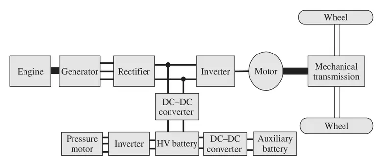
#2 An Electric Vehicle's powertrain with 72V battery pack in shown in the diagram below. The duty ratio for acceleration operation is 'd1' and for the braking operation the duty ratio is 'd2'.
The other parameters of the electric vehicle is given below,
Motor and Controller Parameters:
Rated Armature voltage= 72 V
Rated armature current= 400 A
Ra= 0.5Ω, KΦ= 0.7 Volt second
Chopper Switching frequency= 400 Hz
The vehicle speed-torque characteristics are given by the equation What is EV steady state speed if duty cycle is 70%?
We know that speed torque relation of the motor
`omega = V/{Kphi}-R_a/{Kphi^2}*T`
By rearranging
`T = V/{Kphi}*{Kphi^2}/R_a - {Kphi^2}/R_a*omega`
Where:
- V = Supply Voltage (Volts)
- `Kphi` = Motor Constant
- Ra = Armature Resisitance (ohm)
- `omega`= Angular Velocity (rad s-1)
- T = Torque (Nm)
Motor Voltage:
`Vm = Vb * d`
Where:
Vm = Voltage of motor
Vb = Voltage available at battery
d = Duty Cycle
therefore
Vm = 72*70%
Vm = 50.4V
From Torque Equation:
`T = 50.4/0.7*0.7^2/0.5-0.7^2/0.5*omega`
`T = 70.56-0.98*omega`--------------1
Given
`T_v = 24.7+0.0051*omega^2`------2
Equating 1 and 2
`70.56-0.98*omega = 24.7+0.0051*omega^2`
`omega^2 + 192.15 omega-8922.15 = 0`
Solution fot the above Eq
`omega = -192.15 +-sqrt{192.15^2-4*1*(-8922.15)}/{2*1}`
`omega = 38.6564 or -230.806`
as `omega` can't be -ve. So,
`omega = 38.6564 {rad}/sec`
`omega = 369.141 RPM`
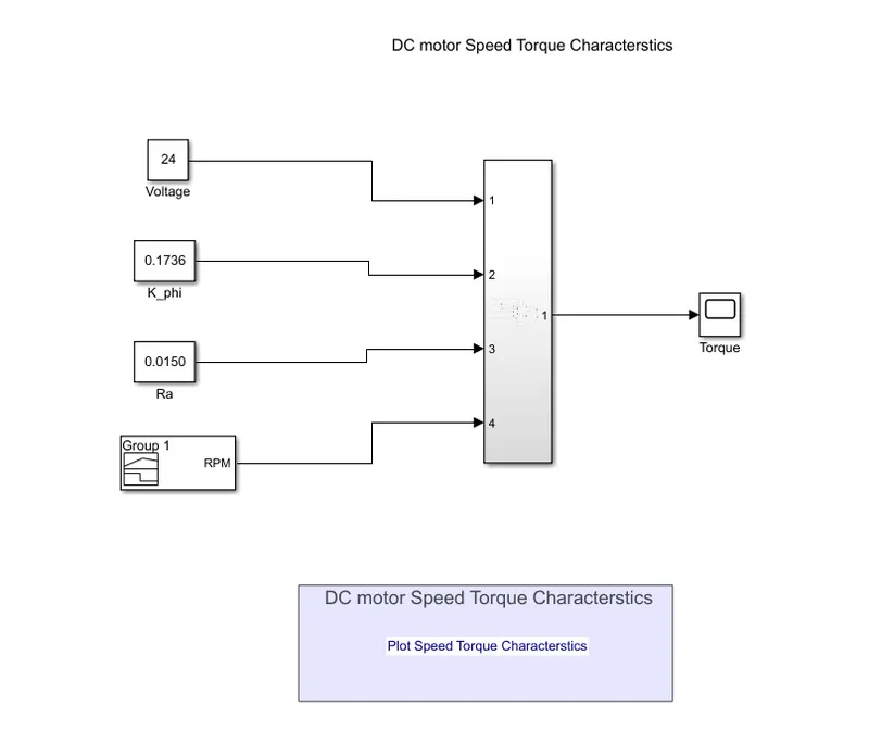
#3 Develop a mathematical model of a DC Motor for the below equation using Simulink.
`omega = V/{Kphi}-R_a/{Kphi^2}*T`
By rearranging the above equation:
`T = V/{Kphi}*{Kphi^2}/R_a - {Kphi^2}/R_a*omega`
Simulink Model: Click here
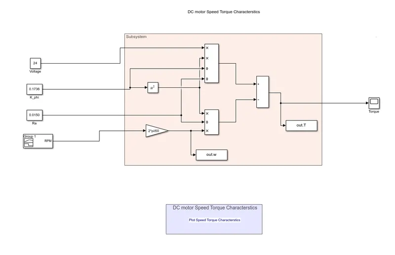
With Expanded subsystem:
Inputs:
Constant Block:
- Voltage
- Motor Constant
- Armature Resistance
Signal Builder:
- RPM
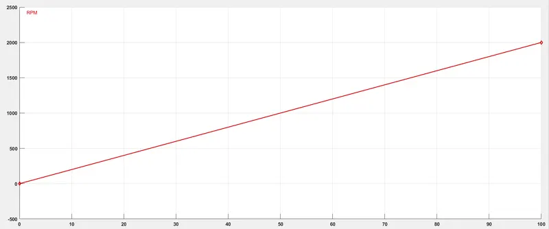
Working:
- The inputs are given as constants and rpm is given as signal builder. Then using gain block RPM is converted to rad s-1.
- The two terms of the equation are taken separately and using sum block in the end the term are subtracted.
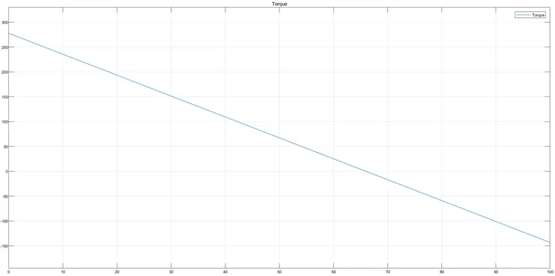
- The torque values are visualised using scope.
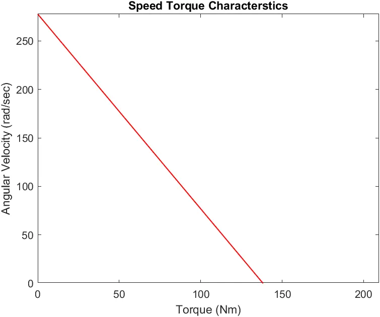
- The Angular velocity values are taken to workspace along with the torque values to plot speed vs torque plot
- Speed vs Torque plot is dne using an annotation
Output:
Scope:
- Torque Values
To work space:
- Angular velocity (rad s-1)
- Torque
Speed vs Torque Plot:
#4 Refer to the blog on below topic: Induction Versus DC brushless motors by Wally Rippel, Tesla Explain in brief about author’s perspective.
The author compares between DC Brushless motor and Induction motor used in EVs. He takes pros and cons of motor in terms of their performance. conrtrol, endurance, cooling system, torque and costs.
DC motors:
- The magnets used in this motor are permanent magnets. This can result in Magnetic losses if they are huge in size. Permanent magnets are expensive to manufacture.
- As these are permanent magnets their magnetic fiels cannot be varied.
- The stator construction is done by distributed windings inside stator core.
- These cannot generate starting torque from the onset when it is connect to a fixed frequency supply. Their speed can be controlled by using an inverter
- Inverter varies stator currents to generate rotating magnetic field and easier to control.
- These motor generate less heat and can be cooled easily.
- They are of high efficieny and can unity power factor.
AC motor:
- They don't use permanent magnets instead they use stacked stell laminations. They dont have any magnetic losses. As they dont have any magnet they are cheaper.
- As these are not permanent magnets their magnetic fiels can be varied.
- The stator construction is done by distributed windings inside stator core.
- These can generate starting torque from the onset when it is connect to a fixed frequency supply.
- No inverter necessary as they run directly from 3 phase current.
- These motor generate more heat due to eddy currents.
- They are of low efficieny and can 0.85 power factor.
He concludes that there is no winner among these motor. Hybrid electric vehicles prefer DC brushless motors and High performance EV prefer AC induction motor.