Simulink model for implementation of control logic of washing machine and gear shift
AIM:
- Implement control logic of a “washing machine”.
- Make a Simulink chart for the “Gear shift” logic.
#1: Implement control logic of a “washing machine”
- Theory:
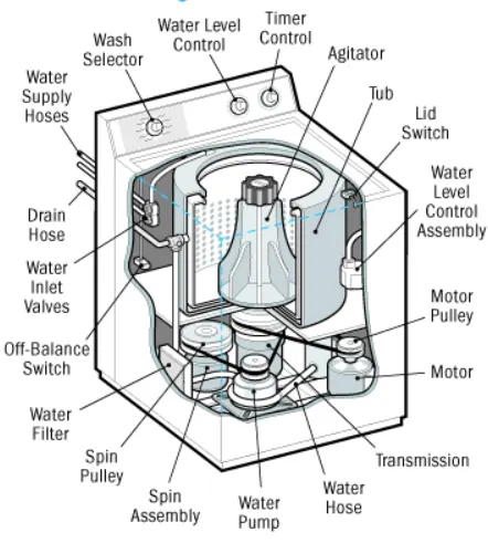
- Washing machine is the machine used to wash the various types of clothes without applying any physical efforts. The washing machine enables you to wash your clothes automatically without having to supervise its operation.
- The washing machine automatically takes in the amount of water and detergent required and it also automatically sets the timer for washing, rinsing and drying as per the selected mode and the amount of clothes.
- Types of washing machines: Front load, Top load; Semi automatic and fully automatic.
- Objective:
- If the power supply is available, the system gets activated
- If the Water supply is not available, stop the process & indicate through LED
- Soaking time should be 200s followed by Washing time of 100s.
- Then rinsing happens for next 20s & dryer runs for 50s
- After all the process are finished, turn on the 'process completed' LED.
- Simulink model:
- Chart Block (Logic):
- Procedure:
- Create a blank simulink model, create a chart block and define the state flow as per the given obejectives.
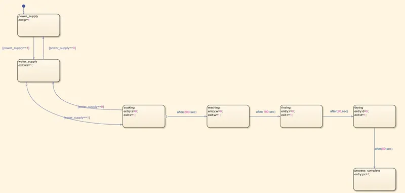
- The first state checks if the power supply is turned on or off. If the power supply is turned on then it proceeds to the next state.
- The following state checks the availability of water supply i.e check if the supply is turned on or off.
- Once both the conditions are satisfied, next state initiates the process of soaking which is a part of washing
- As per the given conditions the soaking should last for 200 sec. So, there is a logical operator used.
- The same logic is used for the remaining processes which include washing, rinsing, drying with their respective times.
- In the end it is given as drying runs for 50 sec, After that 50 sec the process is completed.
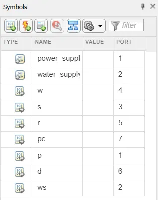
- Using the symbol pane the symbols are configured as input or output.
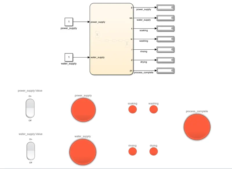
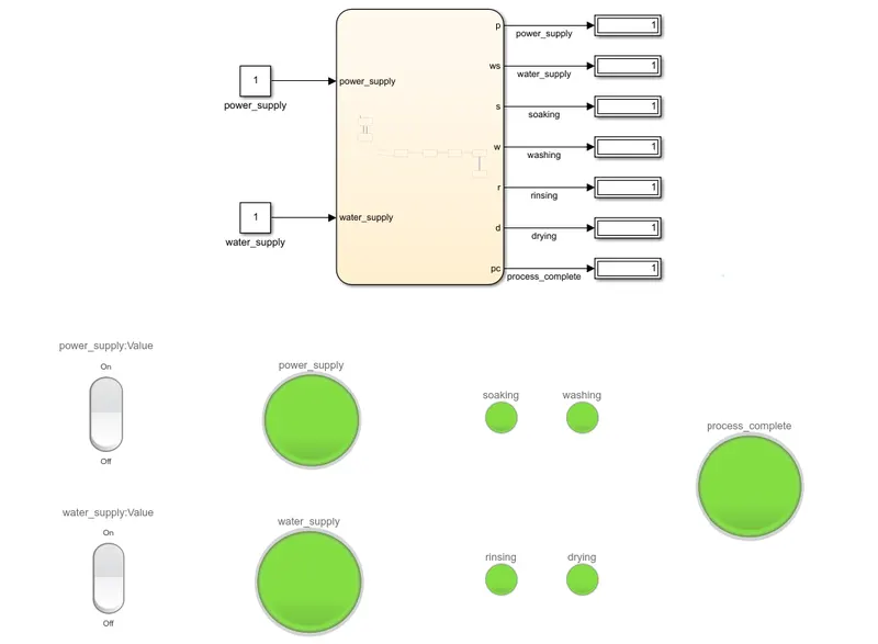
- Once the chart block is done, In the main model workspace the using simulink library, dashboard section, rocker switches and lamps are introduced.
- Rocker switched are used to toggle the availability of power and water. As per the stateflow logic when the two switches are turned on, then the process of washing is started.
- There are two lamps(LED's) are connected to these which are used to visualise either the switch is turned on or off.
- The configured in such a way that the light up green with condition is satisfied (turned on or completed process)
- The lamps are connected to the each individual process to make sure the process is completed.
- The inputs are given as constant which are connected to the switches provided and lamps(LED).
- The outputs are connect to the displays which are conned to the lamps(LED)
- The is simulation is run for 400sec to execute all the process
- Symbol pane:
- Output:
#2: Make a Simulink chart for the “Gear shift” logic:
- Theory:
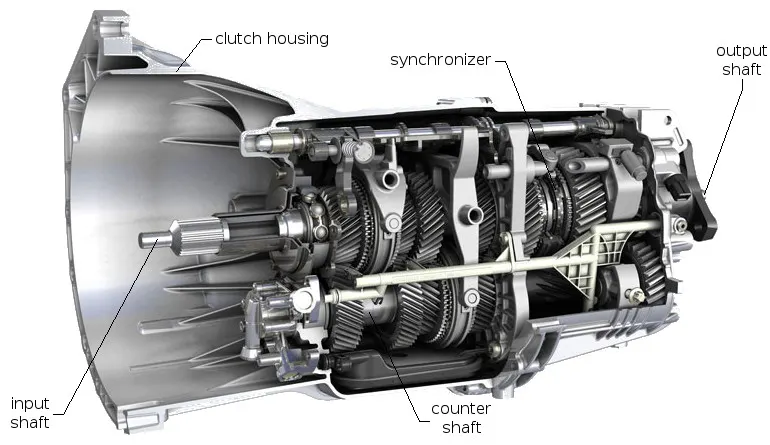
- A manual transmission also known as a manual gearbox a standard transmission used in motor vehicle applications. It uses driver operated clutch, usually engaged or disengaged by a foot pedal or hand lever for regulating torque transfer from the engine to the transmission and the gear selector can be operated by hand.
-
Working - In a gearbox the tertiary counter shaft counter shaft is mashed to the clutch with the use of couple of gears so the countershaft is alwaysin running condition. When the tertiary shaft is brought in contact with the main shaft by the use of meshing gears the main shaft starts to rotate according to the gear ratio. When thhe driver wants to change the gear he simply press the clutch pedal which disconnects the tertiary shaft with the engine and connects the main shaft with the tertiary shaft by another gear ratio by the use of gearshift lever.
- Objective:
-
Speed Range(kmph) Gear
0 to 15 1
16 to 25 2
26 to 40 3
41 to 60 4
Above 61 5
Give speed input while the simulation is running & display the gear number.
-
- Simulink Model:
- Chart Block:
- Procedure:
- Create a blank simulink model, create a chart block and define the state flow as per the given obejectives.
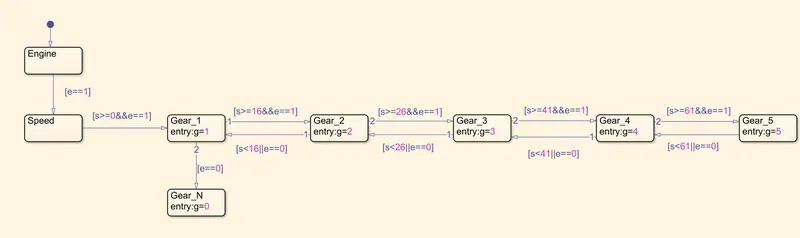
- The first state checks if the engine is on or off. If the engine is turned on, then it procedes to the next state which is speed.
- Depending on the input given to the chart and the conditions given the logical operators are used.
- For accleration condition (incresing speed), 'and' logical operator is used. To make sure that the engine is turned on and speed criteria is met.
- For deceleration condition (reducing speed), 'or' operator is used. So there is a down shift if speed is reduced or engine is turned off.
- Neautral gear is indicated by the number 0.
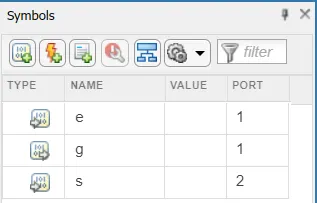
- Using the symbol pane the symbols are configured as input or output.
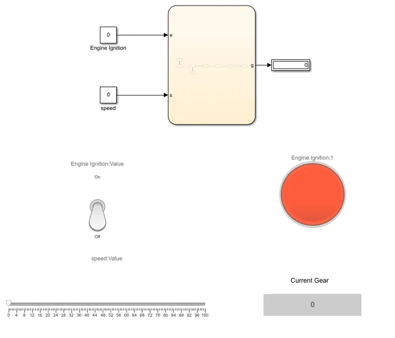
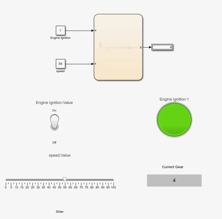
- Once the chart block is done, In the main model workspace the using simulink library, dashboard items are introduced.
- For engine ignition, a toggle switch is used and a lamp is also is connnected to indicate the position of switch. for speed, slider block is used for values of 0 to 100.
- For gear indication a display is used from dashboard libary is used and connected to the output of the chart.
- The simulation runtime is given as infinite.
- Symbol pane:
- Output:
Conclusion:
- Using State flow control logic of washing machine is executed
- Using the state flow "gear shift" logic is simulated.
Simulink Files: