Mechanical design of Li-ion battery pack
Objective:
Battery pack capacity: 18 kWh
Cell: ANR26650M1-B
Prepare a detailed battery pack drawing along with its enclosure. State your assumptions.
Assumptions:
The voltage of the battery pack is estimated to be 300V.
No limitations are dimension of the battery pack
Given Cell: ANR26650M1-B
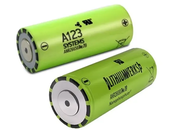
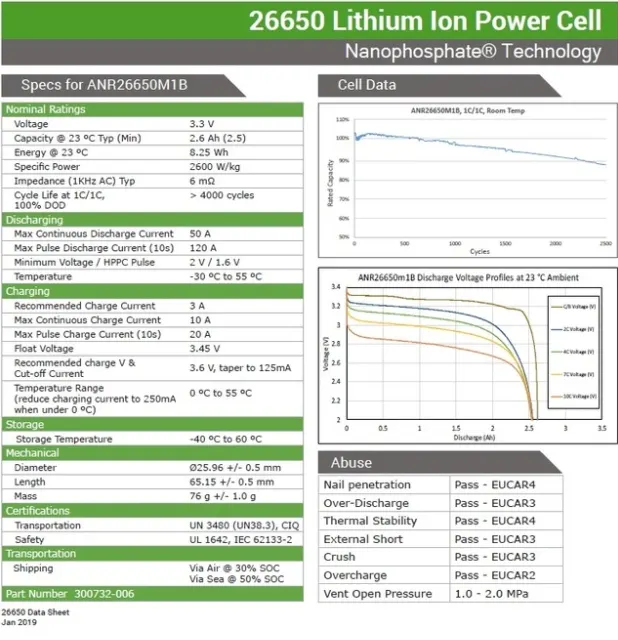
Given cell is a 3.3V 2.5Ah Lithium Iron Phosphate Battery
Following image shows the specifications of ANR26650M1-B cell
Battery Pack Specifications:
Energy of battery pack: 18kWhr
Voltage of battery pack: 300V
Calculations:
Max Battery Pack capacity is given by the following formula
Max Capacity = Pack Energy (Whr)/ Pack Voltage (V) = 18000/300 = 60Ahr
Number of cells in series = Pack Voltage / Cell Voltage = 300/3.3 = 90.90 = 91 (as a fraction of a battery is not possible)
Number of cells in parallel = Pack Capacity / Cell Capacity = 60/2.6 = 23.07 = 24 (as a fraction of a battery is not possible)
Therefore, the battery pack configuration is 91S24P
Total Number of cells required = 91*24 = 2184 cells in total
Cell dimensions:
Cell Electrical Connections:
Internal Connections:
- Nickel strips welded to the cell terminals or the casing are typically used to connect low-power cells.
- Soldering is not advised because it might cause enormous, uncontrolled quantities of heat to be applied to the battery components, potentially damaging the separators or vents, which are usually made of plastic.
- Modern computer-controlled resistance welders enable for considerably more accurate welding process control, controlling the amount of heat delivered to the battery while also localizing the heat to a tiny targeted region.
- Welding also creates a more durable and low-resistance junction.
- Interconnecting strips frequently have complicated forms and profiles that may be stamped out of flat strips using a progressive die.
External Connections
- The current to be carried, the frequency with which the battery may be connected and detached, and the design of the circuit to which the battery will be attached determine the kind of terminals or connections to external circuits.
- Gold plated contacts are the terminals of choice for connections that are susceptible to frequent insertions in low-power circuits.
- Gold is a long-lasting metal with minimal contact resistance and no oxidation. Low-power applications can also employ flying leads with spade terminals or Snap-On studs. On pouch cells, metal tabs are also utilized.
- To guarantee a stable connection, high-power terminals are typically threaded metal studs.
- Shrouded terminals on high-voltage batteries may be required by safety regulations to protect the operator from being accidentally exposed to harmful voltages or the battery from being short-circuited.
- To avoid connecting to improper charges or loads, keyed or terminals or connectors are also recommended.
Spot Welding
- In the automobile sector, spot welding is one of the oldest and most commonly utilized welding techniques.
- Resistance spot welding has the benefit of not requiring filler materials or gases, as well as being easily mechanized for industrial production applications.
- It is a reasonably inexpensive and quick joining method that can also achieve a high degree of quality control.
- Thin sheets can be properly connected, but big nuggets are difficult to produce using spot welding.
- The material to be welded and the desired weld result decide the electrode alloy to be used. Copper-based alloys are the most widely used electrode materials.
- The metallic strips used for battery connections are constructed of a variety of materials and are spot welded.
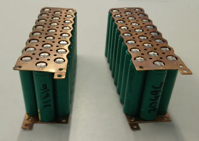
Because nickel can readily spot-weld the cells, and copper can tolerate the high current without producing a significant voltage loss, as a result, a copper bus plate with a short nickel tab can be employed to cover the cell.
Battery Pack Design:
- The design of the outer package or housing of the battery depends to a great extent on the components.
- It has to accommodate and the physical protection it has to provide for them.
- These components are not just the cells, but also protection devices, electronic circuits, interconnections and connectors which must all be specified before the final battery case can be designed.
- For high-power, high-energy batteries robust packaging is required for safety reasons.
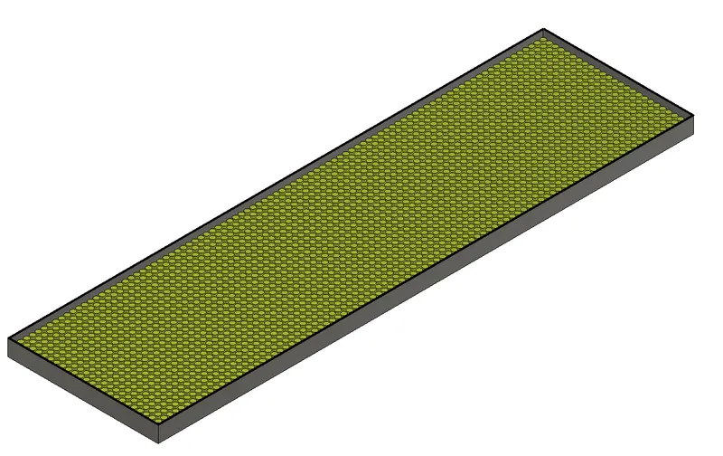
Estimated Dimension of battery pack
Estimated Length of Battery Pack:
(No of cells in series * cell diameter) + (no of cells in series -1) * Clearance between cells (4mm) + 60mm (clearance for first and last cell from casing)
= 91*26 + (91-1)*4 + 60 = 2786mm
Estimated Breadth of Battery Pack:
(No of cells in parallel * cell diameter) + (no of cells in parallel-1) *4mm + 60mm (clearance for first and last cell from casing)
= 24*26 + (24-1)*4 + 60 = 776mm
Estimated Height of Pack
Height of cells + 2 * 1mm of bus plate + space for ventilation
66 + 2*1 + 12 = 80mm
Battery Enclosure
Considering 5mm of Al 6061
Battery Enclosure Dimensions
Length = 2786+10 = 2796mm
Breadth = 776 + 10 = 786mm
Height = 80 + 10 = 90mm
Volume = `V_o-V_i` = (2796 * 786 * 90) - (2786 * 776 * 80) = 24834160 `mm^3` = 24834.16 `cm^3`
Density = 2.7 `g/{cm^3}`
Mass = Volume * Density = 24834.16 * 2.7 = 67052.232 gm = 67.05 kg
CAD model (only cells and enclosure)