Week 9 - Project 1 - Door Applique Design with Engineering Features
Aim
To create a solid surface and add locator and heat stakes for given class A Surface.
Process
- Creat a tooling axis
- Design B Surface
- Design C surface
- Design locators
- Design Heat Stakes
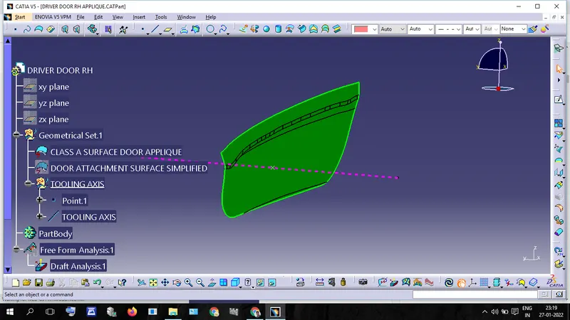
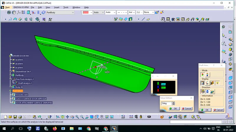
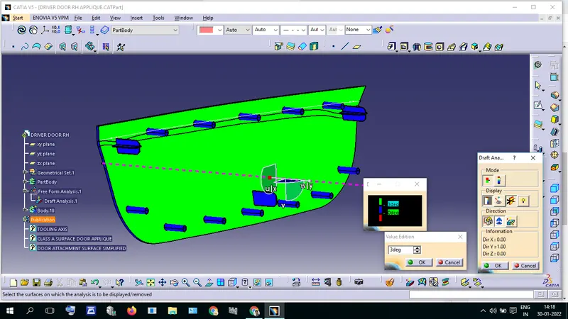
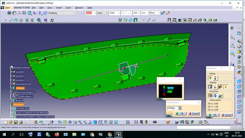
- Draft Analysis
Creat a tooling axis
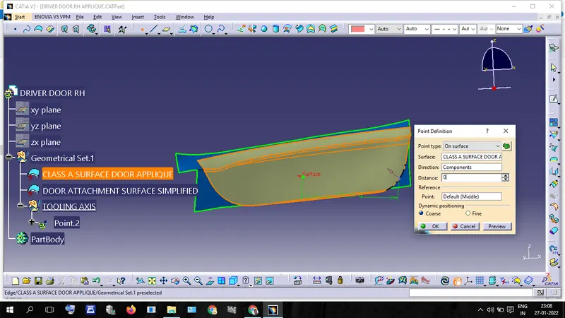
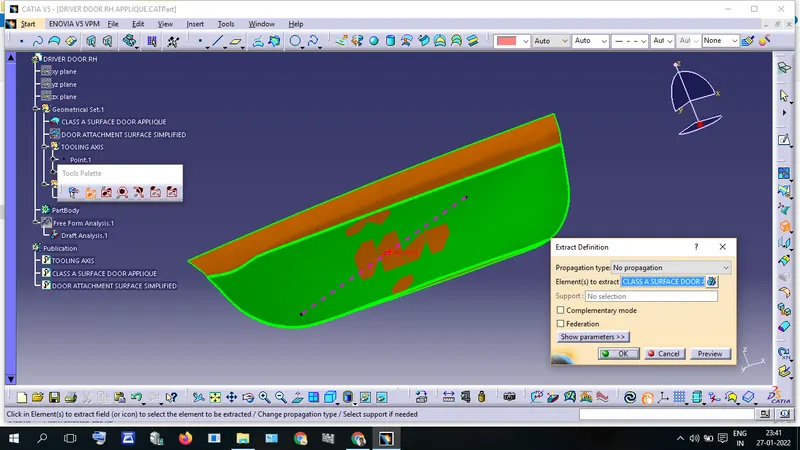
Draw a point in the given class of Surface using Point Defenition.
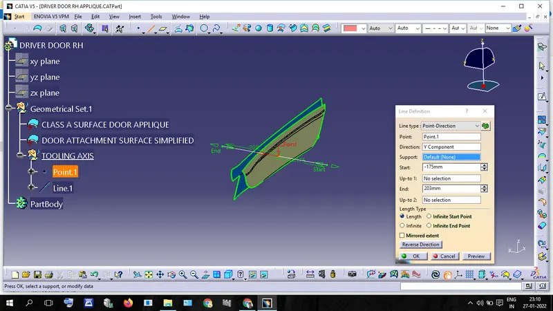
Draw a line using the point, this is the tooling axis.
Check the Draft analysis

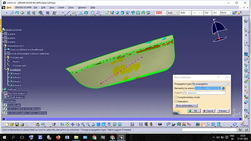
Design B Surface
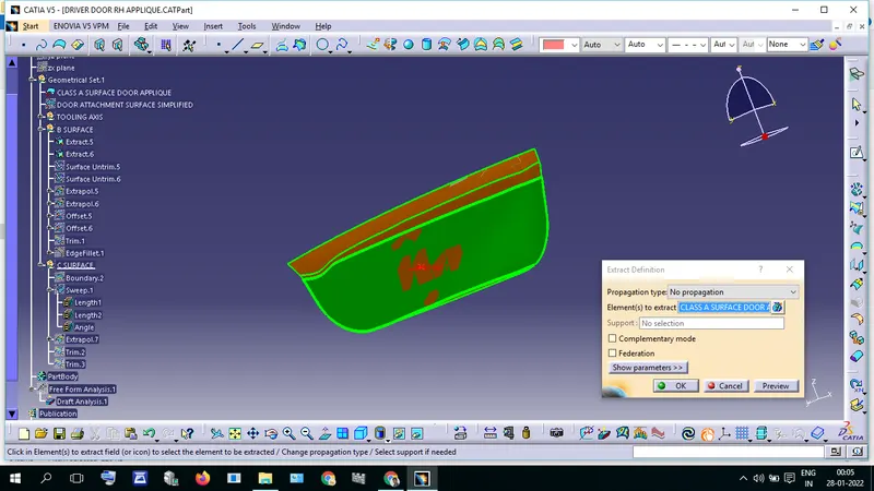
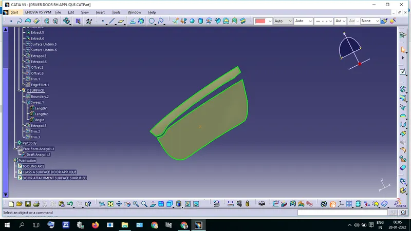
Extrude the patches in class a surface. and extrapolate that surface,
after extrapolating the surface gives an offset value of 2.5mm.
and trim the offsets surfaces. Now we get B surface.
Design C surface
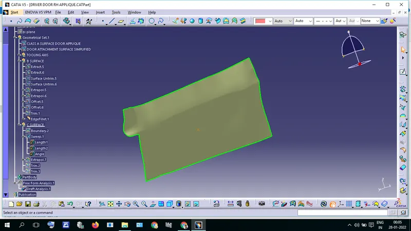
Extrude the boundary of Class A Surface
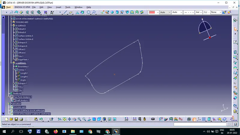
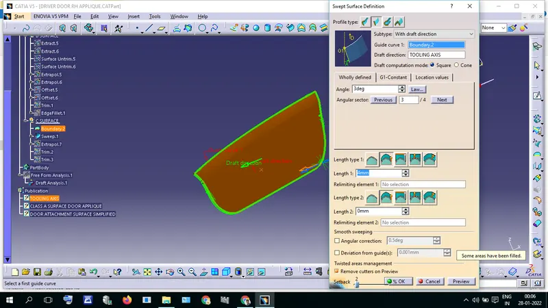
Use Swept Surface Definition and create a boundary surface
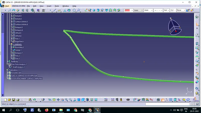
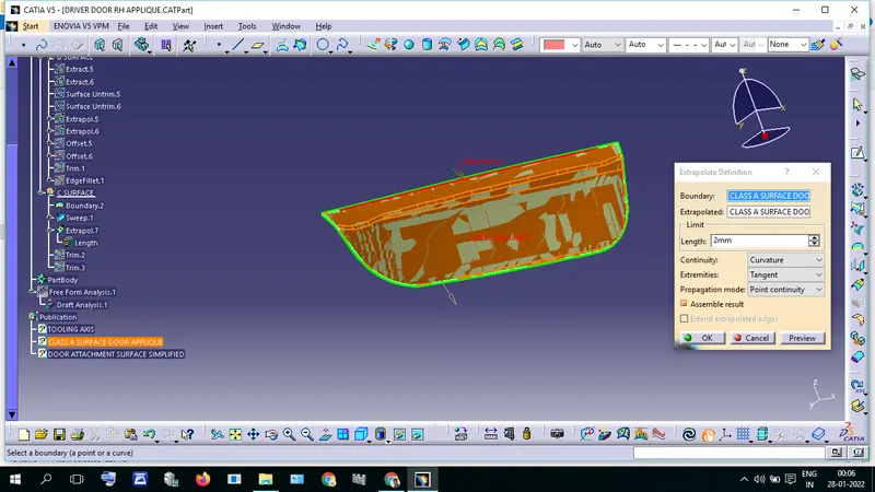
Extrapolate the Class A Surface with the value of 2mm for Trim with boundary Surface. Trim the Class a surface
with Boundary Surface and B Surface. Now we get a C surface. After Creat the C Surface, convert it into solid.
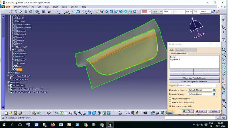
Design locators
Draw a Sketch live below the given image.
and Convert this sketch into a Solid Using Pad tool.
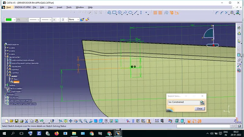
Give sufficient draft and Fillets.
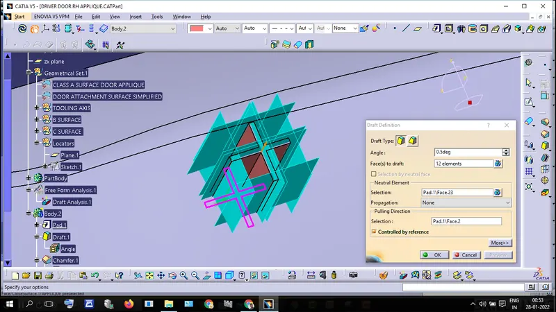
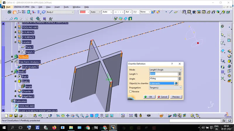
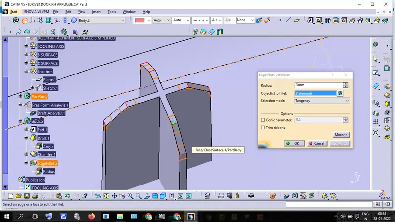
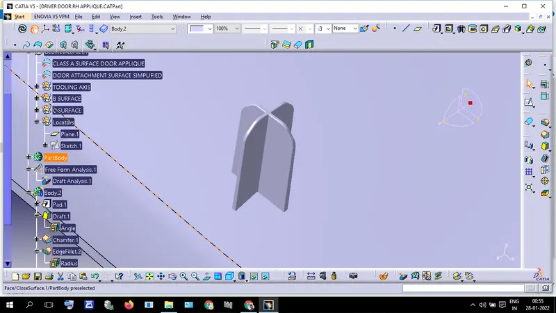
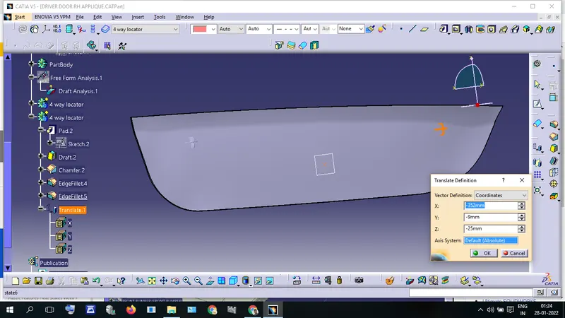
Create another Locator and translate it to another location of Part.
Design Heat Stakes
Extrude the boundary of surfaces and give parallel lines using the Parallel curve tool.
Creat Points on the parallel line Using Point & Planes Repetition tool.
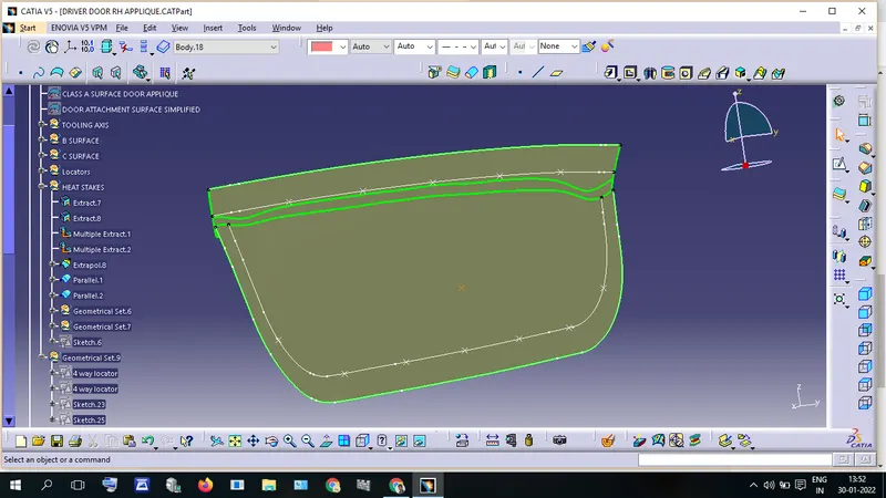
Draw a Position Sketch of the Heat Stake.
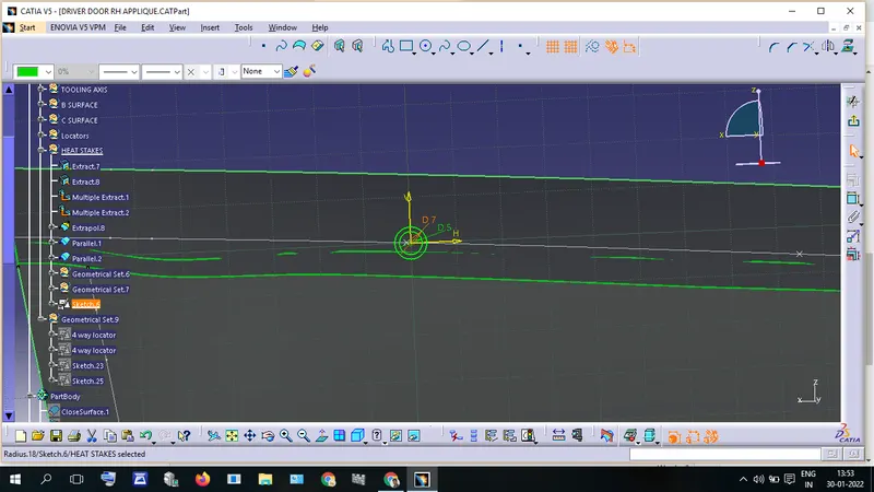
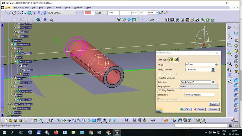
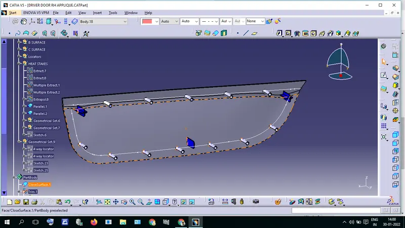
Give Pad Command to the created sketch and give Drafts.

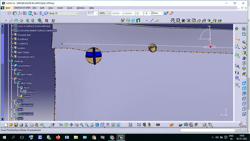
Draft Analysis
Result
Tooling Axis has Created
B surface has Created
C Surface has Created
Locators have Created
Heat stake has Created
Draft Angle has Analysis.