Wiring harness design in CATIA V5 - 3D modeling Week 2 Challenge
Parameter Required for Electrically Define the Connector
- Geometry Parameters - Points & Co-ordinate system (Axis)
- Connector connection points - This point connects one connector to another.
- The harness bundle entry point - defines where the harness bundle segment point will end when routed to the electrical connector.
- Cavity connection point - This point defines the connection of a connector to a connector clip. This only applies to connectors that have the mounting feature for a connector clip. This is the optional Parameter This Point is only needed when a clip mount is required.
Define the Connector Electrically
I have downloaded Deutsch DT06 – 08SA Connector using this link ( https://www.te.com/usa-en/product-DT06-08SA.html)
1. Geometry Parameters
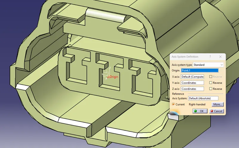
Create a Connector Axis System on the Front face of the Deutsch DT06 – 08SA Connector.
- This Connecctor Axis System should be the front face of the Connector
- Axis System Point should be in the center of the front face of the connector. with coordinates of (0.0.0)
- This Axis System used to connect the connector with another connector or other electrical components
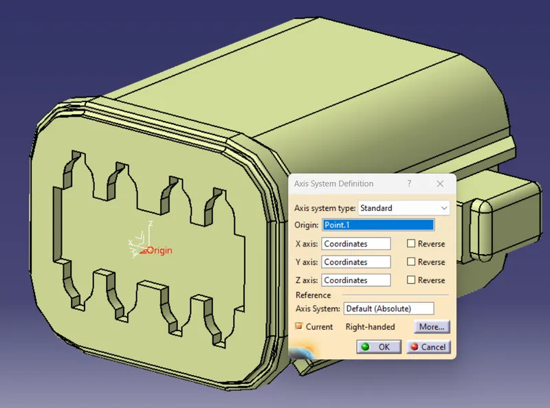
X-axis should be pointing toward the locking System
Y-axis should be pointing in the direction of the front face of the connector. (mating direction) same Direction as the hardness of the connector
Z Axis Should be pointing across from the connector from left to right.
Hardness Bundle Entry Point
- The Handness Bundle Entry point should be the center of the hardness bundle entry side, it might always back side of the connector
- Create a point center of the connector's back side.
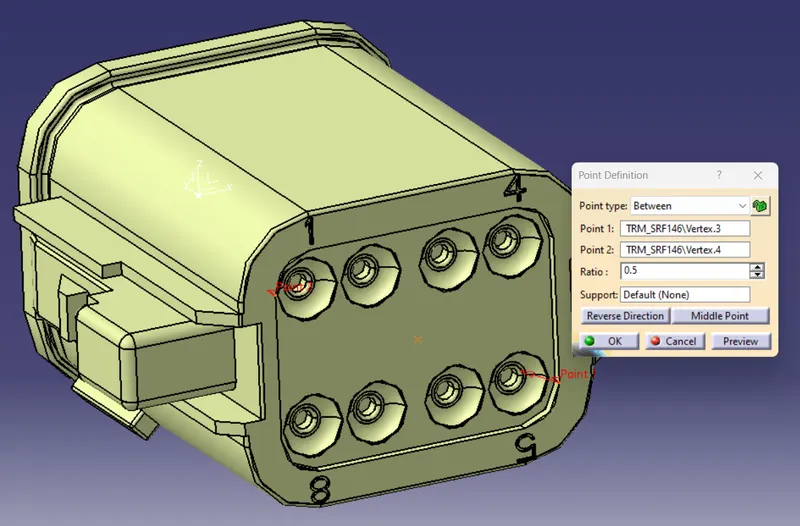
we have creat all Geometry Parameters in this connector.
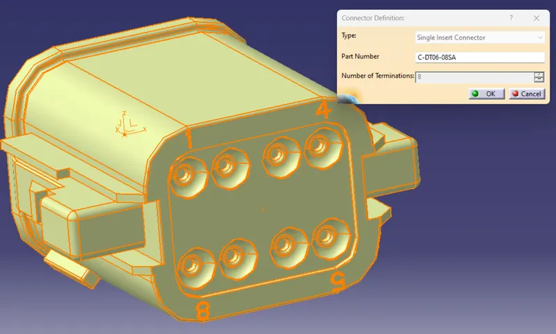
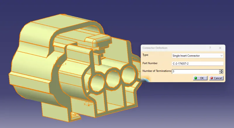
Use Define Connector  Commad to define the Part file as Electrically.
Deutsch DT06 – 08SA connector has 8 terminals so we gave the "Number of Terminations" as 8.
Some Connector has 2 terminal, and some connector has 4 terminal so we should give a value for "Number of Terminations" based on the connector terminal Quantity
if the connector has 3 terminal we should give "Number of Terminations" as 3
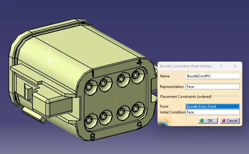
2. Connector connection points 
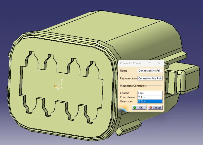
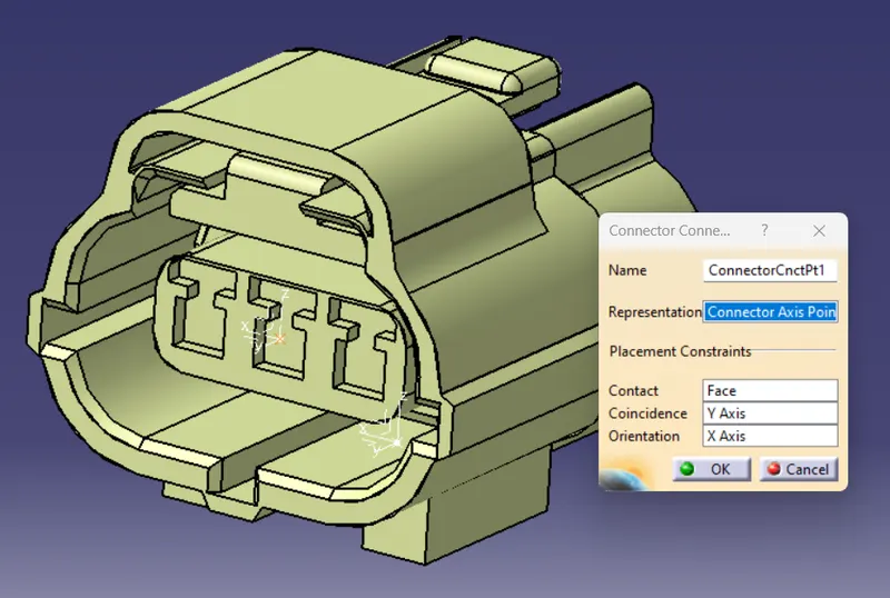
The connector Connection point command is used to connect the connector with this male or female part. or another connector
Define "Connector connection point"
Now let's define the connector connection point.
- Select the connector connection point icon from the workbench.
- Select the connector you want to add the connector connection point to.
- In the connector connection point previously created.
- In the connector connection point definition box select the contact and then select the front face of the connector.
- In the connector connection point definition box select the coincidence and then select the Y axis of the axis system that was previously created.
- In the connector connection point definition box select the orientation and then select
- the X axis of the axis system that was previously created.
- Select OK.
3. The harness bundle entry point - defines where the harness bundle segment point will end when routed to the electrical connector.
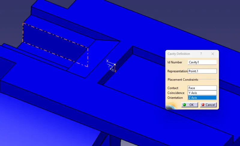
Cavity connection point -
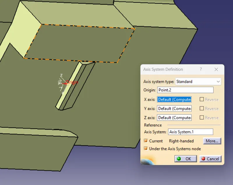
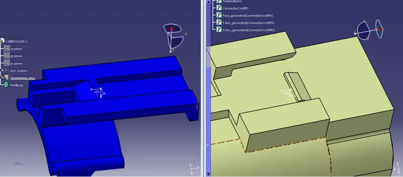
This point defines the connection of a connector to a connector clip. This only applies to connectors that have the mounting feature for a connector clip.
This is the optional Parameter This Point is only needed when a clip mount is required. so we download a Connector & Clip
Tyco 174357-2 Connector - (https://www.te.com/usa-en/product-2-174357-2.html?source=header-match)
Tyco 85229-1 Clip – (https://www.te.com/usa-en/product-85229-1.html?q=85229&source=header)
Connector Axis System Creation
Cavity Axis System Creation

Electrically Define the Connector
Define Connector Connection Point
Create Cavity Connection Axis
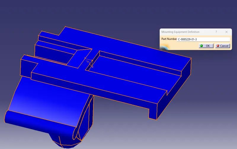
Electrically Define the clip
Use the "Define Mounting Equipment  " Comment to
Define Cavity 
Create a new Product File
Add the "Connector" and "Clip" into the Product file
Go To "Electrical Assembly Desing" Work Bench
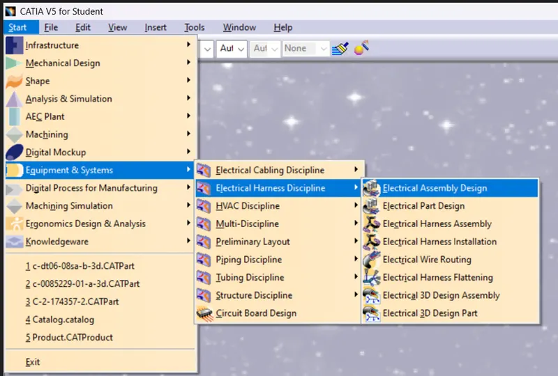
use the "Connect Electrical Device  " Command to Connect the Connector and Clip
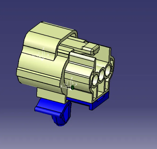
We have defined the Connector cavity Connection point and also connect the connector cavity point with the clip cavity
Catalog Creation
File -> New -> Catalog Document
use the "Add Family"  Command
and create a new family
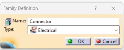
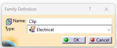
choose the necessary Type, we choose Electrical
Give the name to the family
we have created two Families for Connector & Clip
Save the Catalog to the particular folder
close the Catalog file
Open the connector and Clip Catia Part Files.
use "Store Device"  Comment
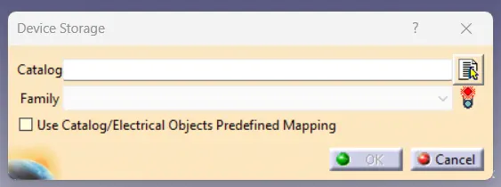
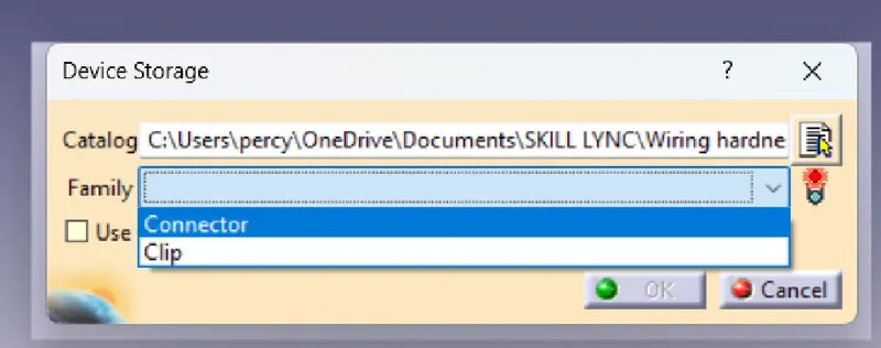
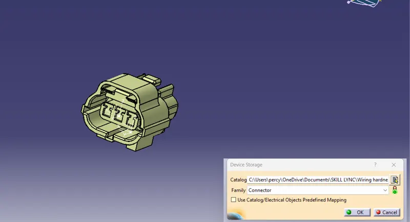
select the Catalog where you save the file
and choose the respective family
and click ok
the file will store in the Catalog