Wiring harness design in CATIA V5 - 3D modeling Week 4 Challenge
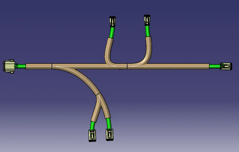
Q1. Route the following harness layout in Electrical workbench. Make assumption for harness bundle diameters. Use Following connectors as shown in layout diagram.
Add protective covering on all branches connected to DT06-2S & DT06-4S connectors. Keep end extremity at 30mm (from connectors end)
Download connector 3D data from www.te.com
- DT06-4S
- DT06-6S
- DT06-2S
- DT06-08SA
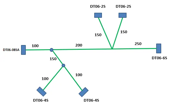
Procedure:
- Download connector 3D data from www.te.com
- Electrically Define the Download Connectors in CATIA "Electrical Part WorkBench
- Create New Product "Assembly_Geometrical_Bundle"
- Insert the Connector into "Assembly_Geometrical_Bundle"
- Arrange all connectors in their respective position
- Use, The"Multi breathable document"
 command to Routes the bundles between connectors.
 - After routing the bundle between connectors Give Production Covering to the connector "Use Production Covering"
 Command to add Production Covering to Bundles and give End Extremity about 30mm for each connector.
Define Connector Electrically
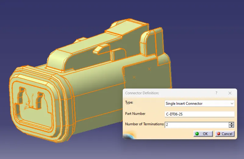
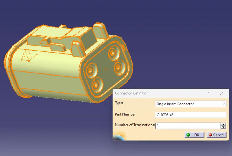
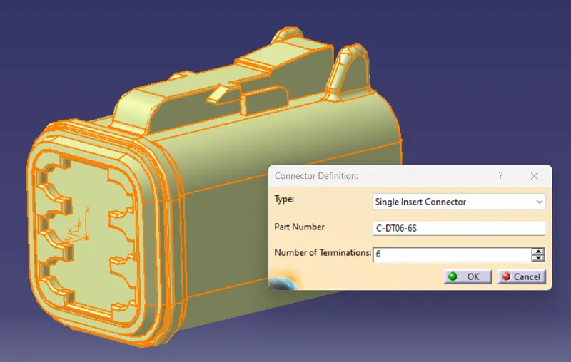
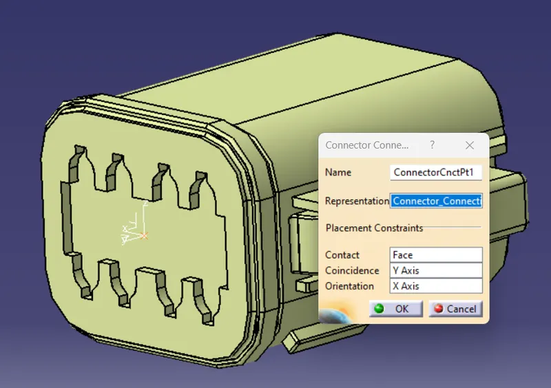
Define Connector Connection Point
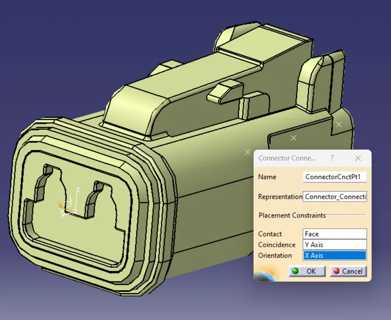
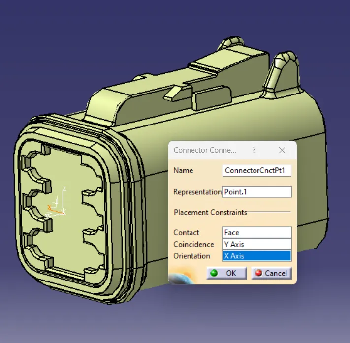
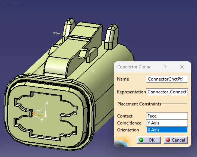
Define Bundle Connection Point
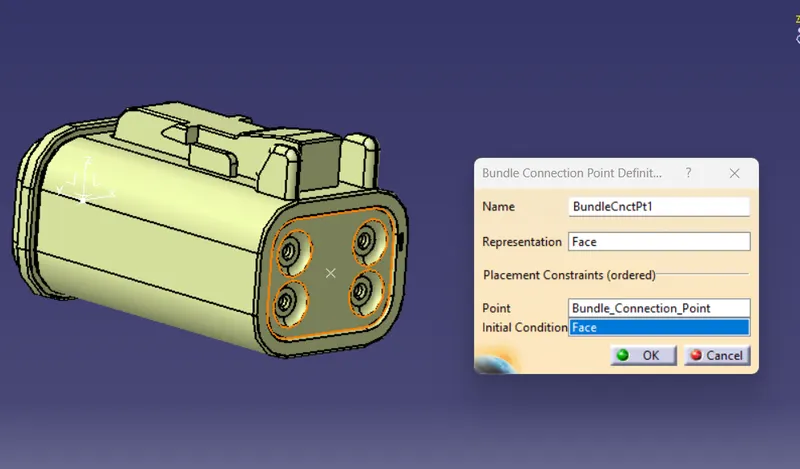
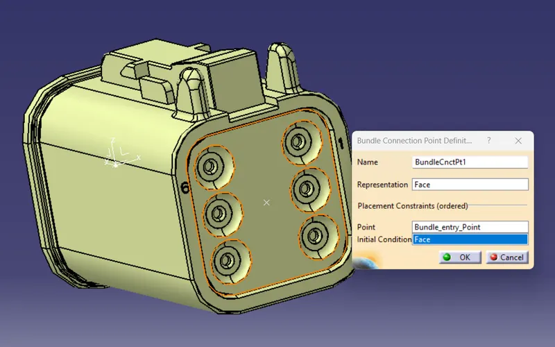
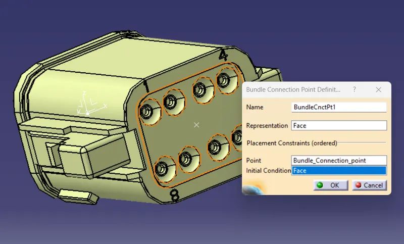
Arrange Connectors & Route the Bundles
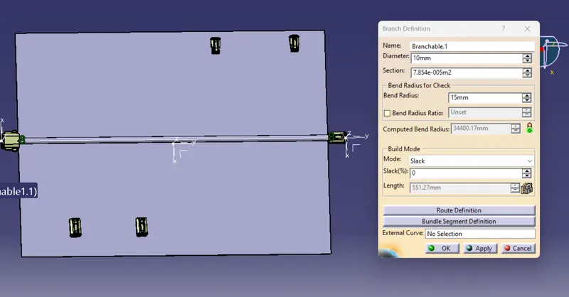
Create a "Branch Point" In Between Bundle
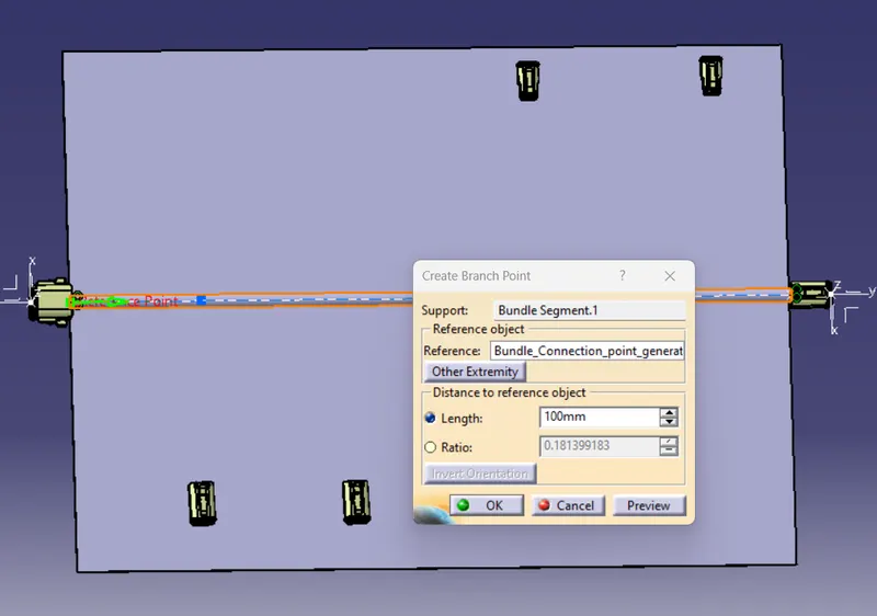
Create a new Bundle Route from Branch Point
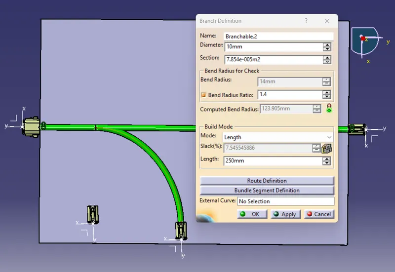
Create a "Branch Point" In Between Bundle
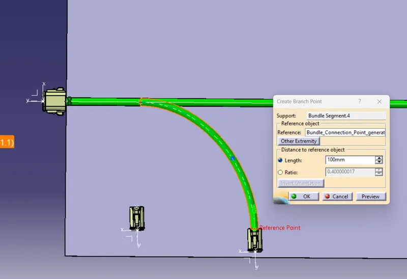
Create a new Bundle Route from Branch Point
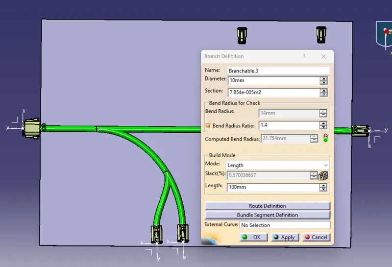
Create a another "Branch Point" In Between Bundle
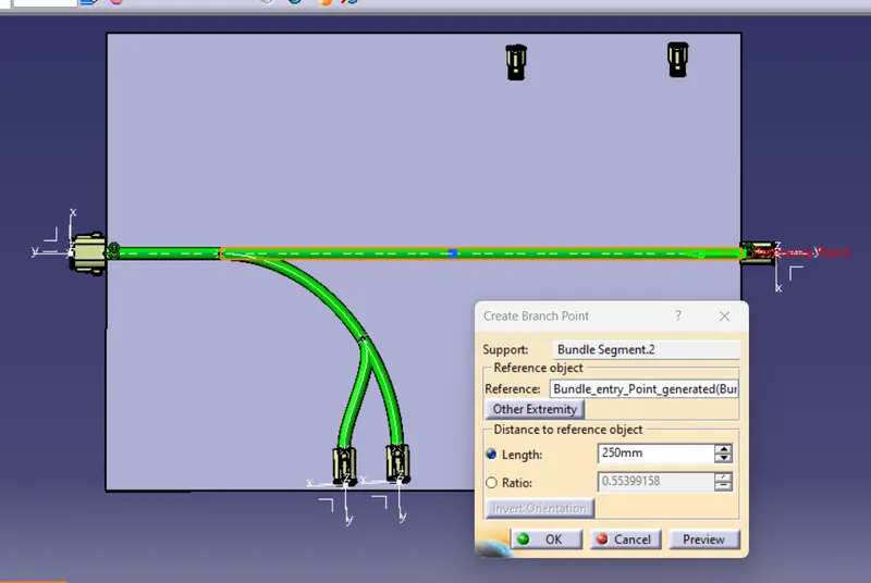
Create a new Bundle Route from Branch Point
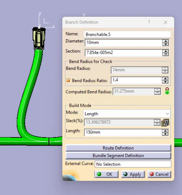
Create an Another Bundle Route from same Branch Point
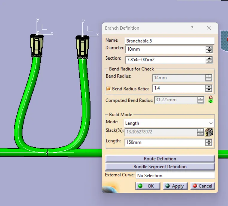
Add Production Covering From the Catalog
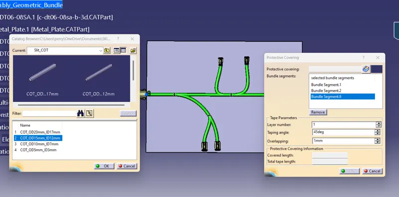
Production Covering Should be more than the Bundl e Dia.
Give End Extremity about 30mm
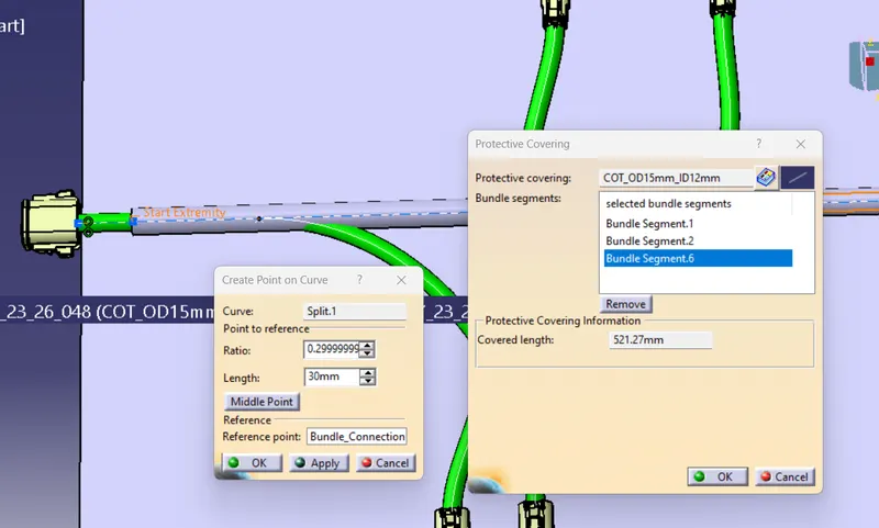
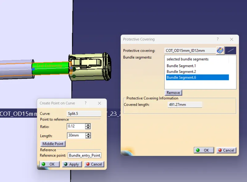
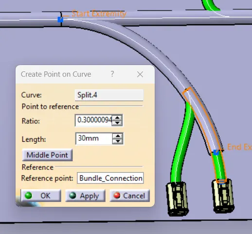
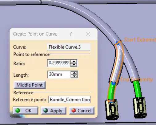
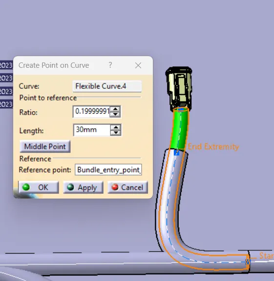
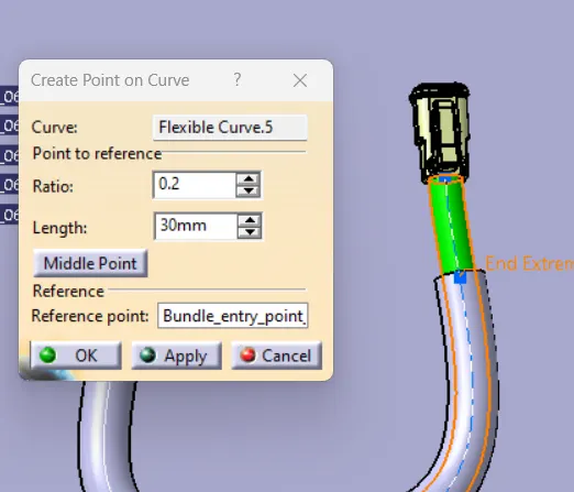
The Bundle had routed in between the connector and Branch Points added, and also production covering has given to this bundle Routing.