Wiring harness design in CATIA V5 - 3D modeling Week 5 & 6 Challenge
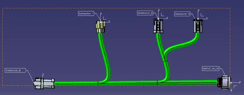
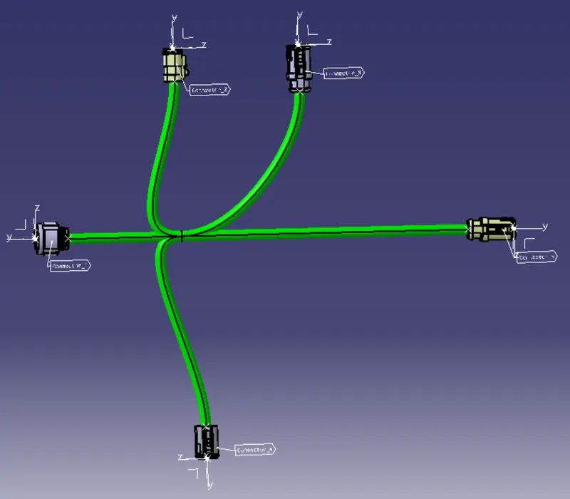
Q1. Route the following harness layout in the Electrical workbench. Make assumptions for harness bundle diameters. Use the connectors provided. After completion of routing,
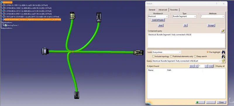
- Check the bundle Continuity. Add a snap of the result in the submission
- Add annotation to all connectors. Make assumptions for annotations like connect 1, 2, etc
- Check for the bundle warning. Add snap.
- Generate CAT.part of harness assembly and convert it in. igs format.
Procedures:
- Download Recommended Connectors from websites
- Create a Connector Entry Axis and Bundle Entry Point in all of the Connectors
- Define all of the Connectors Electrically.
- Create a Catalog and Add all of the Connectors to the Catalog
Hardness A Creation
- Create new Product Files for Hardness A and insert all Electrically Defined connectors for Hardness A.
- Electrically Define the Product using Geometrical Bundle
 Command
 - Place all connectors in their respective Position.
- Create bundle Segments between connectors using the Multi Branchable document
 Command.
 - Check the bundle Continuity (Edit -> Search->Advanced-> Workbench - Electrical -> Type- Bundle Segments -> Attribute-fully Connected, Choose Fale to identify the unlinked Bundles )
- Create annotation is used to Identify the Parts and Connectors in Hardness_B
- Check the Bundle Warning, If the bundle warning is visible Solve the Errors.
- Generate Harness_A as a CAT.part files
- Convert the Hardness_A as a .igs files
Hardness B Creation
- Create new Product Files for Hardness B and insert all Electrically Defined connectors for Hardness A.
- Electrically Define the Product using Geometrical Bundle Command
- Place all connectors in their respective Position.
- Create bundle Segments between connectors using the Multi Branchable document Command.
- Check the bundle Continuity (Edit -> Search->Advanced-> Workbench - Electrical -> Type- Bundle Segments -> Attribute-fully Connected, Choose Fale to identify the unlinked Bundles )
- Create annotation is used to Identify the Parts and Connectors in Hardness_B
- Check the Bundle Warning. If the bundle warning is visible Solve the Errors.
- Generate Harness_B as a CAT.part files
- Convert the Hardness_A as a .igs files
Hardness Assembly Creation
- Create new Product Files
- Rename as Hardness_Assembly
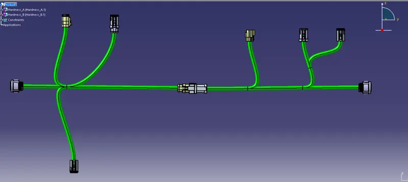
- Insert the Harndess_A and Hardness_B into Hardness_Assembly
- Goto Electrical Assembly Design Workbench. Use Connect Electrical DeviLog Outces
 Command to Connect the Connector 5 from Hardnes_B with Connector 6 from Hardness_A
 - Now Hardness_A and Harndness_B have been Connected.
Bundle Connectivity Check
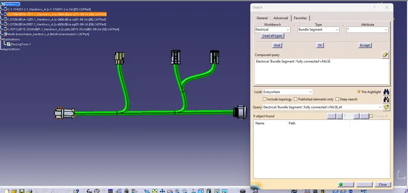
Annotation to all connectors