Photo Realistic Rendering
DESIGN OF AMERICAN CHOPPER
OBJECTIVE:
To design Americal Chopper using Solidworks Software, and make photorealistic view using Solidworks Visualise.
Introduction:
This Project explain the design of American Chopper Parts and its assembly using Solidworks, also explain photorealistic rendering using Solidworks Visualize.
Design methodology:
- Part Modeling
- Assembly
- Rendering
Description:
Part Modeling
In this Methodology, we design 3D Parts from 2D Sketch. 2D sketches Covert to 3D Using Features tools in SOLIDWORKS.
The following parts of American Chopper are designed in this methodology.
- Transmission Belt
- kick Stand
- Front Fender
- Rear Fender
- Chain
- Oil Tank
- Pedal
- Front Wheel
- Rear-wheel
- Front Fork
- Chassis
- Gas Tank
- Engine
Following Features Used.
- Boss Extrude
- Extrude Cut
- Revolve boss base
- Revolve Cut
- Fillet
- loft Boss
- Dome
- shell
- Combine
- linear Pattern
- Circular pattern
- Swept cut
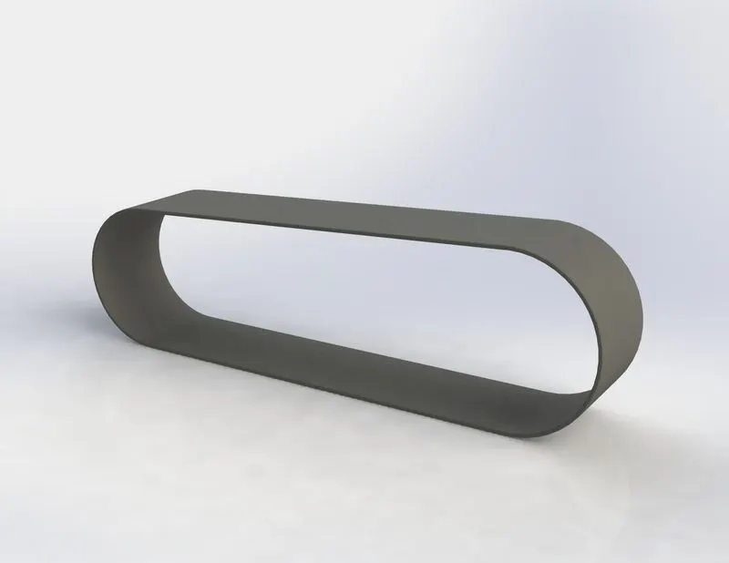
Transmission Belt
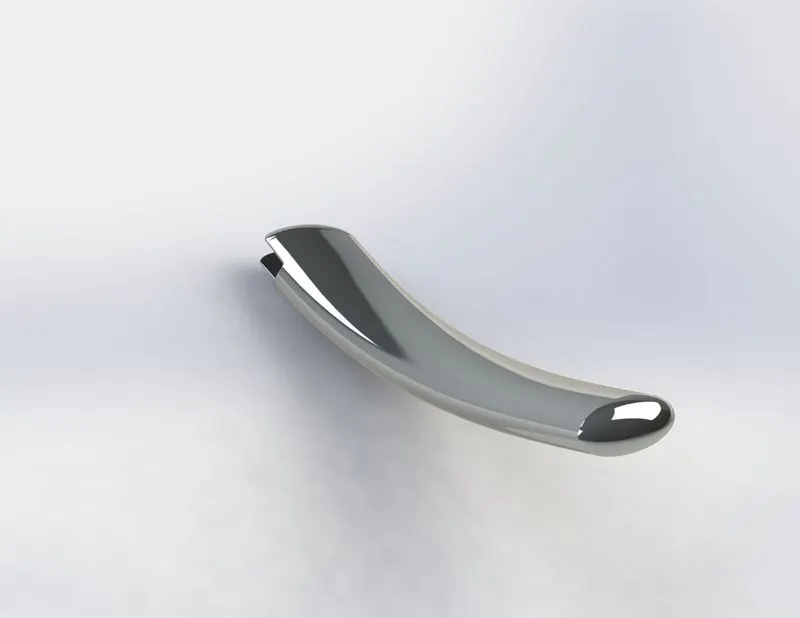
Kick Stand
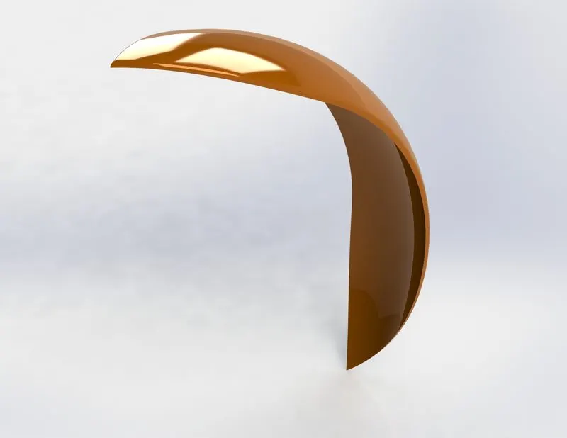
Front Fender
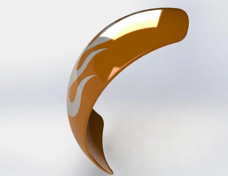
Rear Fender
Chain
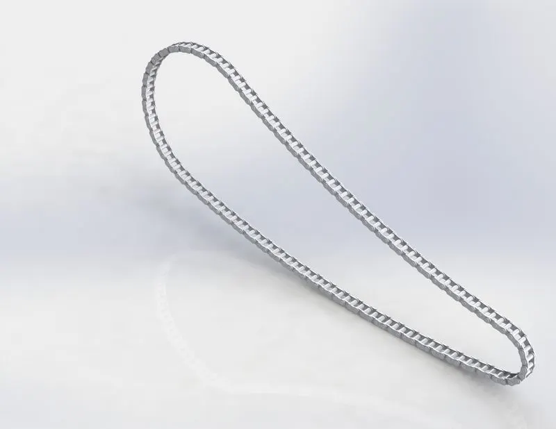
Oil Tank
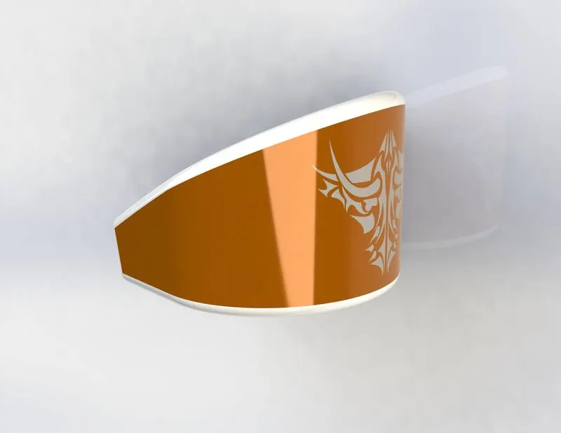
Pedal
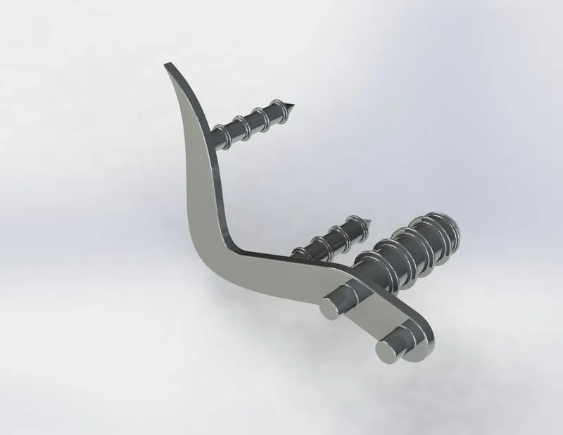
Front Wheel
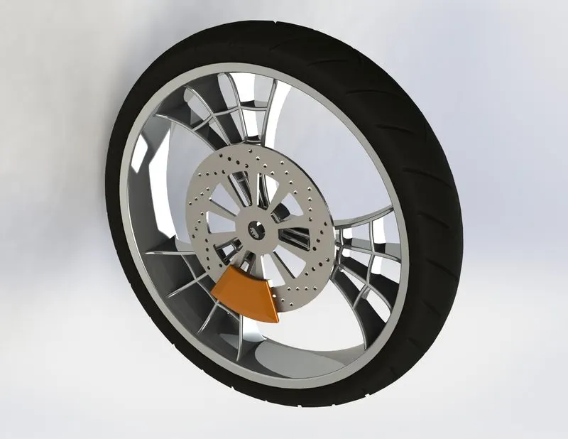
Rear Wheel
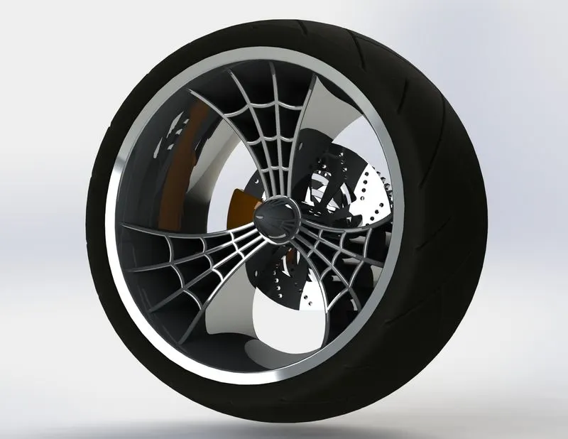
Front fork
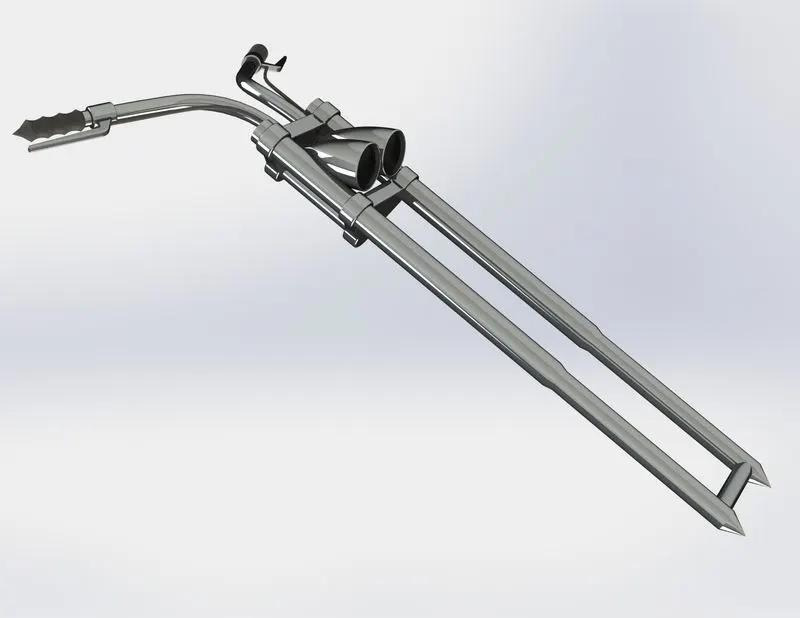
Chassis
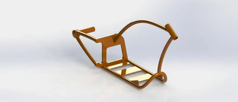
Gas Tank
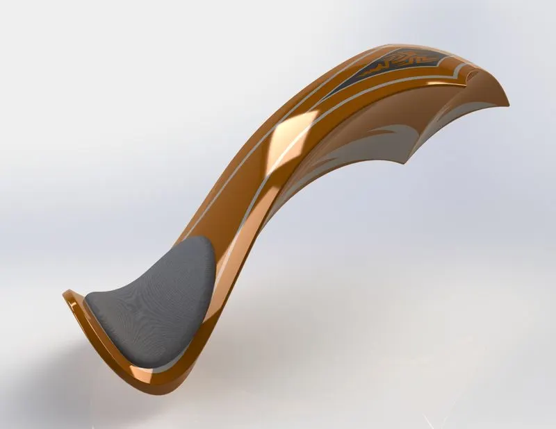
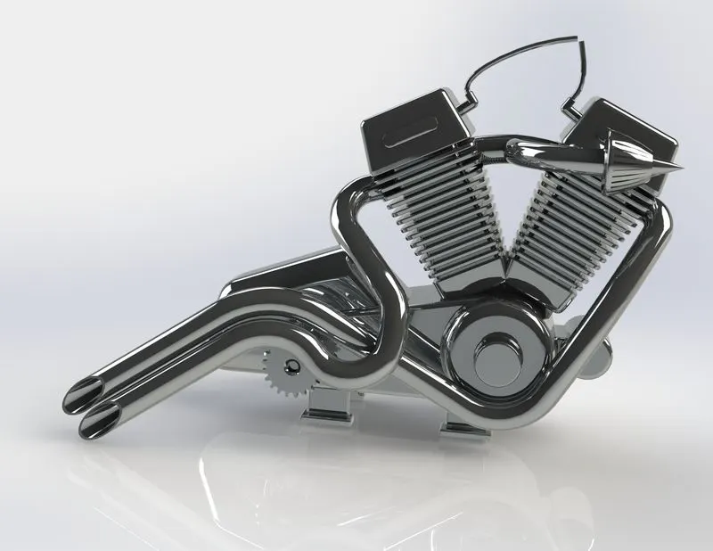
Engine
Assembly
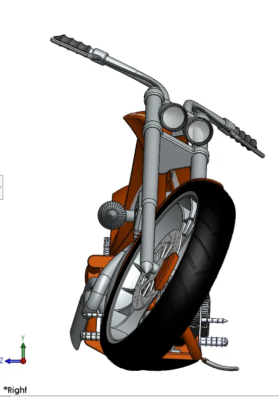
Assembly is creating a Complet Product. All parts of Americal Chopper are put together and assembled in their respective location and do fix with chassis Parts. each part If we need any correction in Parts during assembling, we can edit the part separately.
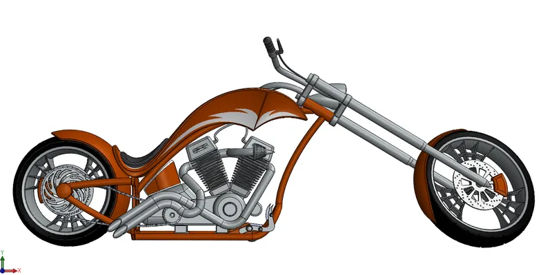
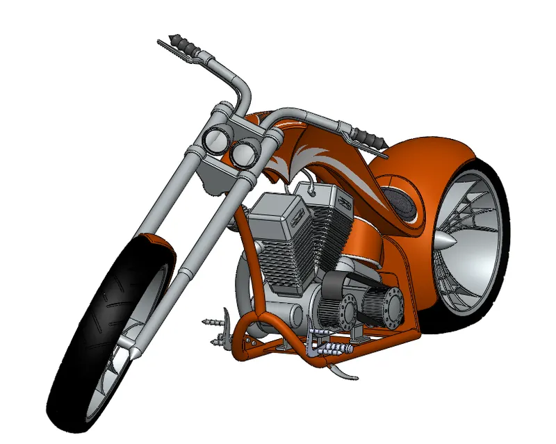
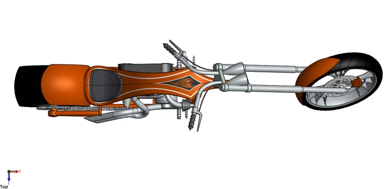
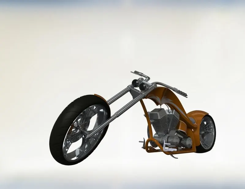
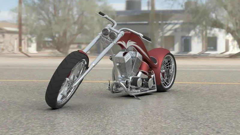
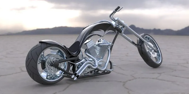
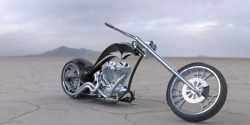
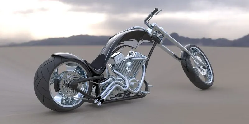
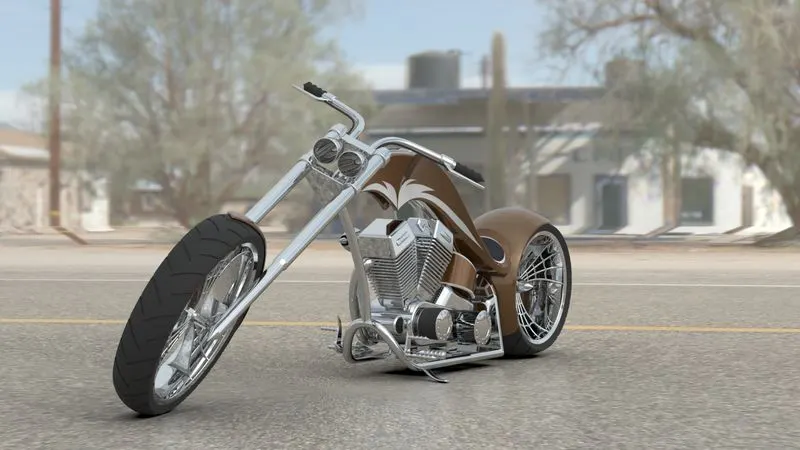
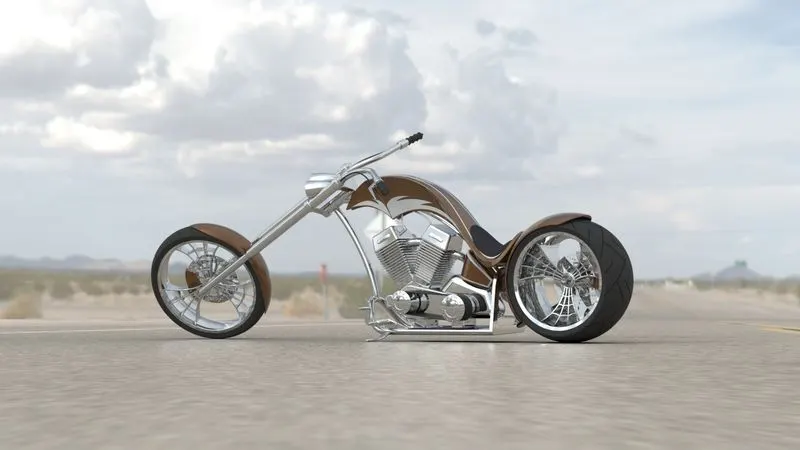
Final Render of American Chopper.
ConClusion
All the Parts of American Chopper were designed and Assembled using SOLIDWORKS, Rendered to Photorealistic Images using SolidWorks VISUALIZE.