Project 1
Aim:
To Route the Wiring harness on the Given Engine and Prepare a flattened view drawing in CATIA V5. Application of all Packaging rules and industry. Apply Protection coverings as required.
Prepare all necessary reports including clearance, Clipping/Clamping selection, Harness fixing requirements, Harness continuity, and Assumptions (if any) along with CATIA 3D data.
Procedures:
The engine is the Heart of the Automotive, So we have to create more than one harness going to Crate in this Project, they are
- Engine_Harness
- Engine_Chennal_harness_LH
- Engine_Channel_harness_RH
- Download Neccesory connectors, Clip, Clamp, and any other harness fixing parts from www.te.com
- Electrically Define the Downloaded Files in the Electrical Part of the Design Work Bench on CATIA_V5
- Create a new Product with the name of Assmbly_Engine_Hardness_Context
- Insert the Engine CAD Data into Assmbly_Engine_Hardness_Context
Engine_Harness Creation
- Create a new product file name of Engine_Harness and insert that into the Assmbly_Engine_Hardness_Context
- Electrically Define the Product Engine_Harness using the Geometrical Bundle Command
- Import the Electrically defined Connectors, Clamp, and necessary CAD files or Data into the Engine_Harness
- Place all connectors in their respective Position.
- Create bundle Segments between connectors using the Multi Branchable document Command.
- Check the bundle Continuity (Edit -> Search->Advanced-> Workbench - Electrical -> Type- Bundle Segments -> Attribute-fully Connected, Choose Fale to identify the unlinked Bundles )
Engine_Chennal_harness_LH
- Create a new product file name of Engine_Chennal_harness_LH and insert that into the Assmbly_Engine_Hardness_Context
- Electrically Define the Product Engine_Chennal_harness_LH using the Geometrical Bundle Command
- Import the Electrically defined Connectors, Clamp, and necessary CAD files or Data into the Engine_Chennal_harness_LH
- Place all connectors in their respective Position.
- Create bundle Segments between connectors using the Multi Branchable document Command.
- Check the bundle Continuity (Edit -> Search->Advanced-> Workbench - Electrical -> Type- Bundle Segments -> Attribute-fully Connected, Choose Fale to identify the unlinked Bundles )
Engine_Chennal_harness_RH
- Create a new product file name of Engine_Chennal_harness_RH and insert that into the Assmbly_Engine_Hardness_Context
- Electrically Define the Product Engine_Chennal_harness_RH using the Geometrical Bundle Command
- Import the Electrically defined Connectors, Clamp, and necessary CAD files or Data into the Engine_Chennal_harness_RH
- Place all connectors in their respective Position.
- Create bundle Segments between connectors using the Multi Branchable document Command.
- Check the bundle Continuity (Edit -> Search->Advanced-> Workbench - Electrical -> Type- Bundle Segments -> Attribute-fully Connected, Choose Fale to identify the unlinked Bundles )
Components Used:
- Connectors
- clips
- Production Cover
- Wire
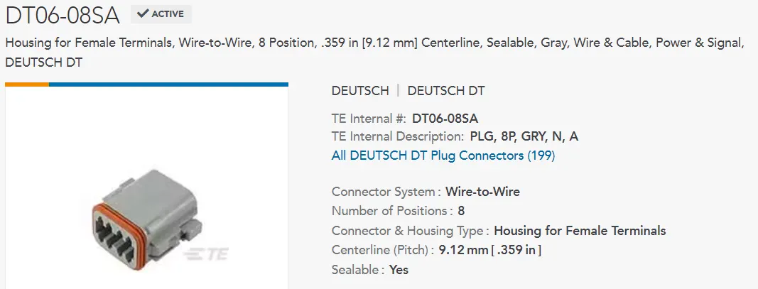
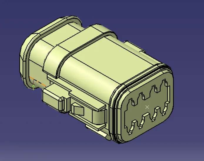
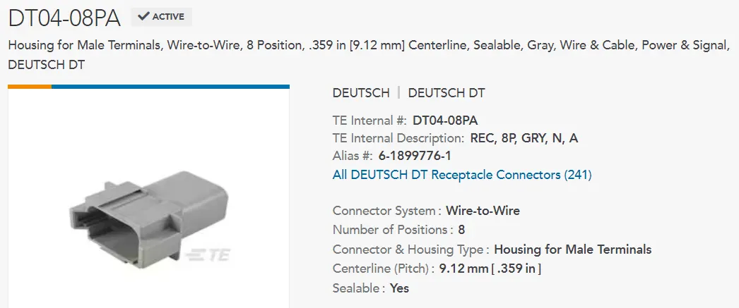
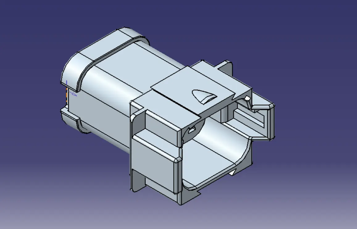
Connectors Used:
Connector 776438-4
Connector: 1563689-1
Connector: 282080-1
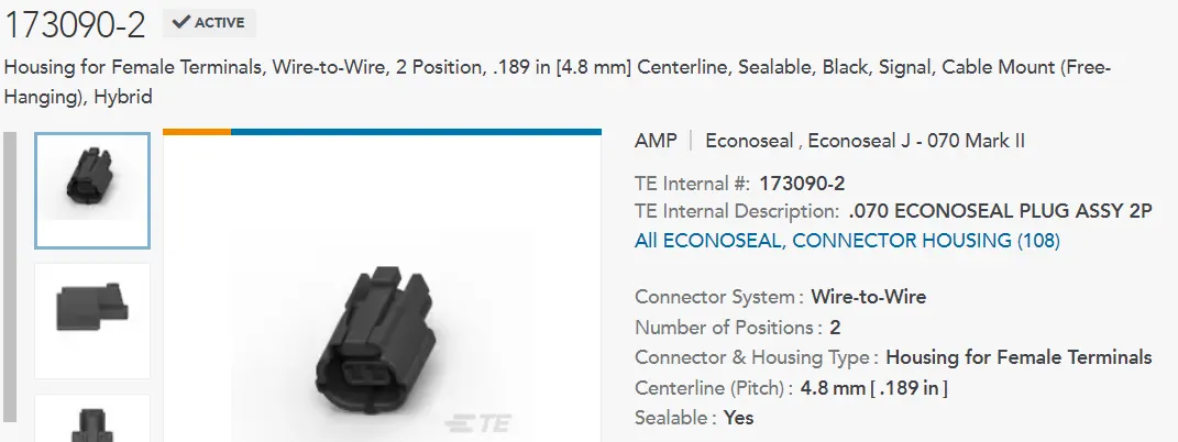
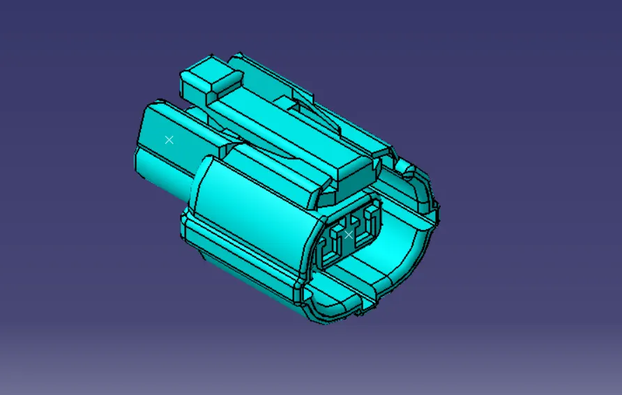
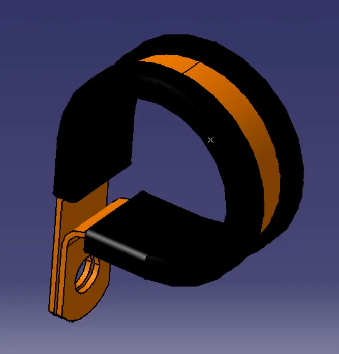
Used Clips:
-P Clamp
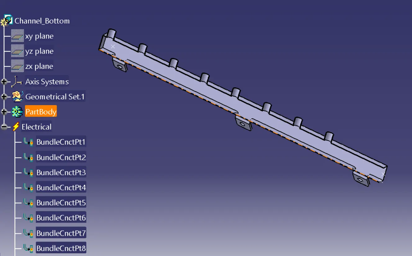
Guiding_Channel
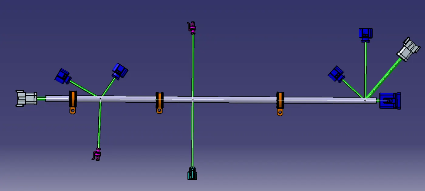
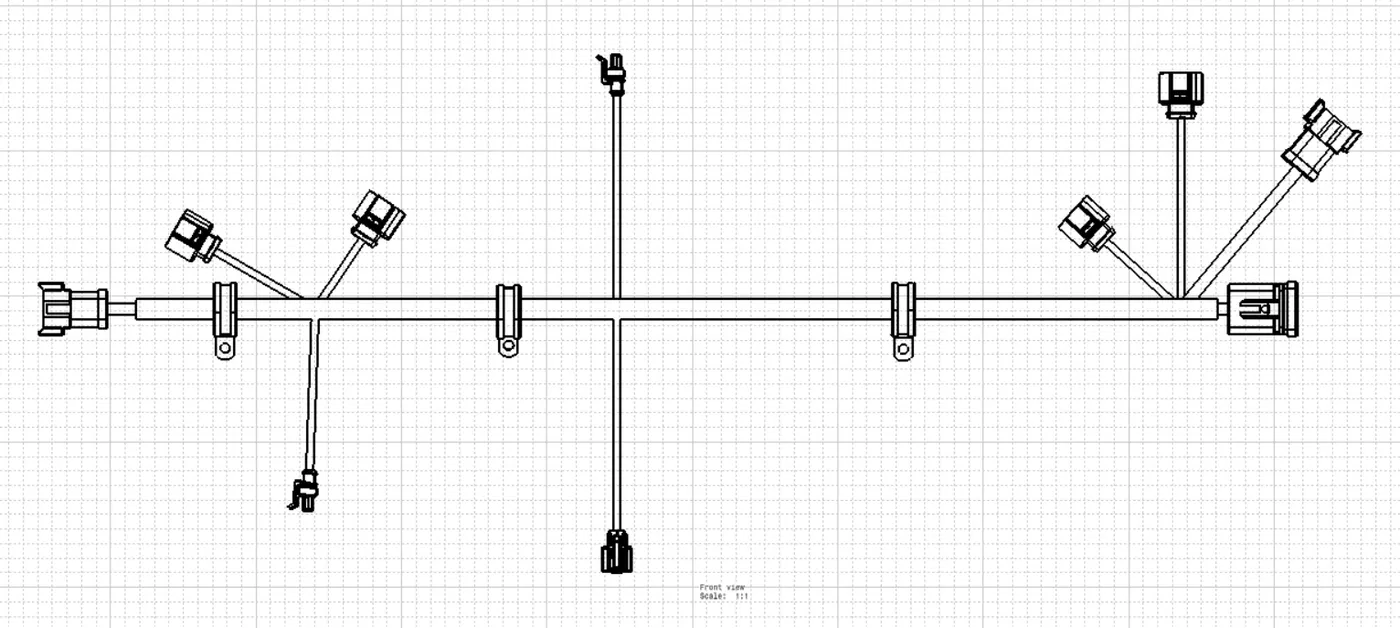
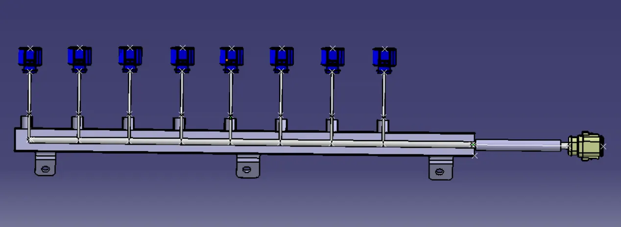
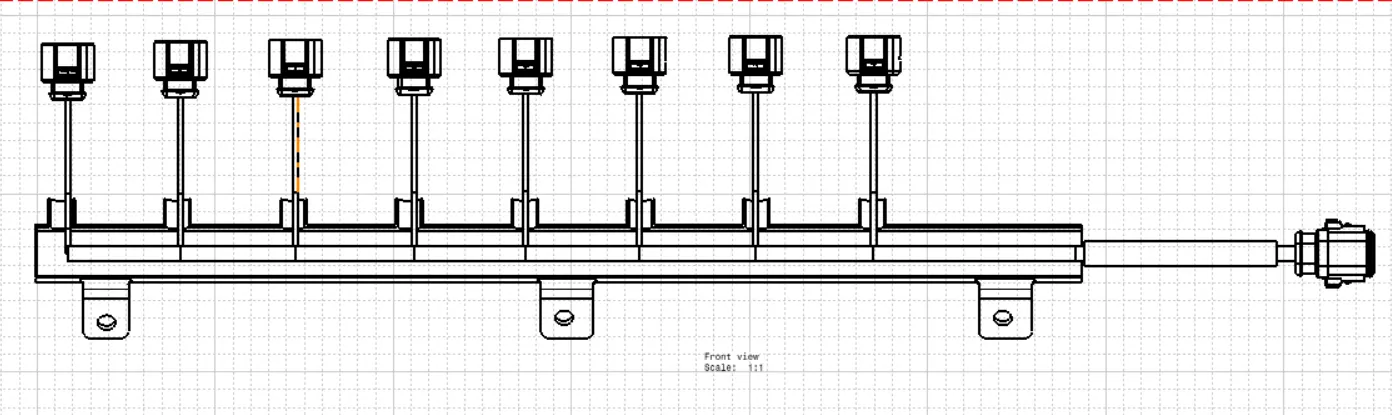
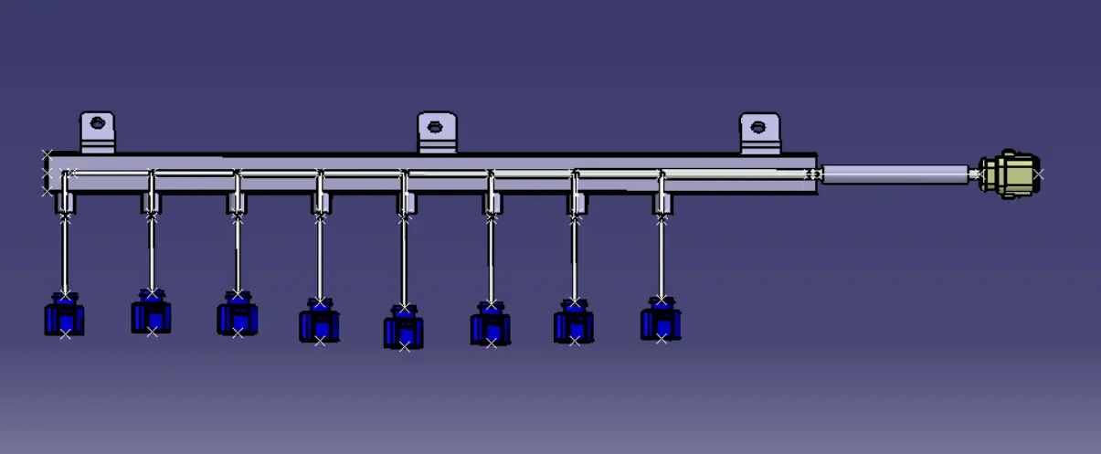
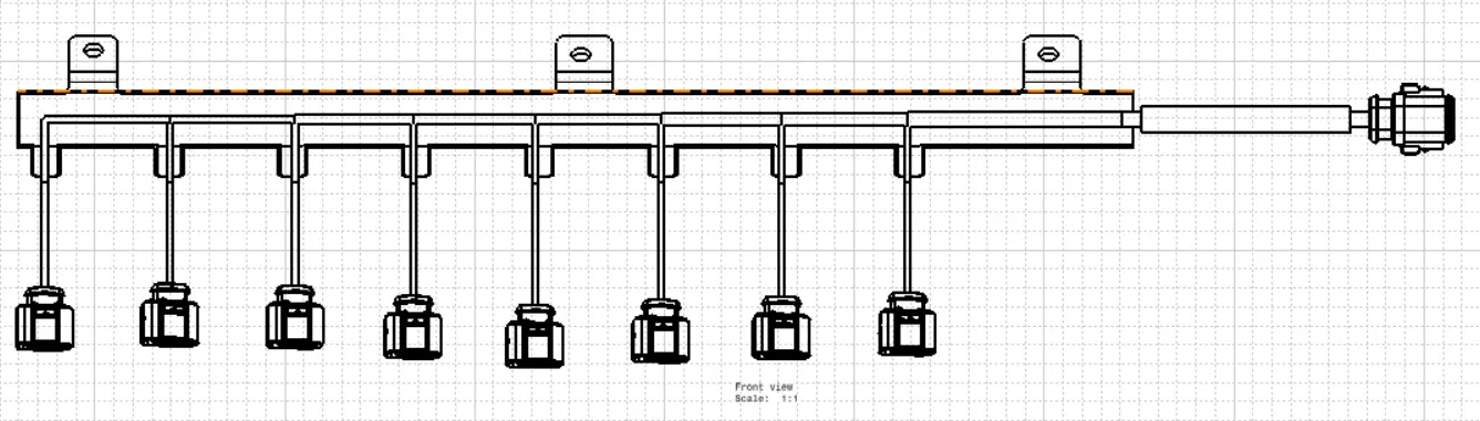
Flattening of all Harness
Engine_Harness Flattening
Engine_Channel_harness_LH
Engine_Channel_harness_RH
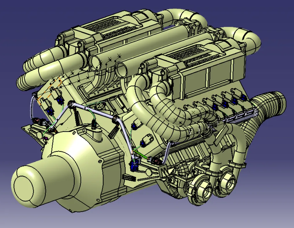
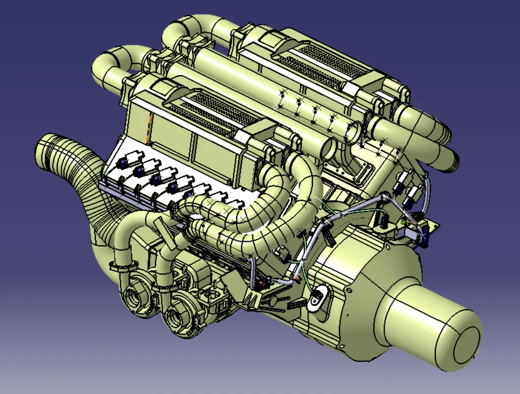
Final Harness Assembly
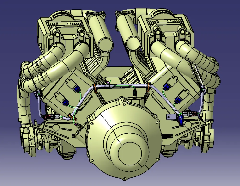
Conclusion:
Route the Wiring harness on the Given Engine CAD data and Prepare a flattened view drawing in CATIA V5 has been done.
NOTE:
I could not upload CAD data hence I enclose the the Drive link

https://drive.google.com/file/d/12dR-ybwZrOYu0FZ4X_ugcJssdiRfcktI/view?usp=sharing