Transient Structural Analysis on a Double Universal joint with a spring
Aim:
To perform a transient structural analysis on a double universal joint with a spring using three different materials
- Structural Steel
- Stainless Steel
- Titanium alloy
The three materials must be used on the joint with the springs alone.
We need to obtain the Equivalent stress and total deformation for all the three cases and compare them.
Geometry:
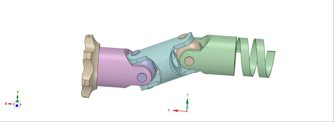
Then we have to import into ansys, import the model, and open it in space claim so that ansys will read it and checked for any errors.
Material :
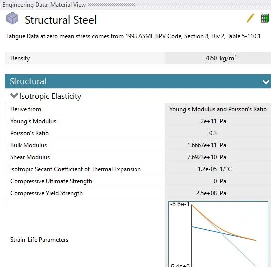
Structural steel:
Structural steel is a category of steel construction material that is produced with a particular cross-section or shape, and some specified values of strength and chemical composition. Structural steel composition, strength, size, shape, strength, and storage are controlled in most advanced countries. The word structural steel includes a broad variety of low carbon and manganese steels that are used in great numbers for civil and marine engineering applications.
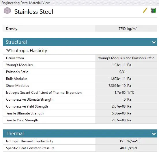
Stainless steel:
Stainless steel is a group of iron-based alloys that contain a minimum of approximately 11% chromium, a composition that prevents the iron from rusting as well as providing heat-resistant properties.
Different types of stainless steel include the elements carbon (from 0.03% to greater than 1.00%), nitrogen, aluminum, silicon, sulfur, titanium, nickel, copper, selenium, niobium, and molybdenum. Specific types of stainless steel are often designated by a three-digit number stainless.
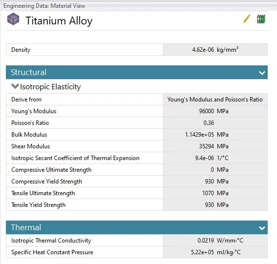
Titanium Alloy:
Titanium alloys are alloys that contain a mixture of titanium and other chemical elements. Such alloys have very high tensile strength and toughness (even at extreme temperatures). They are light in weight, have extraordinary corrosion resistance, and the ability to withstand extreme temperatures.
Meshing:
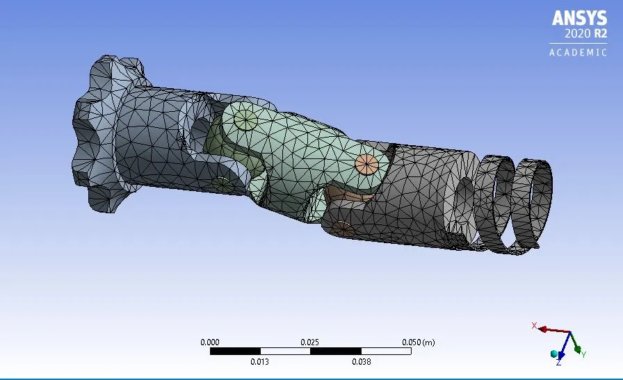
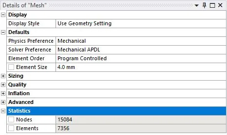
However, regions of particular interest i.e contacting surface between follower and cam are meshed using face sizing with a mesh element size of 4 mm.
The meshed model image and mesh metric graph can be seen below:
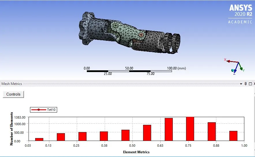
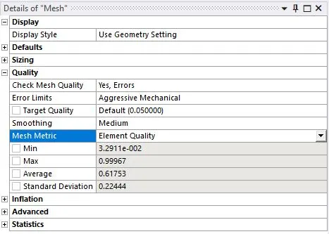
The mesh metric is utilized to identify the elements according to their quality using skewness. The quality of the mesh is acceptable as most of the elements lie within a high-quality range.
Joints:
Body to body connection types was used as per the requirement for the simulation.
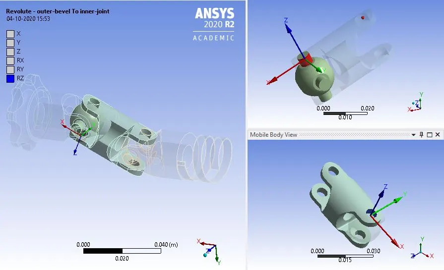
Revolute joint for outer bevel to inner joint:
In joints in order to perform rotation action, a revolute joint is applied to the outer bevel and inner joint hence able to rotate in its position and perform revolute operations.
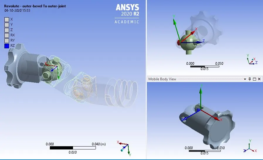
Revolute joint for outer bevel to outer joint:
In joints in order to perform rotation action, a revolute joint is applied to the outer bevel and outer joint hence able to rotate in its position and perform revolute operations.
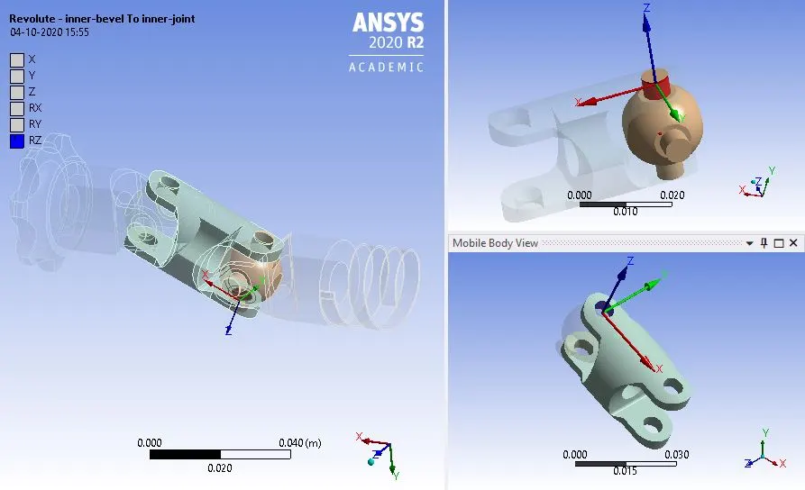
Revolute joint for Inner bevel to inner joint:
In joints in order to perform rotation action, a revolute joint is applied to the inner bevel and inner joint hence able to rotate in its position and perform revolute operations.
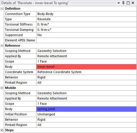
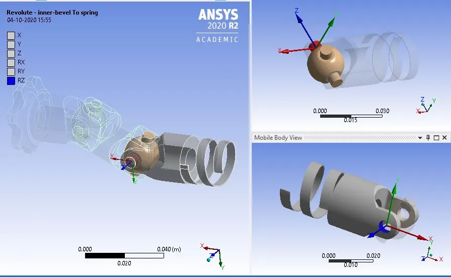
Revolute joint for inner bevel to spring joint:
In joints in order to perform rotation action, a revolute joint is applied to the inner bevel and inner joint hence able to rotate in its position and perform revolute operations.
Boundary conditions:
In boundary conditions to the holder, the rest of the assembly in place revolute support is assigned individually to the outer bevel and one end of the spring which is outside.
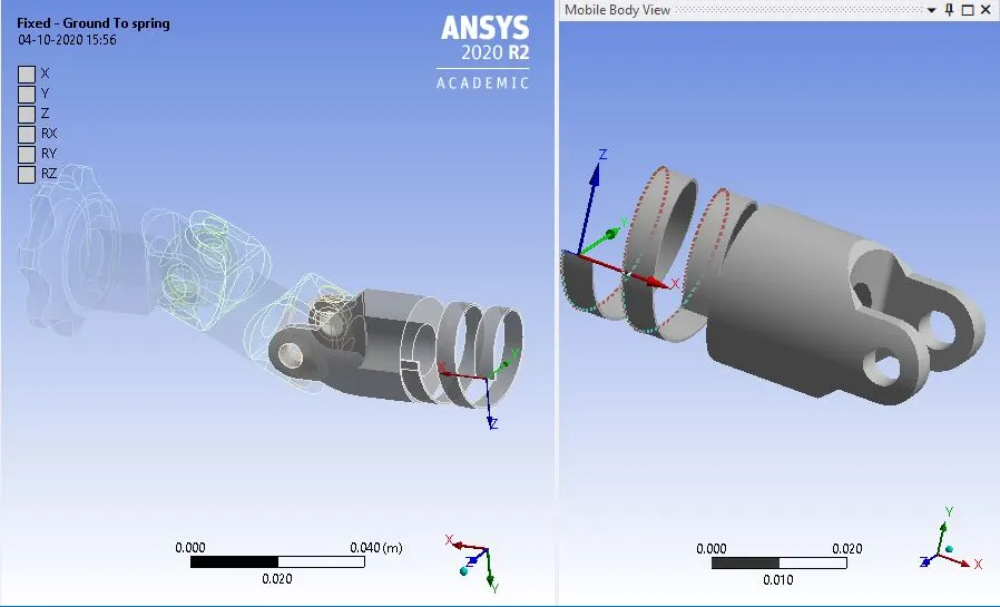
Fixed joint for the Spring side:
The fixed support joint was applied on the spring
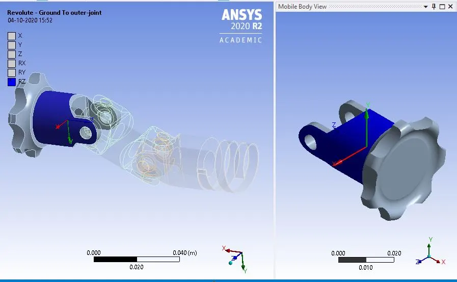
Revolute joint for the Outer joint:
The rotation joint was provided for the revolutionary movement for the outer bevel.
Rotation for the outer joint:
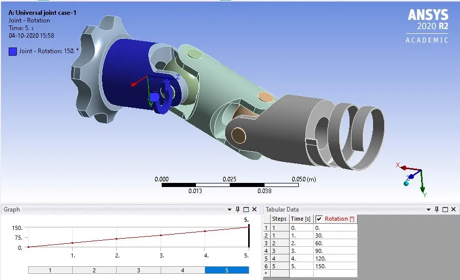
The rotation for the outer joint has been provided as shown in the picture above.
Analytical Settings:
The analysis is done in 5-time steps. In which auto time stepping is switched to program-controlled.
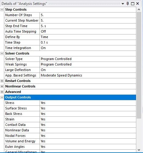
while for the rest of the steps it is switched ON and with the input of max time increment as 0.1.
Results:
Result for case-1 using Structural Steel:
Total deformation on the setup.
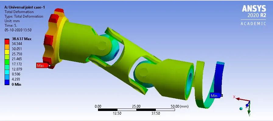
Animation for the Total deformation on the setup.
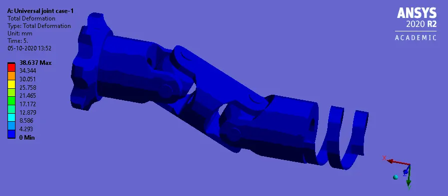
Equivalent stress on the setup.
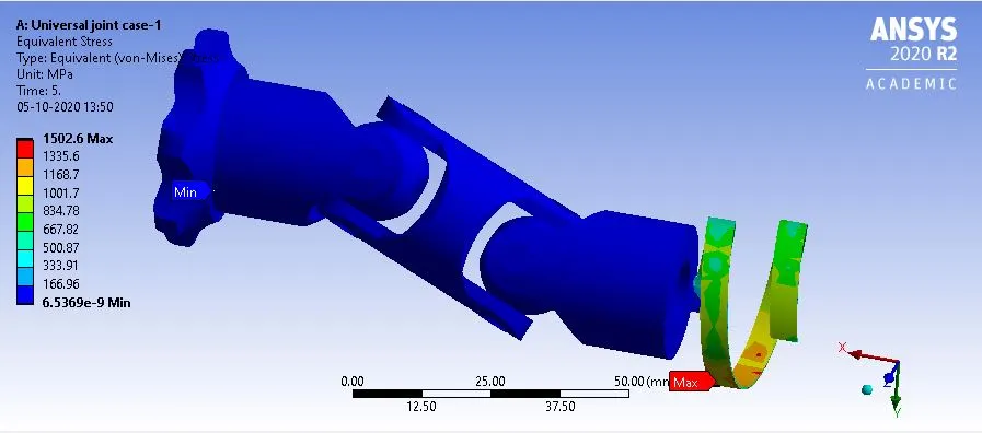
Animation for the Equivalent stress on the setup.
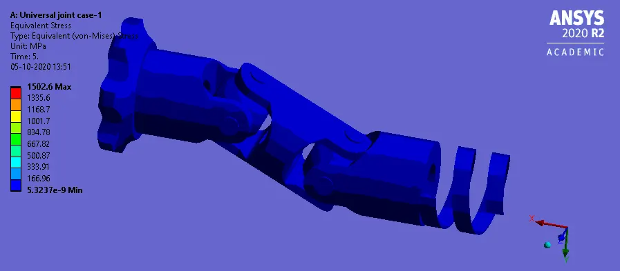
Result for case-2 using Stainless Steel:
Total deformation on the setup.
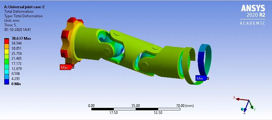
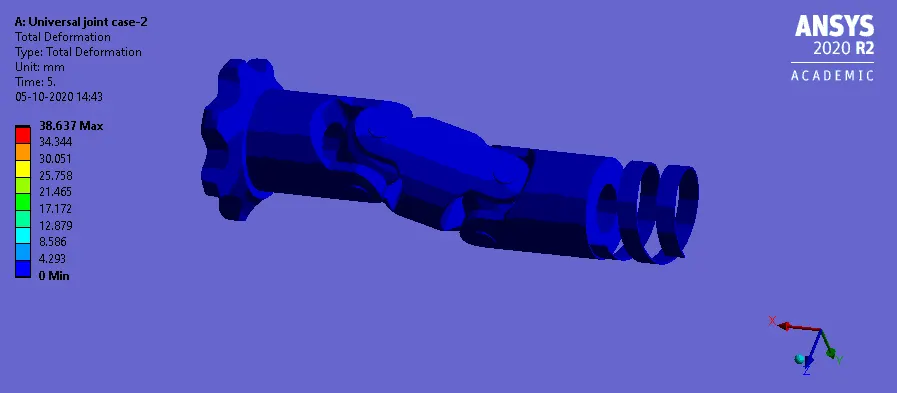
Animation for the Total deformation on the setup.
Equivalent stress on the setup.
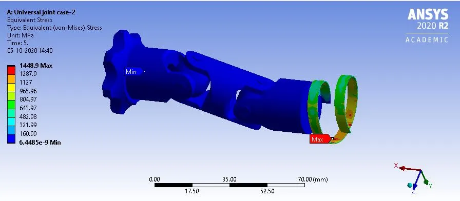
Animation for the Equivalent stress on the setup.
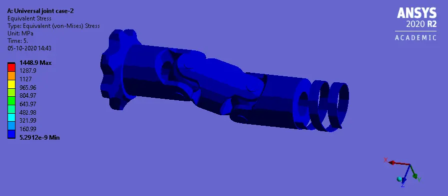
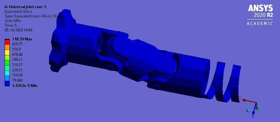
Result for case-3 using Titanium alloy:
Total deformation on the setup.
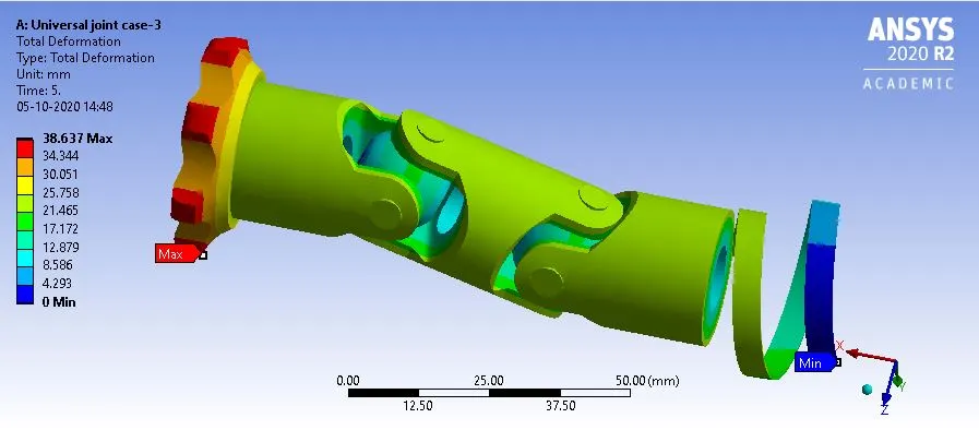
Animation for the Total deformation on the setup.
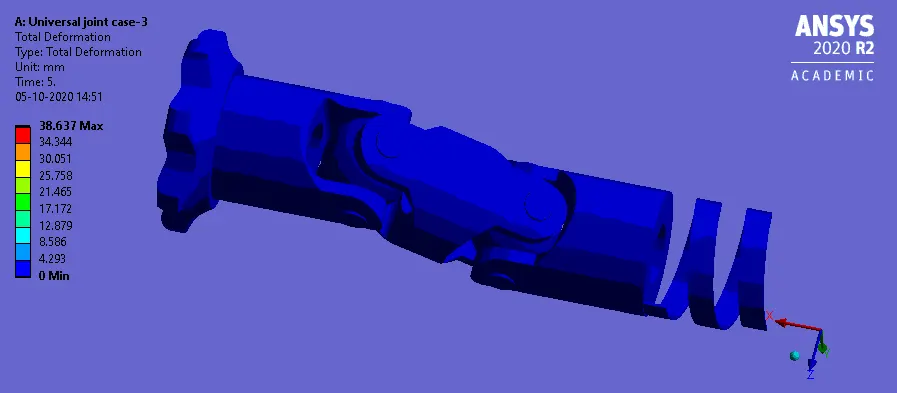
Equivalent stress on the setup.
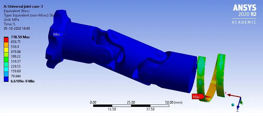
Animation for the Equivalent stress on the setup.
Conclusion:
| Title | CASE-1{Structural Steel} | CASE-2{Stainless Steel} | CASE-3{Titanium Alloy} |
| Total deformation | 38.63 | 38.63 | 38.63 |
| Equivalent stresses | 1502 | 1448 | 718 |
From the above table, we can say that the total deformation remains constant for all three materials.
But the stress for structural steel is the highest of the three. There is a slight difference in the values of stress between stainless and structural steel.
But the titanium alloy has the least stress-induced of all the three materials.
As the structural steel has the highest value of young's modulus of all three the stress is maximum and titanium has the lowest value of young's modulus of stress is lowest in titanium.