Stress Concentration on a Plate with hole
Aim:
The task, in this case, is to design a rectangular plate with a given diameter and thickness according to the challenge and to perform static structural analysis using ansys workbench. The material used is structural steel.
Determine the maximum deformation and stress developed in the model.
Case:1
Design a plate with a hole model similar to what we worked in the class, but with increased thickness.
Following are the Plate dimensions:
Length = 300mm
Height = 120mm
Thickness = 30mm
Circular Hole at the center: Diameter = 60mm
In space claim, we have created a 2D dimensional plate similar to what we worked in the class but the increased thickness.
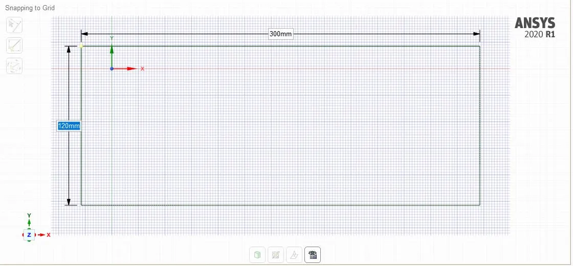
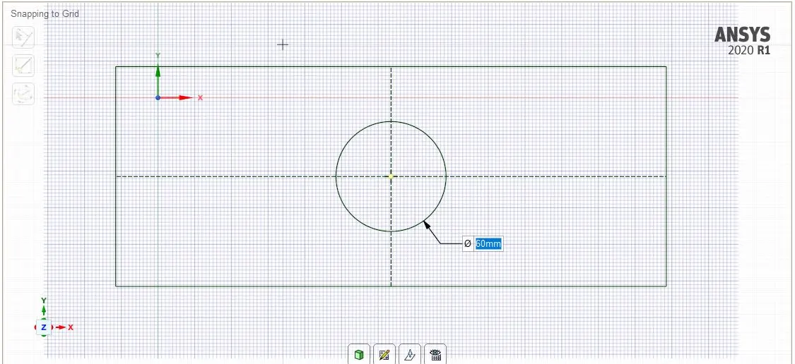
we have now created the hole for the plate with a Circular Hole at the center Diameter = 60mm
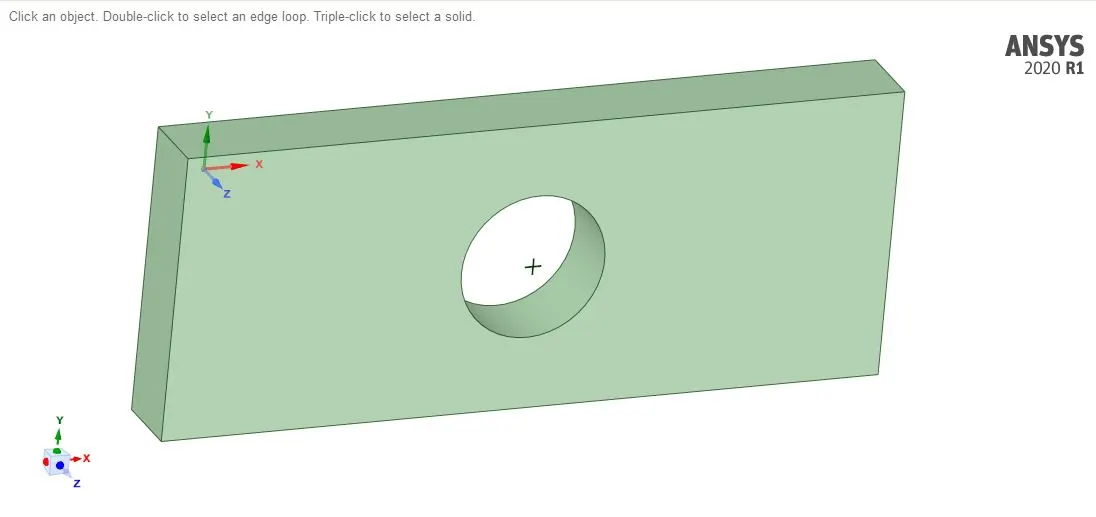
The 2D geometry sketch is then extruded in SpaceClaim as shown below and this 3D model than can be imported into Ansys Mechanical for the structural analysis.
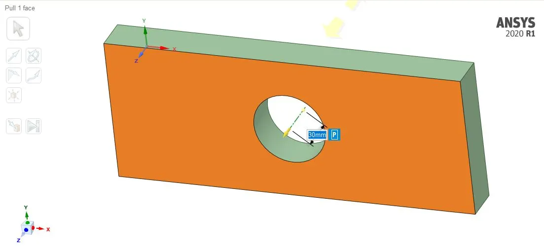
A thickness of 30 mm have been provided for the plate that has been provided in the challenge
Material:
The properties of the Structural Steel Material are as a following:
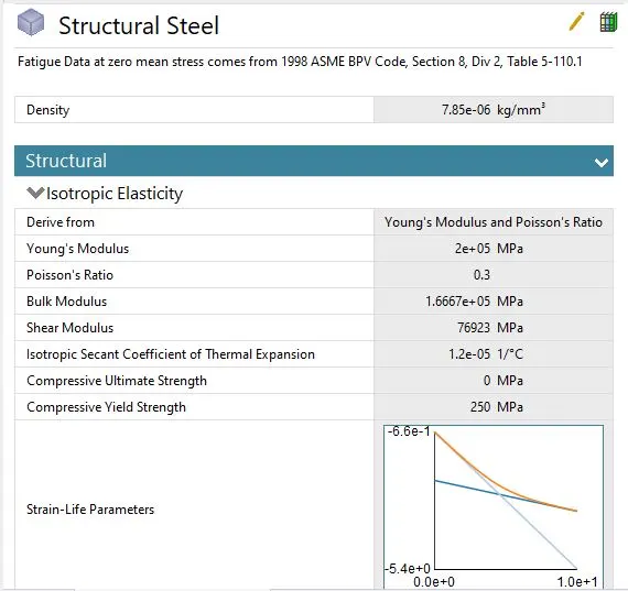
The assigned material is structural steel.
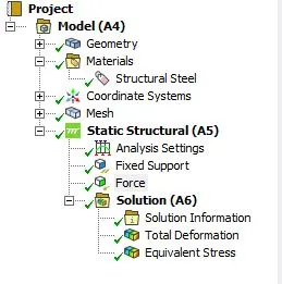
The next step is to mesh the model. Since the required material is structural steel the default material has not been changed.
Mesh :
The patch conforming method with tetrahedrons is utilized for the mesh and no other default settings have been changed. the meshed model for the plate is as follow
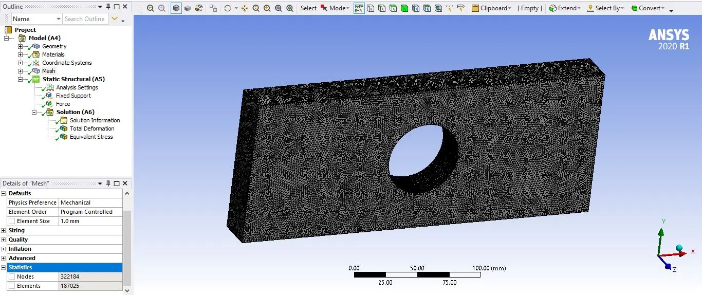
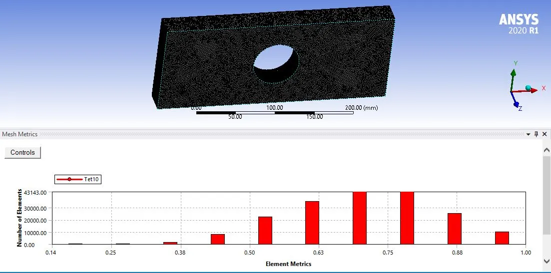
The appropriate element size was finalized by iteration 1mm element size was finalized as it does not exceed the allowable nodes and elements. The mesh metric is utilized to identify the elements according to their quality. The quality of the mesh is acceptable as most of the elements lie within a high-quality range of 0.6-0.9
Boundary conditions:
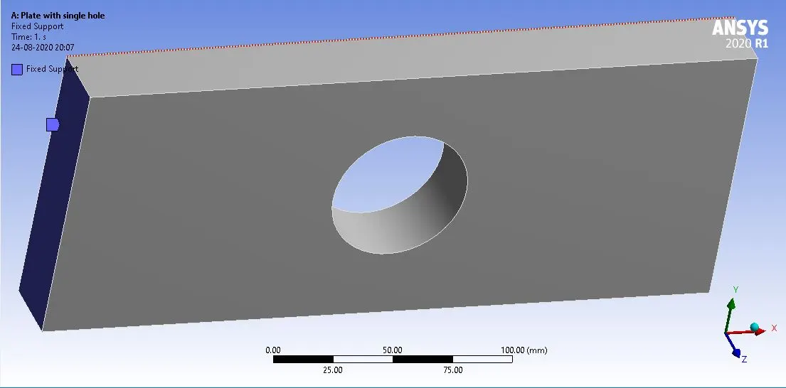
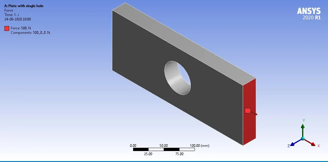
Now for the boundary conditions, a fixed supported on side of the plate is applied and a tensile load of 500N is applied on the opposite side as shown in the picture below
Fixed end:
Tensile load on the Right-hand side:
Case-1
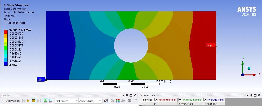
The Total deformation :
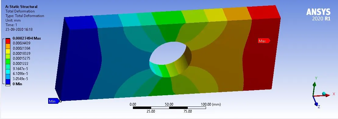
Maximum and Minimum deformation on the plate:
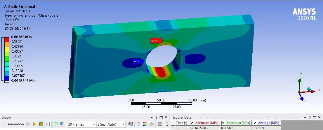
Maximum and Minimum Equivalent Von-Mises stress on the plate:
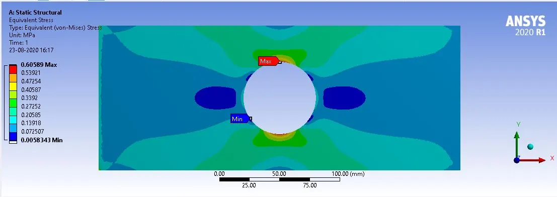
Equivalent Von-Mises stress:
Case:2
smaller holes 90mm away from the center:
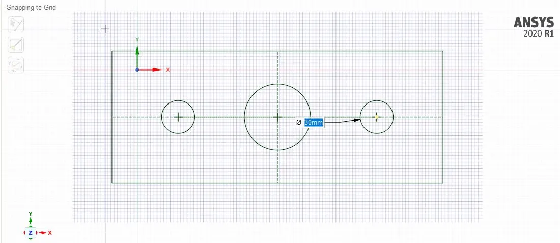
Diameter=30mm
Boundary Conditions:
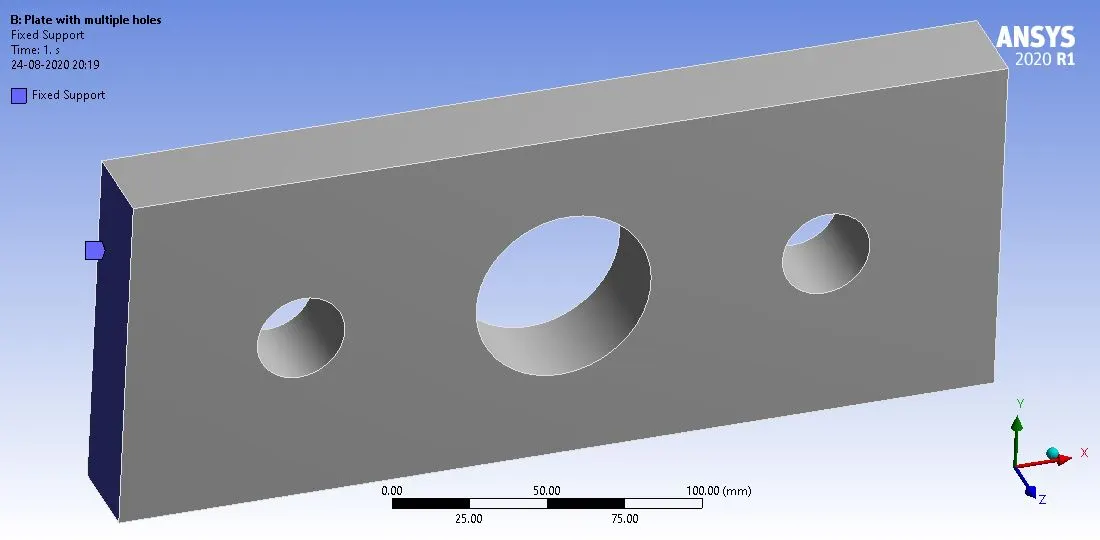
Plate fixed on the left face.
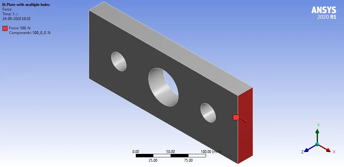
Load of 500N on the right face.
In space claim, we have created a 2D dimensional plate similar to what we worked in the class but the increased thickness.
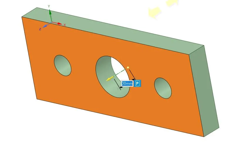
we have now created the hole for the plate with a Circular Hole at the center Diameter 60mm and with a dimension of 90mm on either from the center of the geometry.
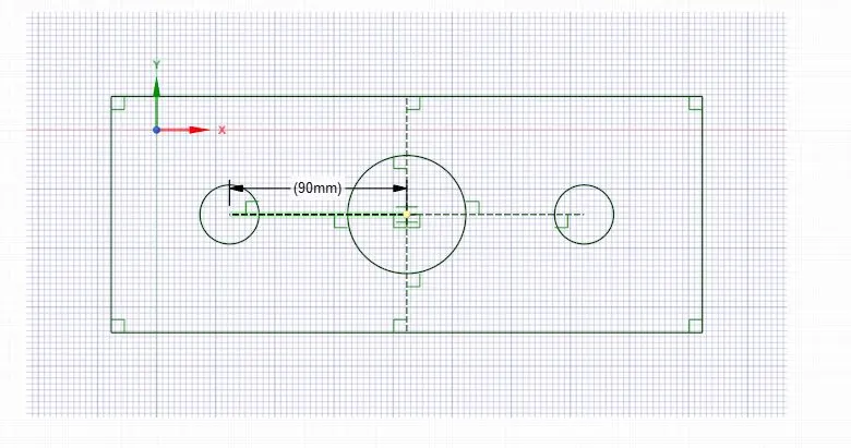
we have now created the two-hole for the plate with a Circular Hole at the center Diameter 30mm
The 2D geometry sketch is then extruded in SpaceClaim as shown below and this 3D model than can be imported into Ansys Mechanical for the structural analysis.
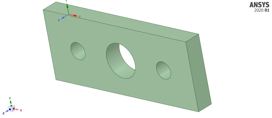
A thickness of 30 mm have been provided for the plate that has been provided in the challenge
Material:
The properties of the Structural Steel Material are as a following:
The assigned material is structural steel.
The next step is to mesh the model. Since the required material is structural steel the default material has not been changed.
Mesh :
The patch conforming method with tetrahedrons is utilized for the mesh and no other default settings have been changed. the meshed model for the plate is as follow
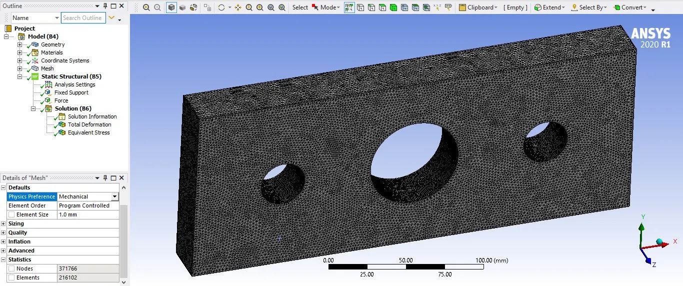
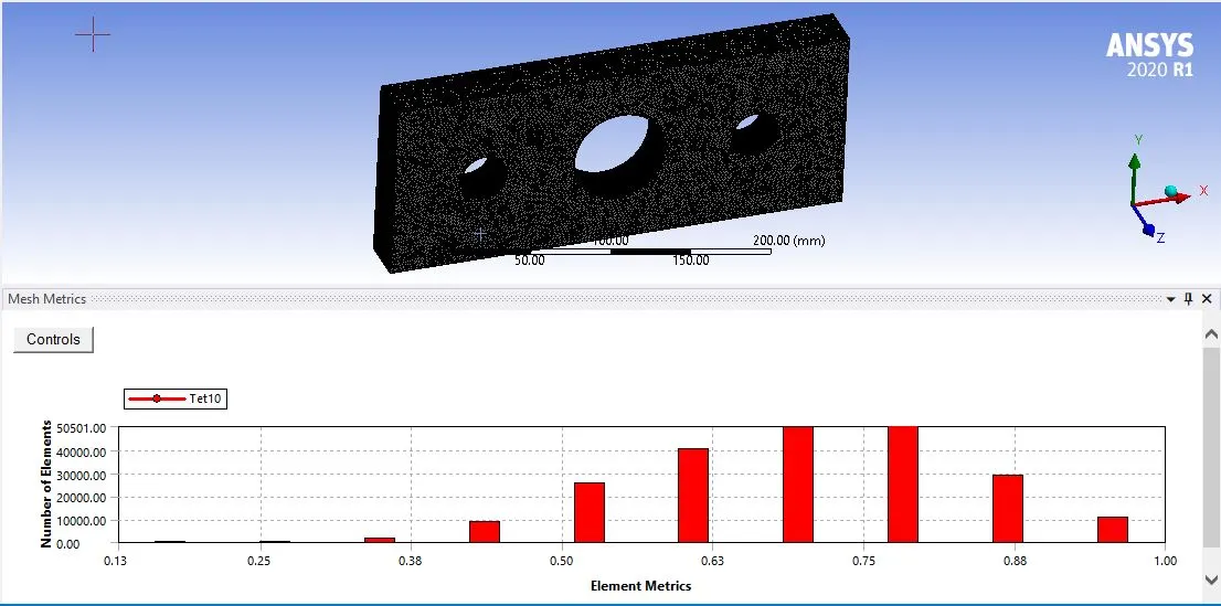
The appropriate element size was finalized by iteration 1mm element size was finalized as it does not exceed the allowable nodes and elements. The mesh metric is utilized to identify the elements according to their quality. The quality of the mesh is acceptable as most of the elements lie within a high-quality range of 0.6-0.9
Boundary conditions:
Now for the boundary conditions, a fixed supported on side of the plate is applied and a tensile load of 500N is applied on the opposite side as shown in the picture below
Fixed end:
Tensile load on the Right-hand side:
Case-2
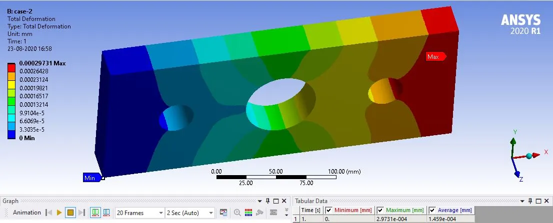
The Total deformation :
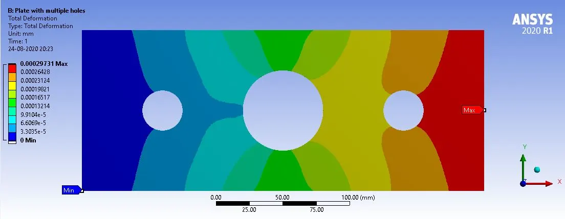
Maximum and Minimum deformation on the plate:
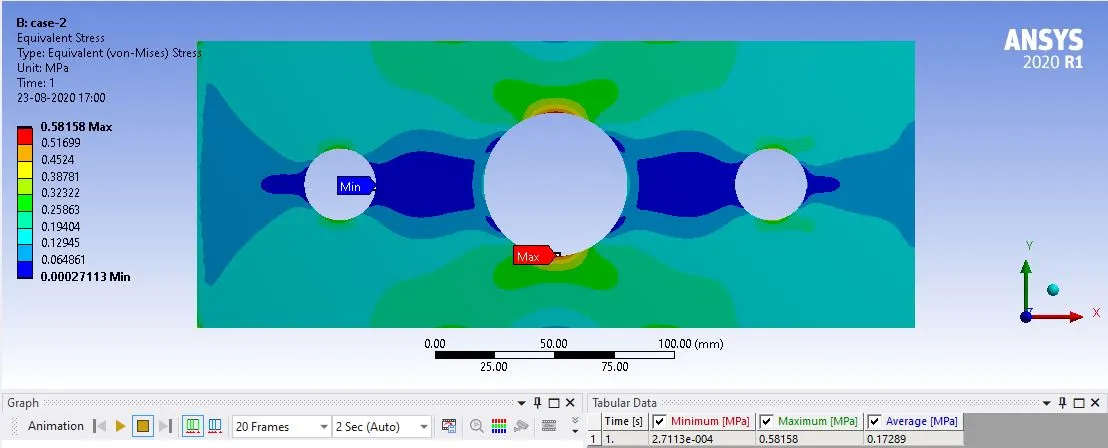
Equivalent Von-Mises stress on the plate:
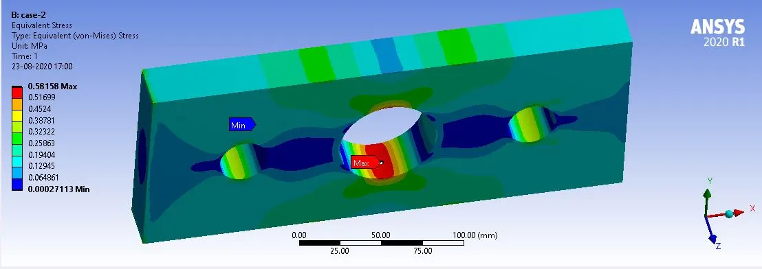
Maximum and Minimum Equivalent Von-Mises stress on the plate:
Result:
After solving the models the following results are obtained
The Total deformation results for the cases
| Total Deformation | Case-1 | Case-2 |
| Min Deformation (mm) | 0 | 0 |
| Max Deformation (mm) | 2.74e-004 | 2.97e-004 |
| Avg.Deformation (mm) | 1.37e-004 | 1.45e-004 |
The Equivalent Von-Mises stress on the plate:
| Equivalent Von-Mises stress | Case-1 | Case-2 |
| Min Equivalent stress (Mpa) | 5.834e-003 | 2.7113e-004 |
| Max Equivalent stress (Mpa) | 0.605 | 0.581 |
| Avg. Equivalent stress (Mpa) | 0.1750 | 0.1728 |
Discussion :
Without any errors, the simulation was running successfully. As discussed earlier, the size of the finer elements should be used for the case as it had two additional holes and thus reduced space.
- Comparing the overall deformation for both cases with just the Standard there is just a small difference in the values. Value is clear if case-2 has higher values and the average deformation for case-2 is just 0.08 mm higher.
- The reason case-2 has higher Deformation of the case-1 because of the material reduction in case-2 decreased the stiffness and strength of the plate.
- When comparing the Equivalent stress results in a sudden geometry shift that creates a stress concentration around the holes.
- case-2 has lower Max stress as compared to case-1 because the extra 2 holes in case-2 evenly spread the stress and stress concentration.
- The stress concentration can be further reduced with the use of sufficient holes. Case-1 has 0.605 Mpa of maximum stress around the opening.
- It is also found that case-1 has higher stress than case-2 because the stress concentration is distributed in case-2 because of the holes.
From an analysis standpoint:
- The case 2 design had to be used as it decreases the concentration of stress around a single hole.
- The case-2 design will have a longer operational life and Case-1 design may fail early due to stress concentration.
From a manufacturing standpoint:
The case-1 design shall be used as a less costly process which will also avoid waste of materials and related costs. Again, there is no major difference between the two designs.
Conclusion:
Plate 2 design would be supported from the production point of view accordingly. If there is no cost restriction we can go to Plate-2 manufacturing. But as there is just a small decrease in stress we can also go plan for plate 1 as well. And it depends on what we want from the analysis and manufacturing standpoint.