Bevel Gear Grid dependency test
Aim:
The main objective of this challenge is to perform the grid independency test on the Bevel gear with different types of mesh sizes that have been provided in the challenge.
| S.NO | Mesh size | Units |
| 1 | 6 | mm |
| 2 | 4 | mm |
| 3 | 5 | mm |
Grid dependency test:
The convergence of grid dependence is the terminology used to characterize results improvement by successively using smaller mesh sizes.
The best decision should be drawn to a calculation when the grid convergence becomes finer. With the grid getting refined and the time phase completed, spatial and temporal discrete error were reduced, asymptotically zero should approach respectively, excluding the system roundoff error.
The Grid Dependency Test is used in high-stress areas to predict accurately the results. This can be accomplished by adjusting the size of the mesh in some areas before the final results are verified.
Introduction:
Bevel gears are gears where the axes of the two shafts intersect and the tooth-bearing faces of the gears themselves are conically shaped. Bevel gears are most often mounted on shafts that are 90 degrees apart but can be designed to work at other angles as well. The pitch surface of bevel gears is a cone.
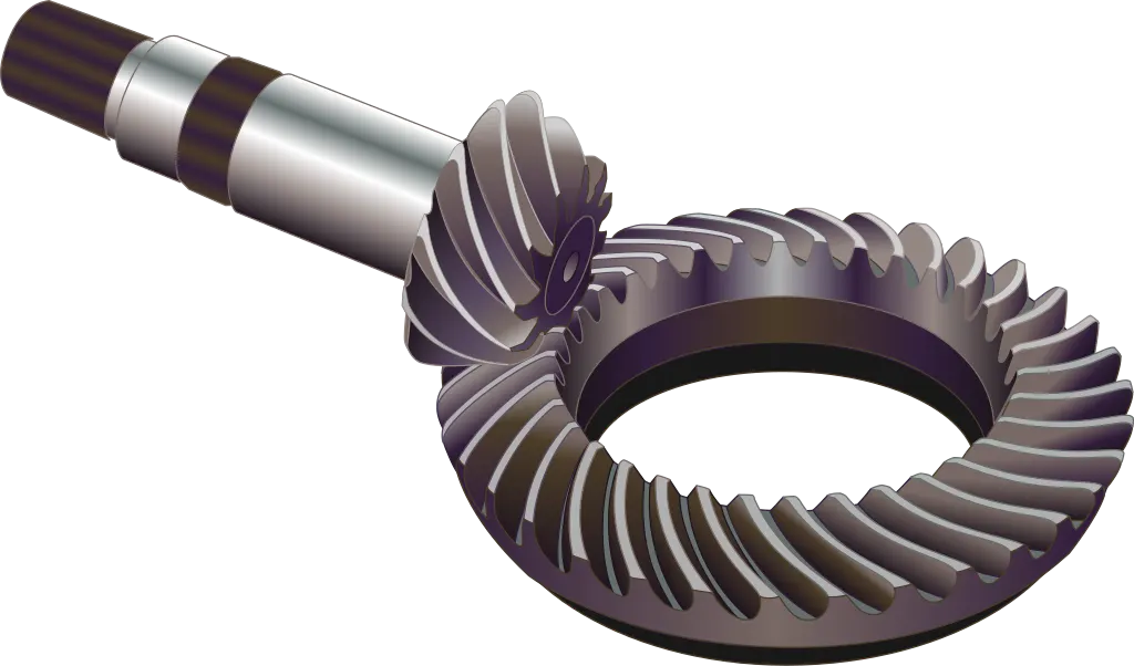
Two important concepts in gearing are pitch surface and pitch angle. The pitch surface of a gear is the imaginary toothless surface that you would have by averaging out the peaks and valleys of the individual teeth. The pitch surface of an ordinary gear is the shape of a cylinder. The pitch angle of a gear is the angle between the face of the pitch surface and the axis.
The most familiar kinds of bevel gears have pitch angles of less than 90 degrees and therefore are cone-shaped. This type of bevel gear is called external because the gear teeth point outward. The pitch surfaces of meshed external bevel gears are coaxial with the gear shafts; the apexes of the two surfaces are at the point of intersection of the shaft axes. Bevel gears that have pitch angles of greater than ninety degrees have teeth that point inward and are called internal bevel gears.
Bevel gears that have pitch angles of exactly 90 degrees have teeth that point outward parallel with the axis and resemble the points on a crown. That's why this type of bevel gear is called a crown gear.
Types:
Bevel gears are classified in different types according to geometry:
- Straight bevel gears have a conical pitch surface and teeth are straight and tapering towards the apex.
- Spiral bevel gears have curved teeth at an angle allowing tooth contact to be gradual and smooth.
- Zerol bevel gears are very similar to a bevel gear, but the teeth are curved: the ends of each tooth are coplanar with the axis, but the middle of each tooth is swept circumferentially around the gear. Zerol bevel gears can be thought of as spiral bevel gears, which also have curved teeth, but with a spiral angle of zero, so the ends of the teeth align with the axis.
- Hypoid bevel gears are similar to spiral bevel, but the pitch surfaces are hyperbolic and not conical. The pinion can be offset above or below the gear center, thus allowing larger pinion diameter, longer life, and smoother mesh. If the beveled surface is made parallel with the axis of rotation, this configuration resembles a worm drive. Hypoid gears were widely used in the automobile rear axle.
Geometry:
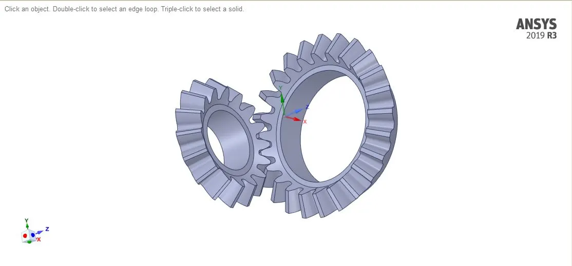
The geometry has been provided in the challenge we have imported the geometry into the space claim and made the required changes for the simulation process.
Material:
Structural steel is a category of steel construction material that is produced with a particular cross-section or shape, and some specified values of strength and chemical composition. Structural steel composition, strength, size, shape, strength, and storage are controlled in most advanced countries. The word structural steel includes a broad variety of low carbon and manganese steels that are used in great numbers for civil and marine engineering applications.
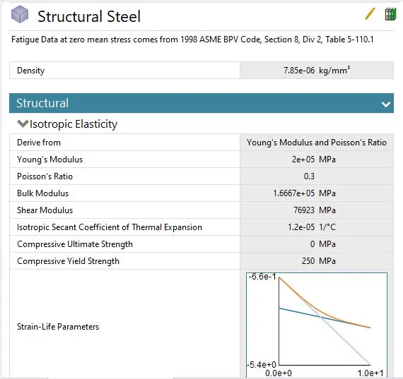
Numerous structural steels also include minor quantities of significant additions of other elements like Nb, V, Ti, and Al. These are called High Strength Low Alloy or micro-alloyed steels. Structural steels are manufactured in section and plate shapes and are normally used in bridges, buildings, ships, and pipelines.
Connections:
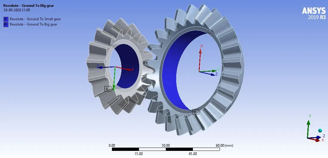
A Frictional contact is defined between the tooth faces of the teeth in contact for both the gears with the behavior being set the symmetric and "Augmented Lagrange" being used to reduce the chatter and the interface treatment being set to "Adjust to Touch"
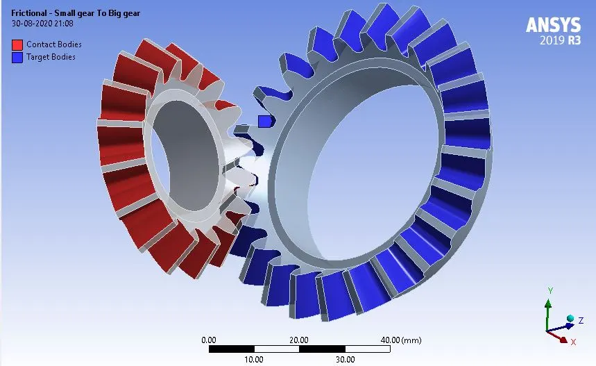
Revolute joints have been used for both gear as shown in the image below
Meshing:
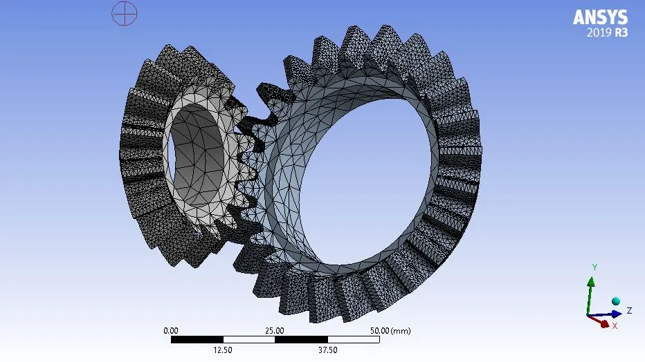
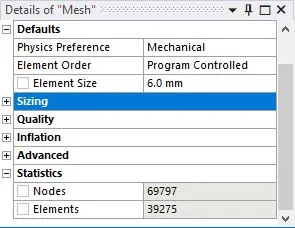
The appropriate element size was finalized by iteration 6 mm element size and a face mesh is used with 1.75 mm refinement on the teeth of the gear was finalized and the total no of nodes and elements are shown below.
The meshed model image and mesh metric graph can be seen below:
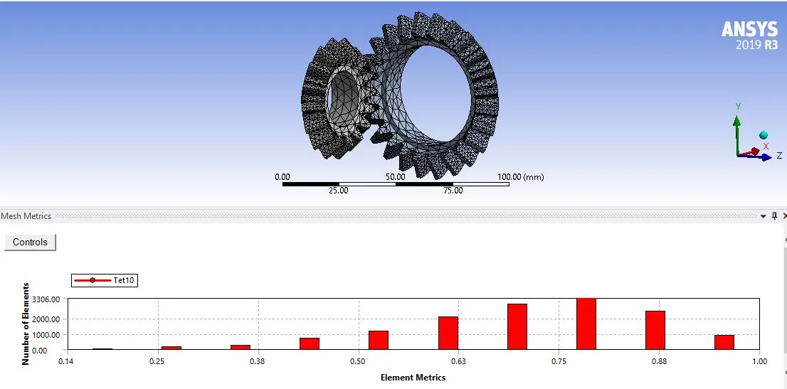
The mesh metric is utilized to identify the elements according to their quality. The quality of the mesh is acceptable as most of the elements lie within a high-quality range of 0.6-0.8.
Analytical settings:
To achieve static equilibrium and carry out static simulation at each time instant the configuration fo the gears id defined at the end and beginning of each step. Both the gears are jointed to the ground body with the help of revolute bodies for rotation about their own axis.
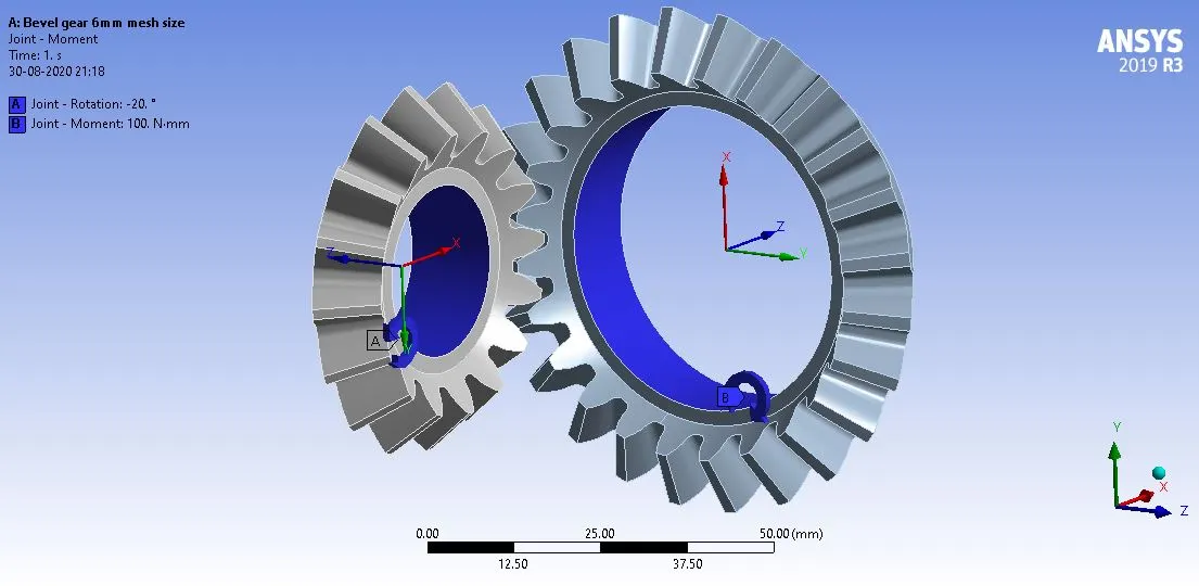
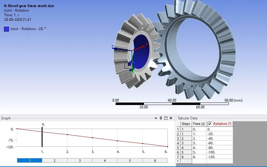
The rotation of each spur gear is divided into 6 steps with such a length of 1 second each and all steps are divided into time steps in which the solver performs a static stimulation and provides us the exact results.
The simulation runs at the end of each step and for each step the initial time step is 0.2 seconds, meaning that we also get results at (0.2,1.2,2.2,3.2,4.2)seconds. The time steps within the steps range from 0.05 seconds to 0.5 seconds
The small gear is held as the driven gear with its rotational motion, and at the beginning and end of each phase, the driving right gear is defined.
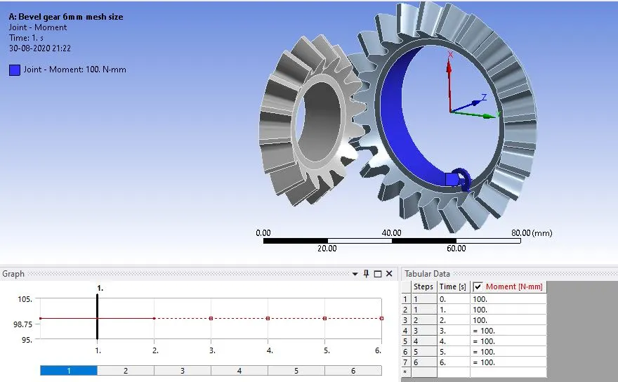
The right gear is maintained as the drive gear which induces a constant torque into its revolute joint. Since the torque at each stage is constant, the momentary joint load value of 100N-mm is stated.
Results:
For each of the necessary outputs, the minimum, average and maximum values are determined at each time step and, in contrast, only the maximum output values are considered for simplicity
Mesh sizes for the geometry for the three cases:
Case-1:
Base mesh is 6mm and face mesh is 1.75 mm
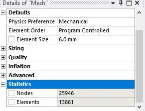
The appropriate element size was finalized by iteration 6 mm element size and a face mesh is used with 1.75 mm refinement on the teeth of the gear was finalized and the total no of nodes and elements are shown below.
The mesh metric is utilized to identify the elements according to their quality. The quality of the mesh is acceptable as most of the elements lie within a high-quality range of 0.6-0.8.
Total deformation:
The total deformation gives the outputs for all directions for each node in the mesh generation data.
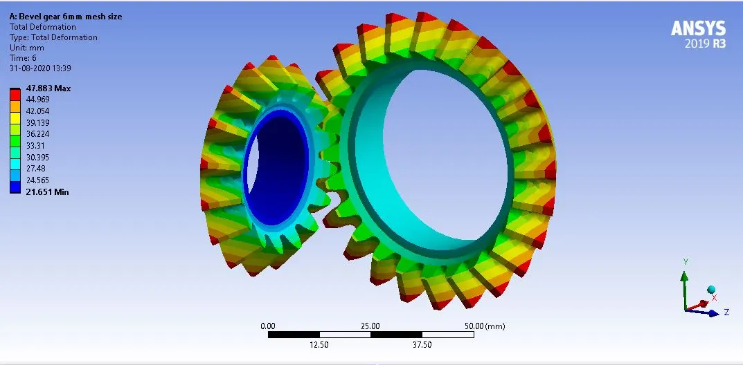
Max and Min values for the Total deformation:
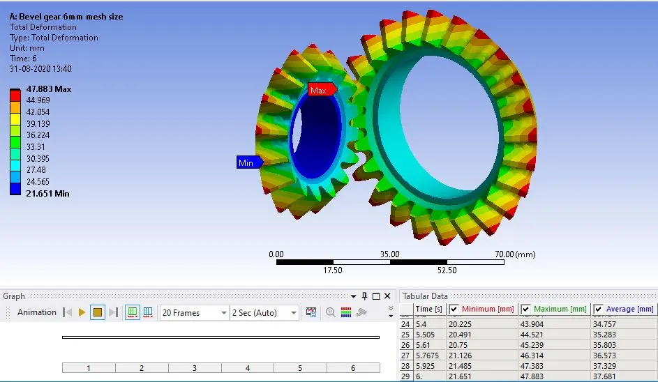
The max total deformation values are shown above in the figure.
Animation for the total deformation for the case-1:
Equivalent Stress:
As the name suggests, the equivalent non-directional stress values produced in the material of the gear were. More simply it is the energy of distortion/Shear strain in the gear.

Max and Min values for Equivalent Stress:
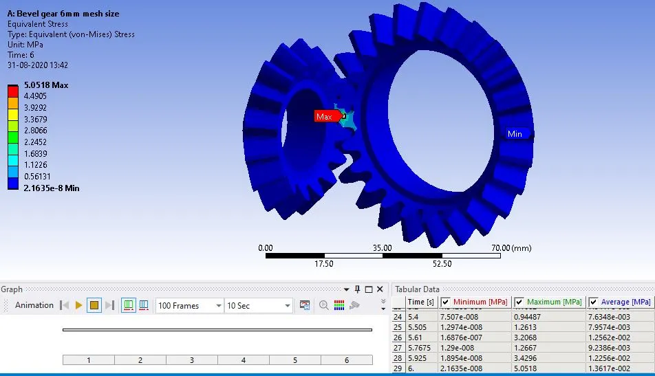
The max Equivalent Stress values are shown above in the figure.
Animation for the Equivalent Stress for the case-1:
Equivalent elastic Strain:
A scalar quantity called the equivalent strain, or the von Mises equivalent strain, is often used to describe the state of strain in solids. A form of strain in which the distorted body returns to its original shape and size when the deforming force is removed.
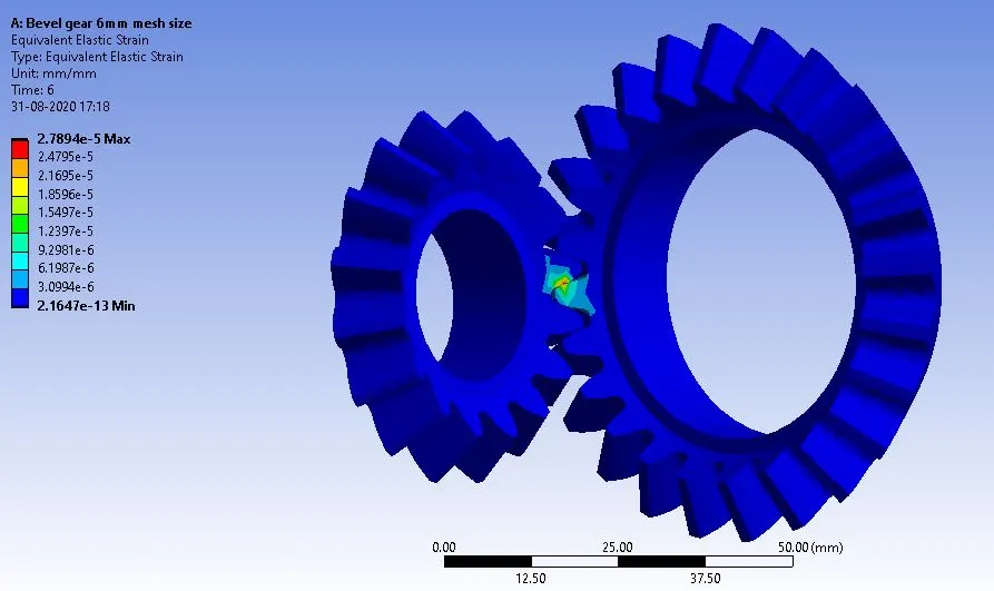
Max and Min values for Equivalent elastic Strain:
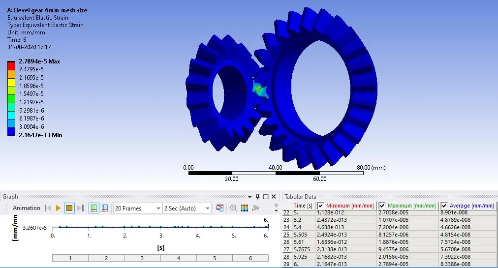
The max Equivalent elastic Strain values are shown above in the figure.
Animation for the Equivalent elastic Strain for the case-1:
Case-2:
Base mesh is 5mm and face mesh is 1.75 mm
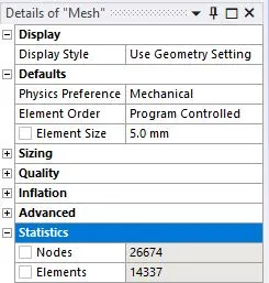
The appropriate element size was finalized by iteration 5 mm element size and a face mesh is used with 1.75 mm refinement on the teeth of the gear was finalized and the total no of nodes and elements are shown below.
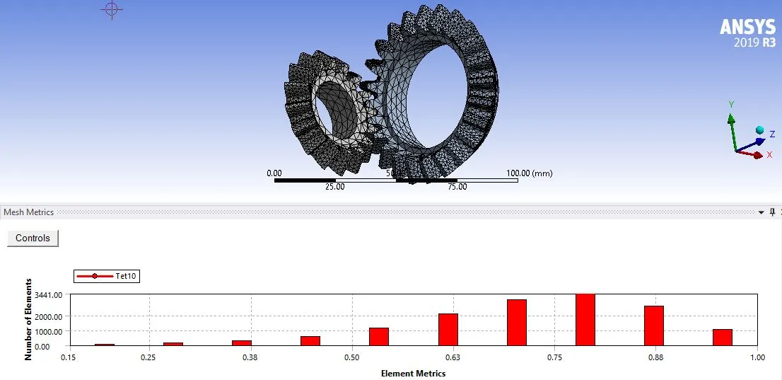
The mesh metric is utilized to identify the elements according to their quality. The quality of the mesh is acceptable as most of the elements lie within a high-quality range of 0.65-0.8.
Total deformation:
The total deformation gives the outputs for all directions for each node in the mesh generation data.
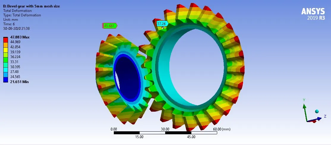
Max and Min values for the Total deformation:
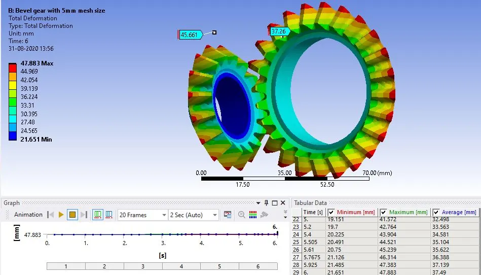
The max total deformation values are shown above in the figure.
Animation for the total deformation for the case-2:
Equivalent Stress:
As the name suggests, the equivalent non-directional stress values produced in the material of the gear were. More simply it is the energy of distortion/Shear strain in the gear.
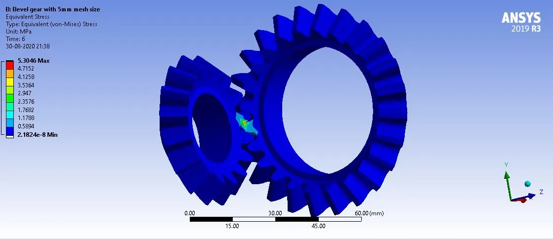
Max and Min values for Equivalent Stress:
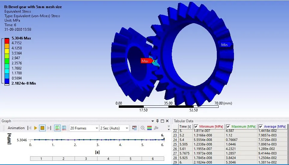
Animation for the Equivalent Stress for the case-2:
Equivalent elastic Strain:
A scalar quantity called the equivalent strain, or the von Mises equivalent strain, is often used to describe the state of strain in solids. A form of strain in which the distorted body returns to its original shape and size when the deforming force is removed.
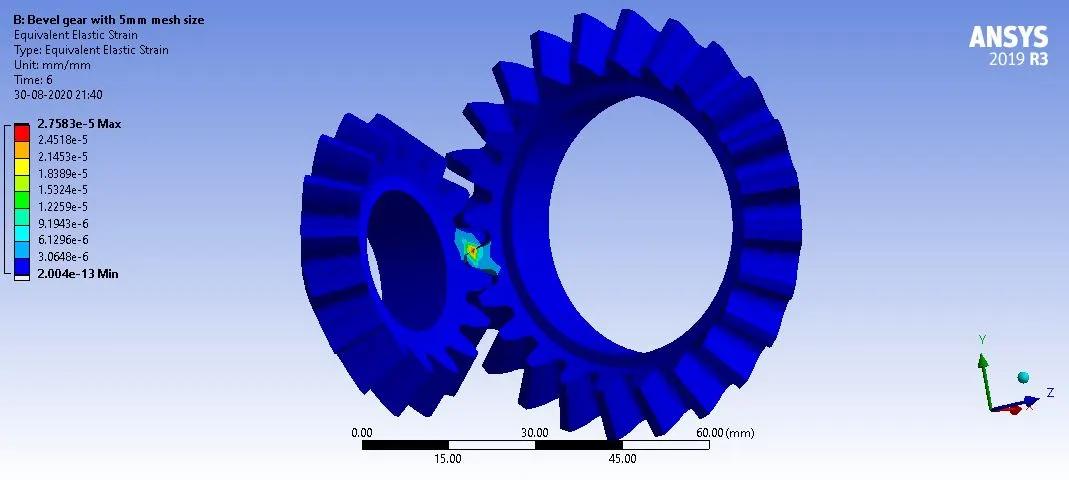
Max and Min Values of Equivalent elastic Strain:
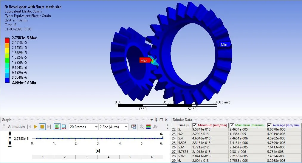
The max Equivalent elastic Strain values are shown above in the figure.
Animation for the Equivalent elastic Strain for the case-2
Case-3:
Base mesh is 4mm and face mesh is 1.75 mm
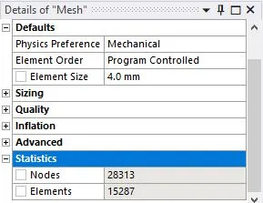
The appropriate element size was finalized by iteration 4 mm element size and a face mesh is used with 1.75 mm refinement on the teeth of the gear was finalized and the total no of nodes and elements are shown below.
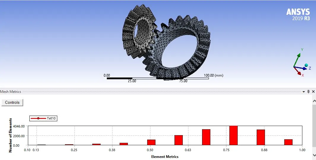
The mesh metric is utilized to identify the elements according to their quality. The quality of the mesh is acceptable as most of the elements lie within a high-quality range of 0.68-0.8.
Total deformation:
The total deformation gives the outputs for all directions for each node in the mesh generation data.
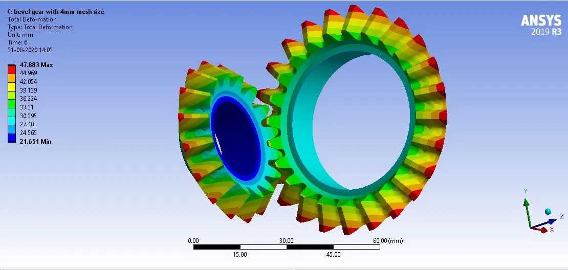
Max and Min values for the Total deformation:
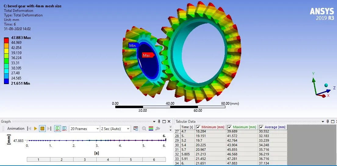
The max total deformation values are shown above in the figure.
Animation for the total deformation for the case-3:
Equivalent Stress:
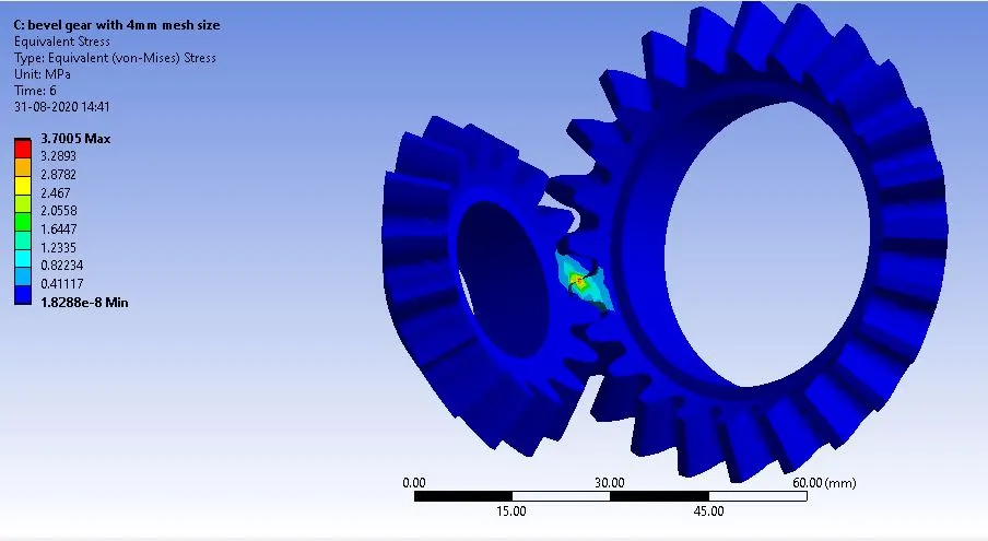
Max and Min values for Equivalent Stress:

The max Equivalent Stress values are shown above in the figure.
Animation for the Equivalent Stress for the case-3:
Equivalent elastic Strain:
A scalar quantity called the equivalent strain, or the von Mises equivalent strain, is often used to describe the state of strain in solids. A form of strain in which the distorted body returns to its original shape and size when the deforming force is removed.
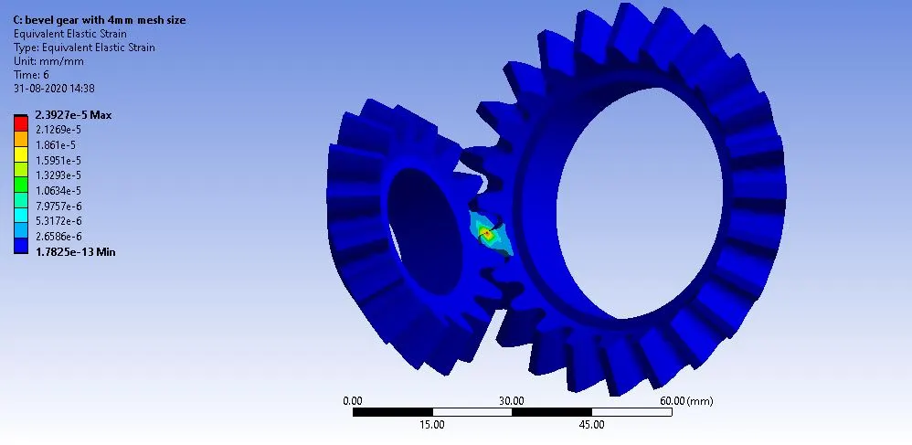
Max and Min Values of Equivalent elastic Strain:
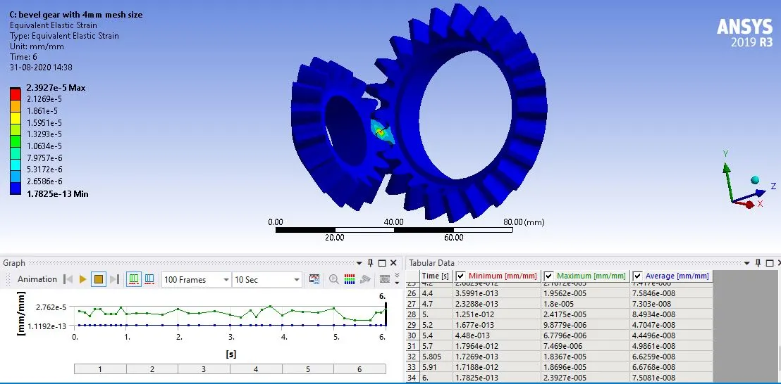
The max Equivalent elastic Strain values are shown above in the figure.
Animation for the Equivalent elastic Strain for the case-3:
Conclusion:
| Mesh size | 6mm | 5mm | 4mm |
| Total Deformation (mm) | 47.88 | 47.88 | 47.88 |
| Equivalent Stress (mm) | 5.05 | 5.30 | 3.70 |
| Equivalent elastic Strain (mm) | 2.78e-5 | 2.758e-5 | 2.3927e-5 |
When we compare the values we can see that the values continue to increase with more accurate decreases in element size. This continues until we have the most accurate value as we can see in the perceived value of deformation. This demonstrates our test regarding grid dependence.