Railwheel and Track structural analysis
AIM:
To perform a static structural analysis on the Rail Wheel and Track setup and then Multiply the bearing load by 5 times and compare the results with the load of 100000 N. Comparing the Total Deformation, Equivalent stress, and life under both the loads.
Implement a User-defined result and calculating the Total Deformation from this result and checking if it is the same as that obtained by the inbuilt result by ANSYS for a load of 100000 N.
Introduction:
A train wheel or rail wheel is a type of wheel specially designed for use on railway tracks. A rolling component is typically pushed onto an axle and mounted directly on a railway carriage or locomotive or indirectly on a bogie (in the UK), also called a truck (in North America). Wheels are cast or forged and are heat-treated to have a specific hardness. New wheels are trued, using a lathe, to a specific profile before being pressed onto an axle. All-wheel profiles must be regularly checked to ensure proper interaction between the wheel and the rail. Incorrectly trued, or worn out wheels can increase rolling resistance, reduce energy efficiency, and may even cause a derailment. A railroad wheel typically consists of two main parts: the wheel itself, and the tire around the outside. A rail tire is usually made from steel and is typically heated and pushed onto the wheel, where it remains firmly as it shrinks and cools. Monobloc wheels do not have encircling tires, while resilient rail wheels have a resilient material, such as rubber between the wheel and tire.
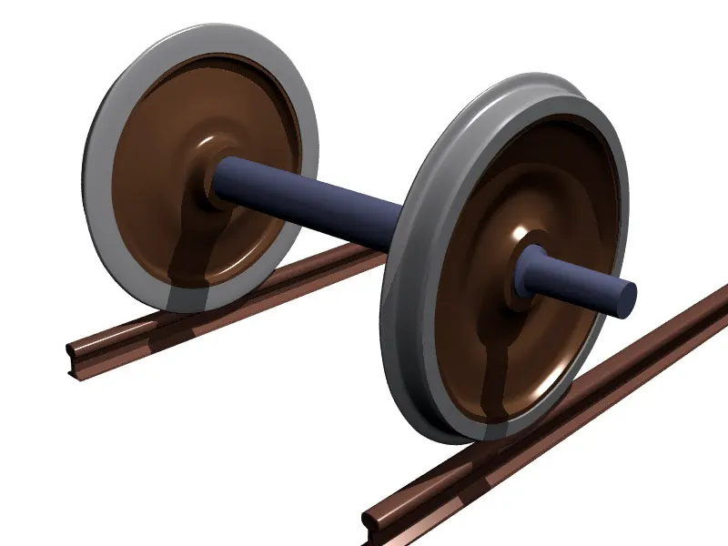
Wheel geometry and flange:
Most train wheels have a conical geometry, which is the primary means of keeping the train's motion aligned with the track. Train wheels have a flange on one side to keep the wheels, and hence the train, running on the rails when the limits of the geometry-based alignment are reached, e.g. due to some emergency or defect. See Hunting oscillation. Some wheels have a cylindrical geometry, where flanges are essential to keep the train on the rail track.
Geometry:
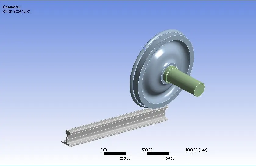
Geometry is directly imported in the workbench from the source. It consists of 3parts the are
1.Rail-wheel
2.Shaft
3.axle and track
Assembled.
Material:
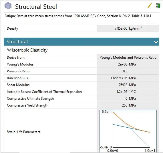
Structural steel is used as a material for each of the components in the geometry.
Meshing:
Program controlled meshing is done with a mesh element size of 35mm. Face meshing is also introduced in the region of contacts with a mesh element size of 20mm.
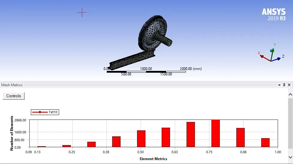
No of elements = 26270
No of Nodes = 13745
Avg Element Quality = 0.75.
Setup or Boundary Conditions:
Contacts:
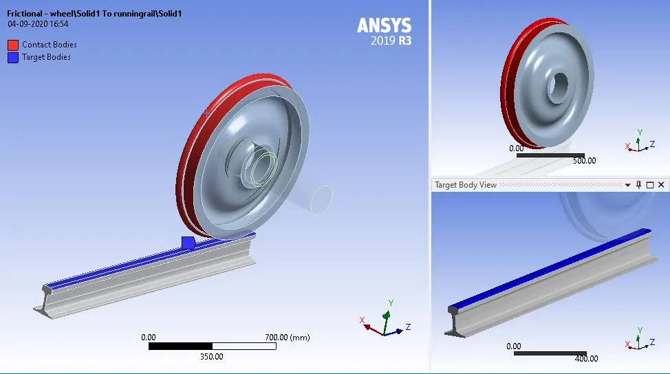
Frictional contact between wheel and Track interface
Frictional contact is established between running rail and wheel. With 0.3 as the magnitude of the frictional coefficient between interface.
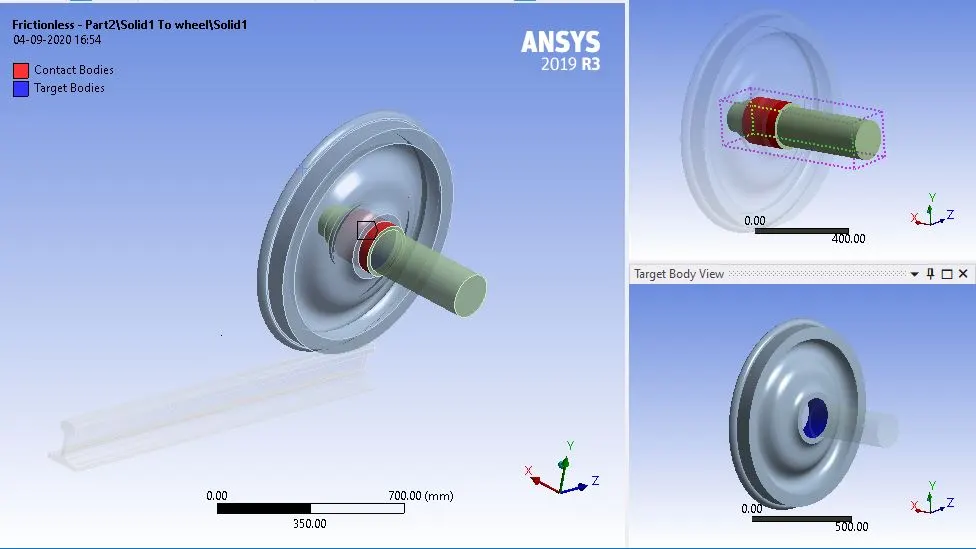
Frictionless contact between the wheel hub and shaft-axle
Frictionless contact is introduced between the shaft and wheel interface.
Joints:
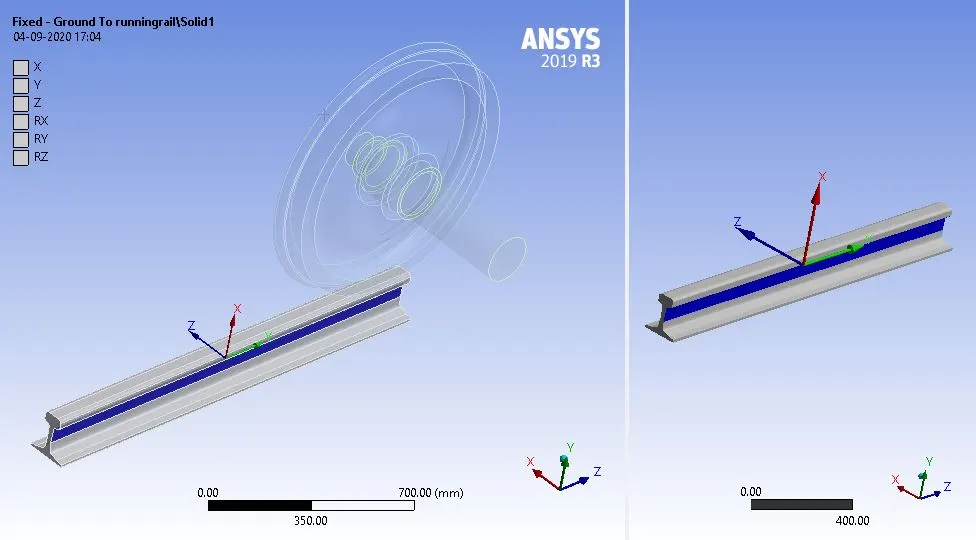
Fixed joint on the Rail track
A fixed joint is applied on running track so that it remains intact without any displacement.
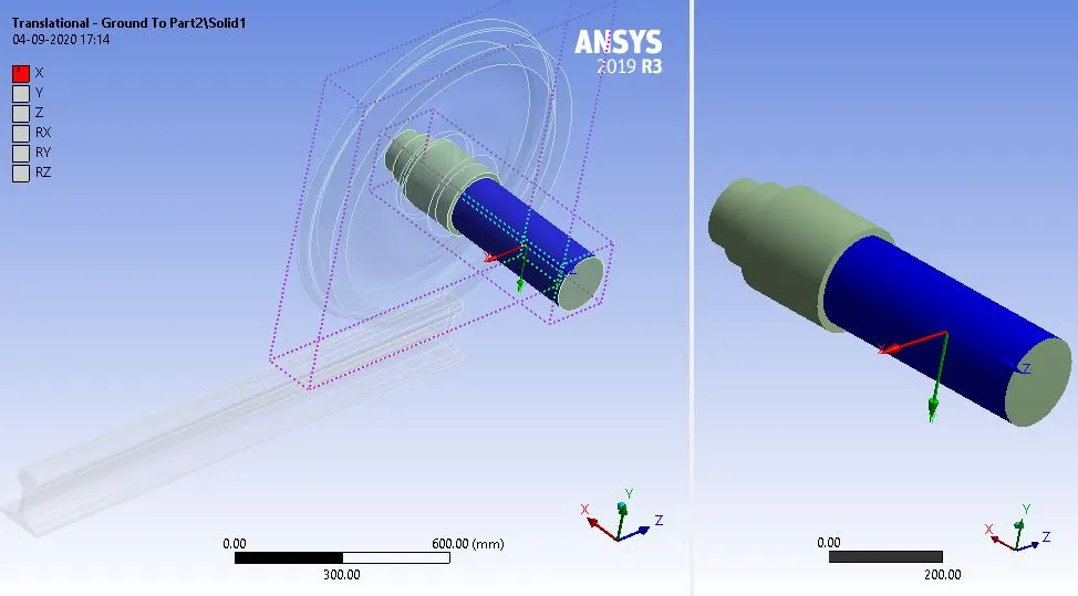
Translation joint for the shaft
The translational joint is applied to the shaft.
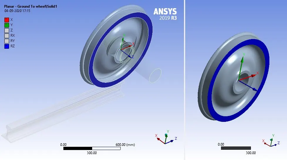
Planar joint on wheel
The panel joint is applied on the wheel hence constrained motion of the wheel to roll only.
Displacement Condition on the shaft:
The displacement boundary condition is applied on the shaft which has a translational joint imposed on it to allow movement in one axis direction.
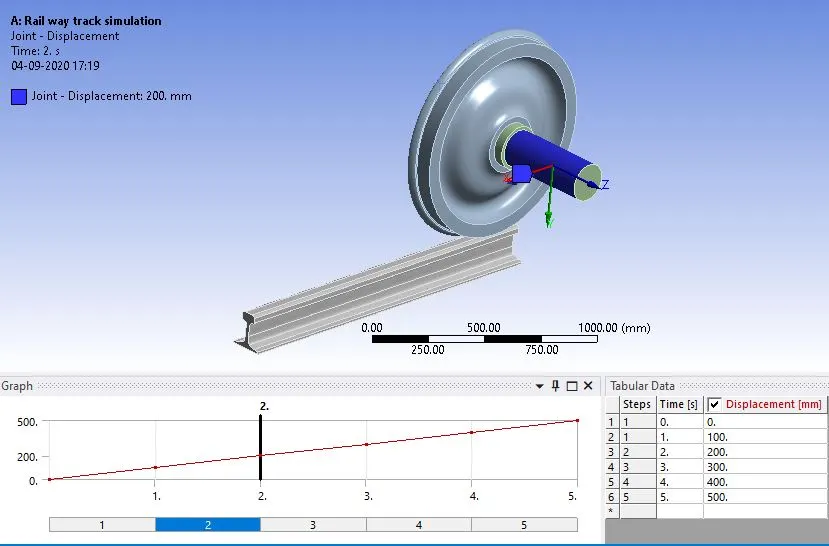
Displacement is given in a gradual manner of 5steps with 100mm displacement in each time step.
Bearing Load condition on the Wheel Hub:
The bearing load is imposed on the inner surface of the wheel hub.
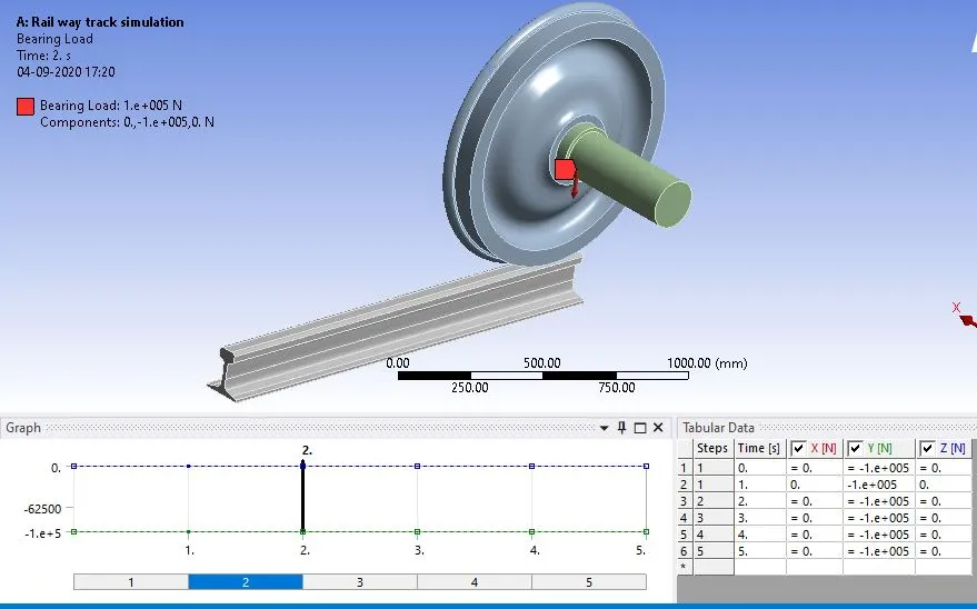
The first results are computed for a load of 100000N and then the load is increased to 50000N and again results are computed for the same.
Analytical Settings:
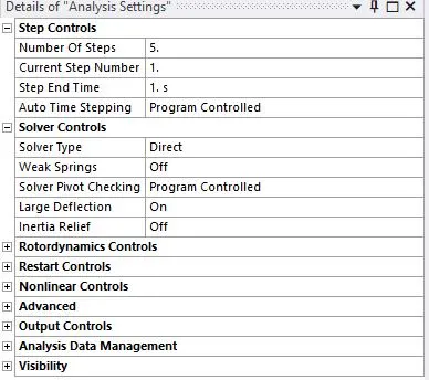
The analysis is done in 5-time steps. In which of the first time step auto time stepping is switched to program-controlled.
First-time step:
Remaining Time step:
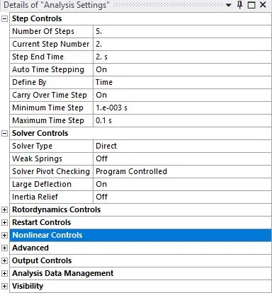
while for the rest of the steps it is switched ON and with the input of max time increment as 0.1 and min time increament set to 0.001 sec.
Results:
Case-1:
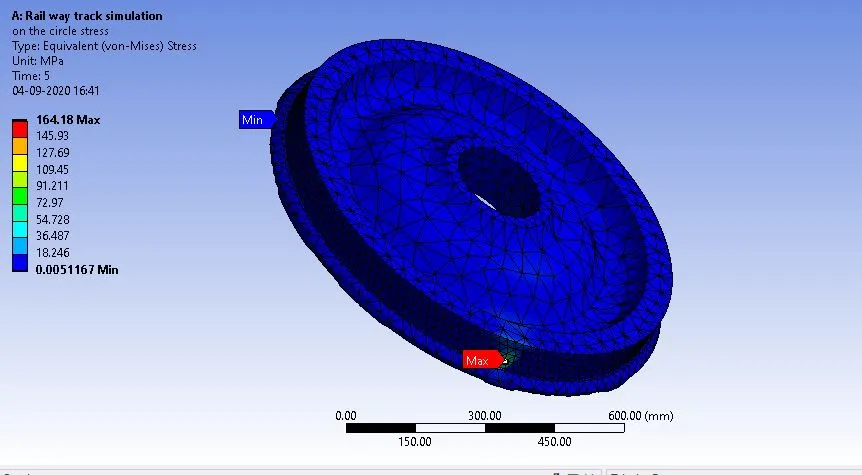
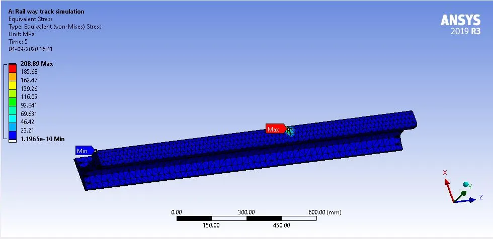
Rail wheel track showing stress distribution with a bearing load of 100000N
Equivalent stress on the wheel:
Equivalent stress on the Rail:
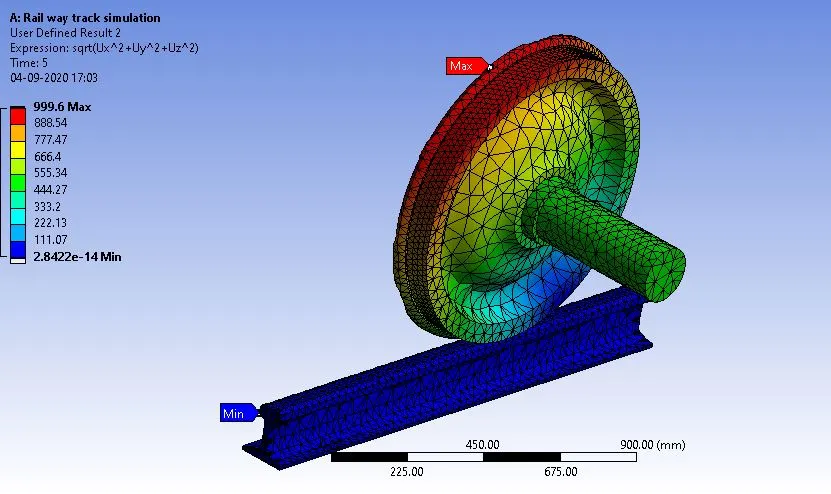
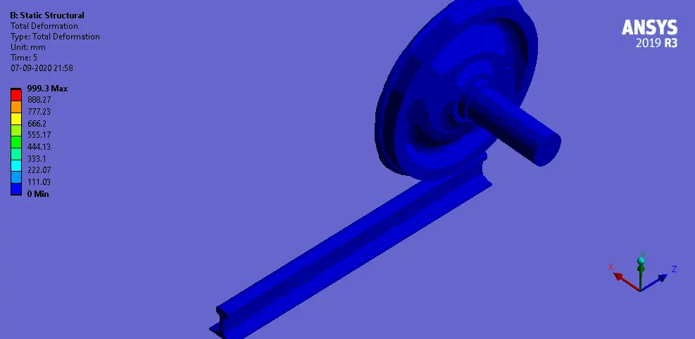
Total deformation
RailWheel-track Interfaces showing total deformation
Contract status:
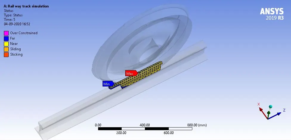
Contact Pressure:
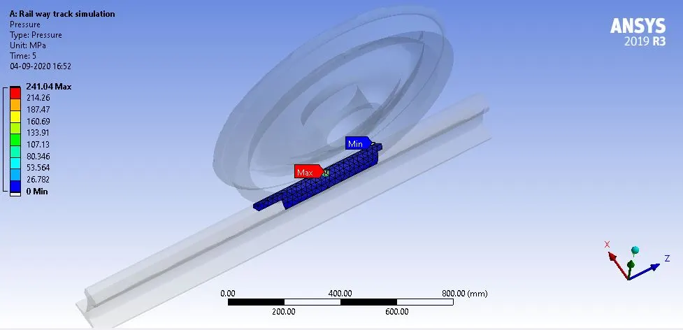
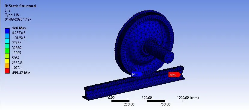
Fatigue Life:
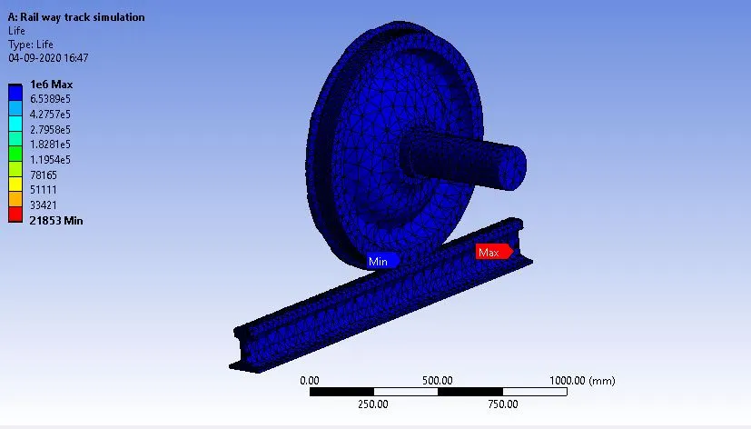
Case-2:
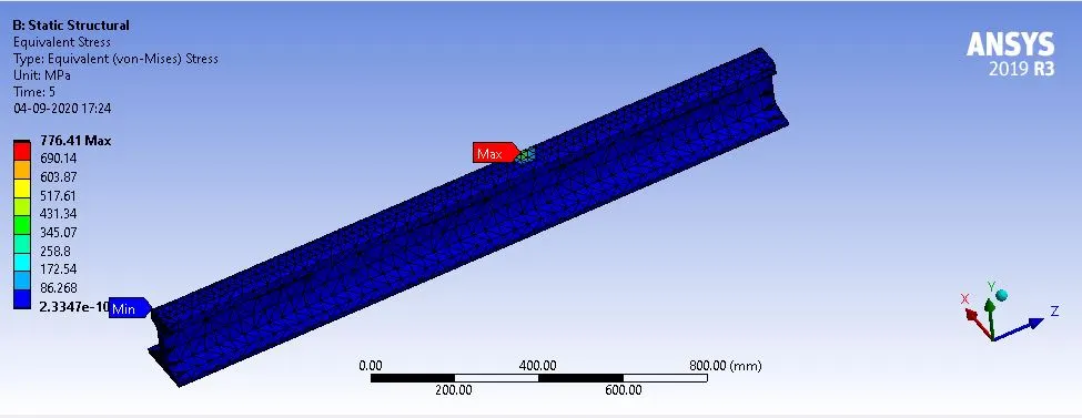
Rail wheel track showing stress distribution with a bearing load of 500000N
Equivalent stress on the wheel:
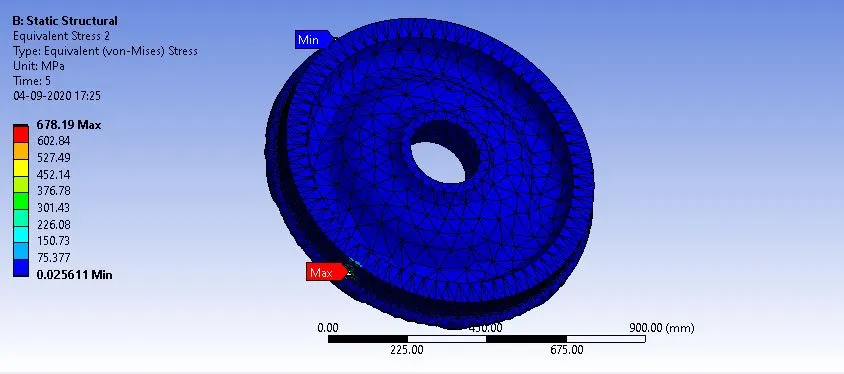
Equivalent stress on the Rail:
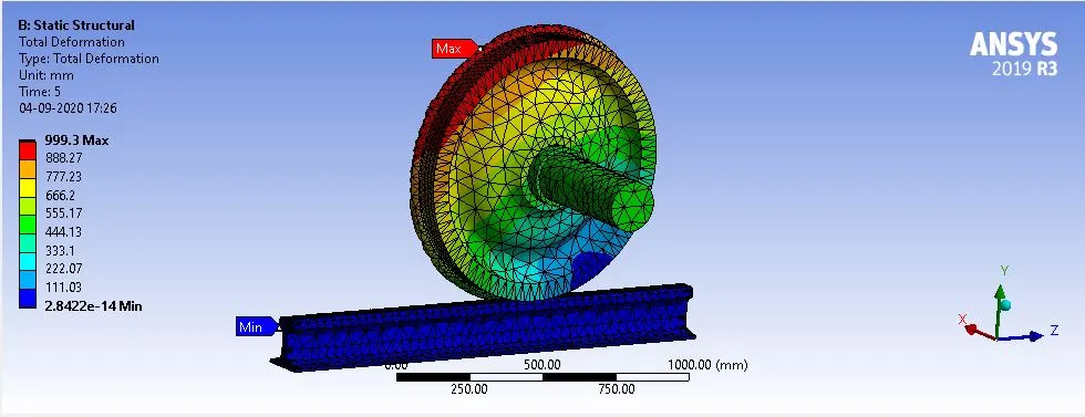
Total deformation
RailWheel-track Interfaces showing total deformation
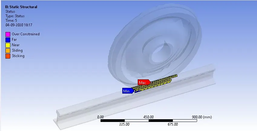
Contact status:
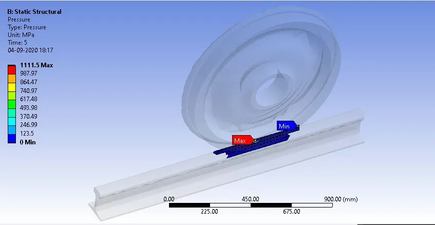
Contact Pressure:
Fatigue Life:
User-defined Result:
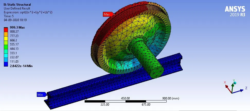
The user-defined result is obtained for the total deformation using the values of directional deformation along the three principal axes.
A Vector in cartesian coordinates is defined by its components along the three perpendicular axes i.e x,y, and z-axis.
`vec(A)=A_xhat(i)+A_yhat(j)+A_zhat(k)`
In order to get the magnitude of the vector,
`|vec(A)| = sqrt(A_x^2+A_y^2+A_z^2)`
Similarly, Deformation is also defined in the three mutually perpendicular directions knowns as directional deformation (U_x, U_y, U_z). So in order to get the total deformation.
Total deformation = `sqrt(U_x^2+U_y^2+U_z^2`
Total deformation
Total deformation using Expressing with a UDF:
Total deformation Animation:
Conclusion:
Total deformation has been found when using the expression in the user-defined area and that has become exactly the same as the one we got it from the original total deformation which is at the bearing load of 100000N is 999.6mm.
| Title | 100000N | 500000N |
| Total deformation | 999.6 | 999.3 |
|
Total deformation using UDF |
999.6 | 999.3 |
| Equivalent stress | 0.00156 | 0.00575 |