Week 3 Challenge : CFD meshing on Turbocharger
AIM:
To check for geometrical errors and create appropriate volumes for the given model, create and assign PIDs. Surface meshing with the given target lengths according to PIDs.
- Blade stage-1 = 1 mm
- Blade stage-2 = 1 mm
- Impeller = 2 mm
- Shaft rotor = 1 mm
- Turbo casing = 5 mm
- Compressor casing = 5 mm
- Inlet casing cover = 5 mm
Learning Outcomes:
- Geometry cleanup
- Surface meshing
- Volume meshing
Import the given geometry as shown below
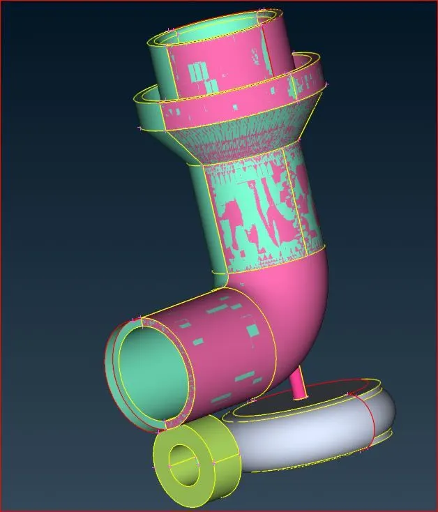
There are numerous issues, as we can see. In geometry, there are several flaws and gaps.
Thus, we can use ANSA's built-in geometry check.
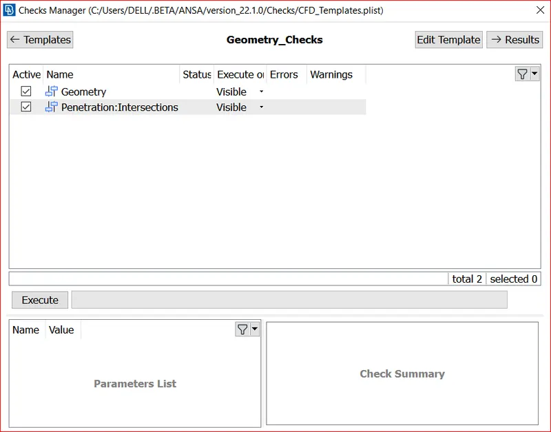
Select both geometry and Intersection and click execute.Following execution, we can identify every geometry mistake, allowing us to address each one individually.
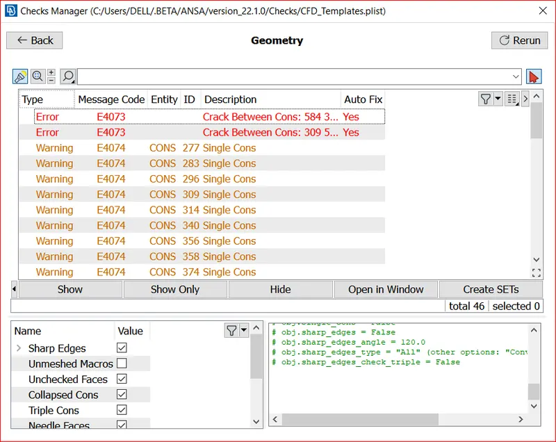
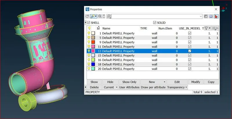
All of this demonstrates the geometry's free regions, which must be filled before meshing in order to avoid problems.
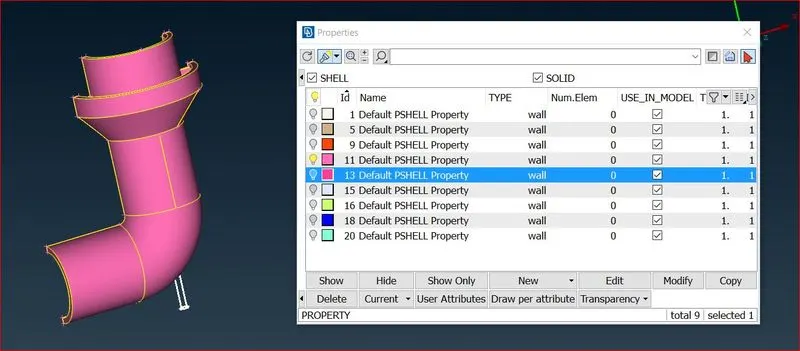
we can see overlaping face which can be deleted from the domain as per the requirement.
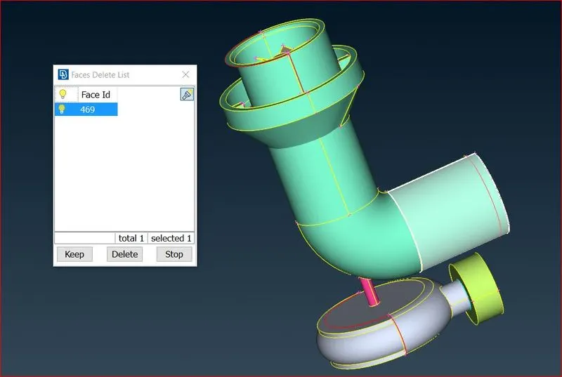
As a excess face is been observed from the domain of the compressure.so we can deleted the face and make the requried changes as per the geometry cleanup.
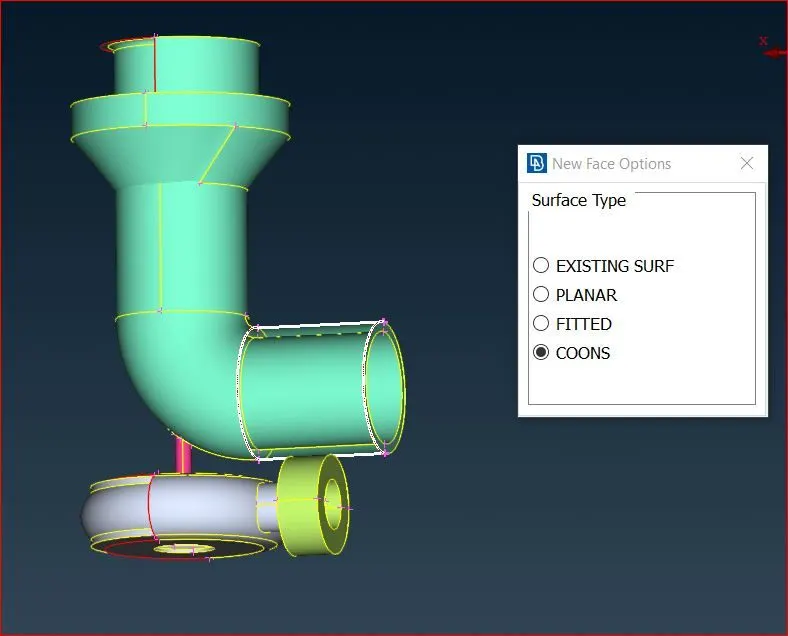
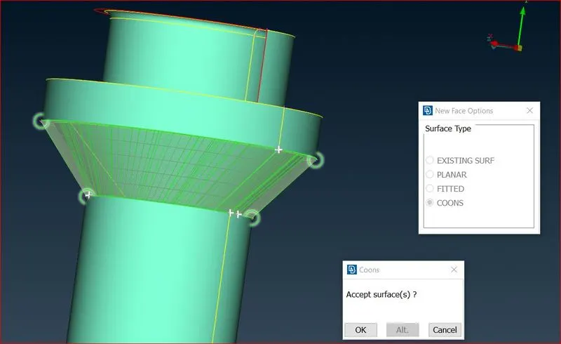
so to create faces we have to go for Topo - faces - New
- planer
- fitted
- coons
- existing
and we can use Fill hole option.We will choose these option according to the accuracy of the outcomes.To Fill these holes select option then select the cons (we can select entities by one by one or can select one loop by loop select in below left)then middle click and select surface.on the curved surface we will use coons or fitted(because planer can not fill hole on curved surface properly).
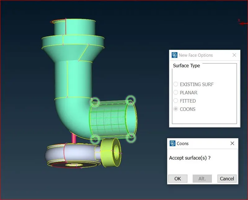
We can see any overlap at the traped protion of the compressure Cabient cone.For clearing that issue we can use the intersection option to remove the overlap.
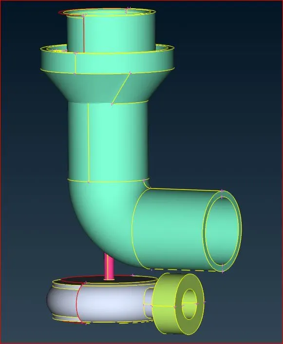
By using the cut plane we need to remove the unwanted faces in the geometry as shown below.
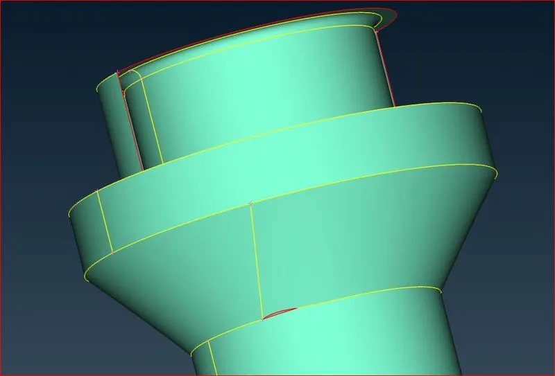
By using the cut plane we need to remove the unwanted faces in the geometry as shown below.
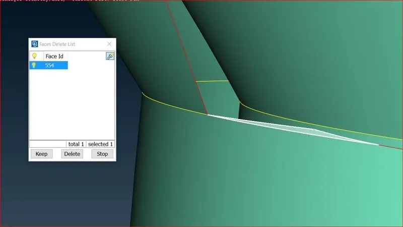
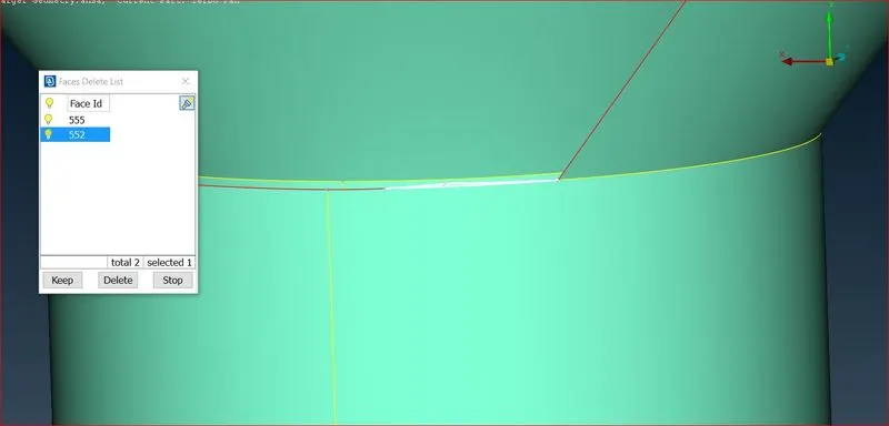
By using the cut plane we need to remove the unwanted faces in the geometry as shown below.so to create faces we have to go for Topo - faces - New
- planer
- fitted
- coons
- existing
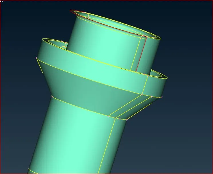
We can see a clean face which has no uneven surface on the compressure casing and we will choose these option according to the accuracy of the outcomes.To Fill these holes select option then select the cons (we can select entities by one by one or can select one loop by loop select in below left)then middle click and select surface.on the curved surface we will use coons or fitted(because planer can not fill hole on curved surface properly).
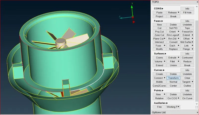
so to create faces we have to go for Topo - faces - New
- planer
- fitted
- coons
- existing
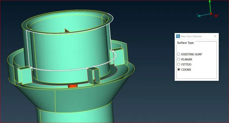 19.
19.
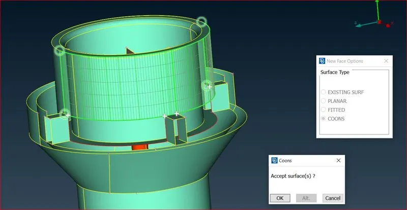
select option, then select the cons (we can select entities one by one or one loop by loop in the lower left), then middle click and select surface. We will use coons or fitted on the curved surface (because planer can not fill hole on curved surface properly).
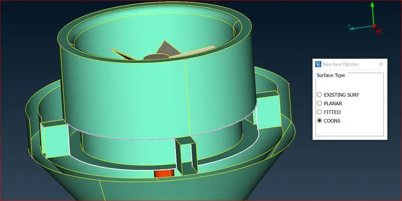
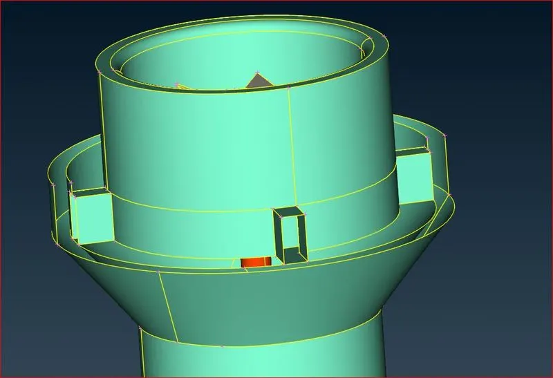
We can see a clean face with no uneven surface on the compressure casing, and we will choose these options based on the accuracy of the results.
Disconnect some part of geometry or mesh from the rest of the mode we can the function Transform [Move] and translate these entities by a distance which is requried.
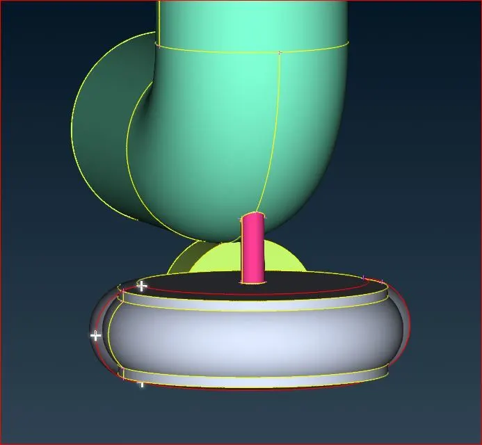
we need to select the Mirror 3 points plane and select the three points as shown in the plane.
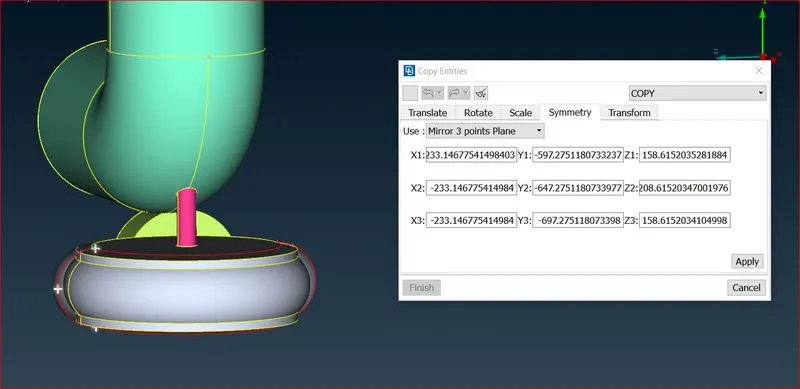
And then click ok, we can see a mirror of the required plane as shown in the geometry in the below images.
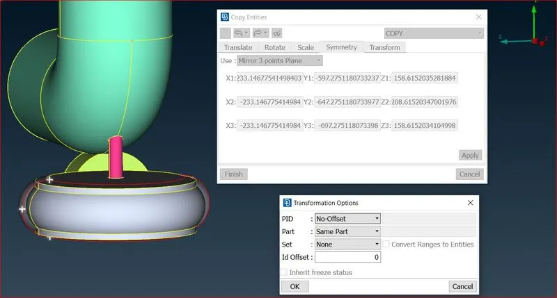
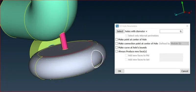
Use Fill hole option and we will choose these option according to the accuracy of the outcomes and a clean face with no uneven surface
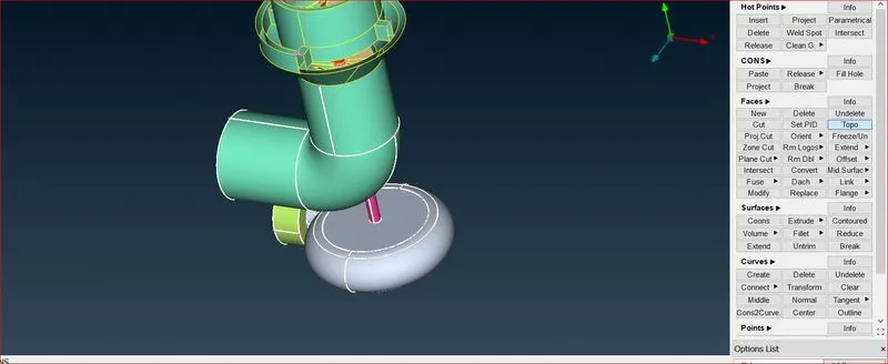
clean face with no uneven surface and click on the Topo for the check uneven connectivity.
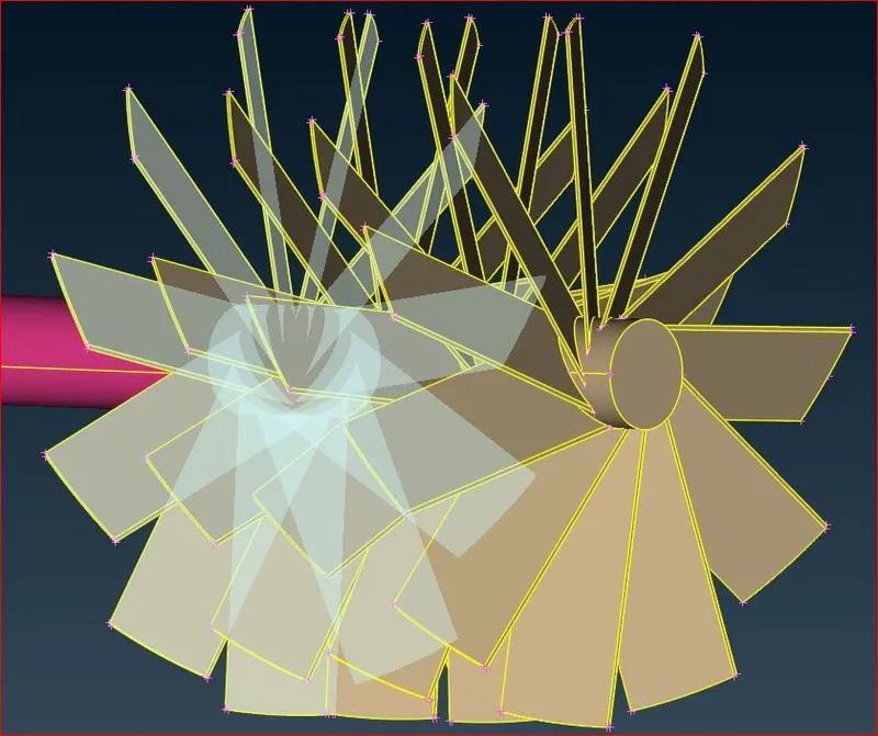
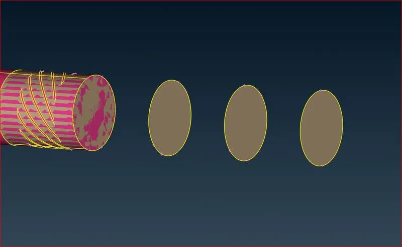
All the internal faces which are inside the shaft and the Turbine blades are need to removed becasue of the Glitch or the overlaping faces.
In order to easily extract say the exterior Faces, if the domain of interest is the flow surrounding the shaft and compresser casing the user can activate the Isolate [Skin] function.
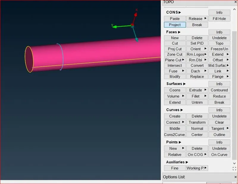
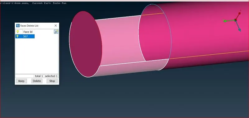
This function does not require perfectly connected geometry, red CONS and intersections may be present. Still, some major openings, like the inlet and outlet, should be closed by the user.
Here they must specify to isolate Outer or Inner Faces.
Compress
Before outputting the model it is recommended that you clear the database from any empty or unused grids, PIDs, etc, using the function Compress.
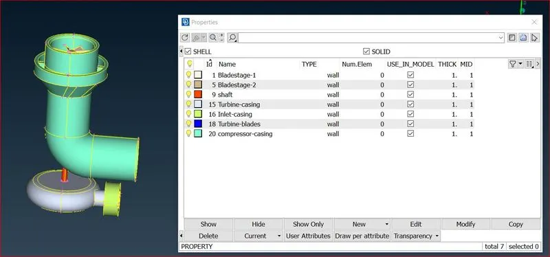
Tools General>RenumberModel to renumber all PIDs and elements.
As shown above we can fix all the gaps in geometry, also ANSA shows alternate option in all the faces to create a face according our requirement
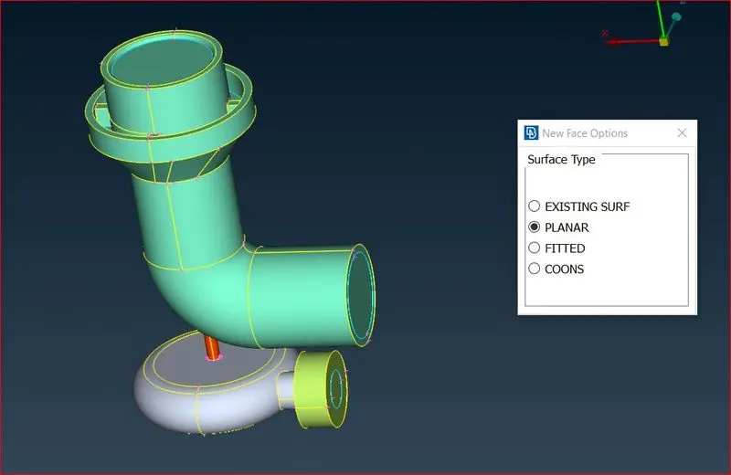
After fixing all the holes also the Inlet and Outlet the geometry looks like this
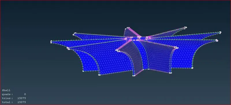
In mesh - spacing - Auto cfd -peremeter then select the geometry and middle click and then select the max length as 1.5mm and minimum length as 0.5mm and ok, same do for macros.
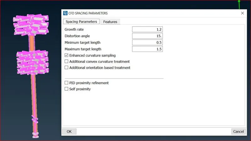
We need to Frozen the required parts which haven mesh previously, to keep the parts at required part.
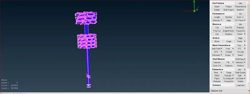
Then in mesh generation cfd visible.
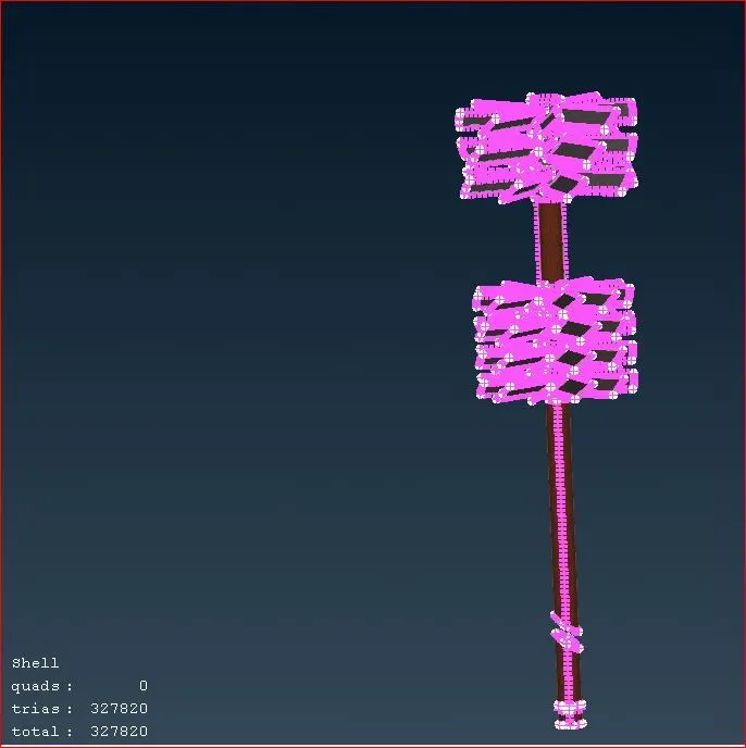
In mesh - spacing - Auto cfd -peremeter then select the geometry and middle click and then select the max length as 2.5mm and minimum length as 1.5mm and ok, same do for macros.
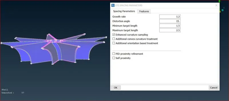
We need to Frozen the required parts which haven mesh previously, to keep the parts at required part.
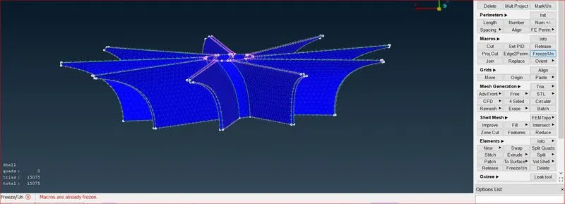
Then in mesh generation cfd visible.
In mesh - spacing - Auto cfd -peremeter then select the geometry and middle click and then select the max length as 5.5mm and minimum length as 4.5mm and ok, same do for macros.
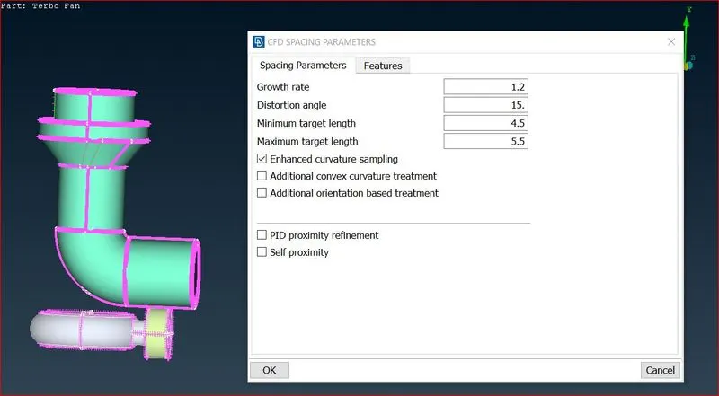
We need to Frozen the required parts which haven mesh previously, to keep the parts at required part.
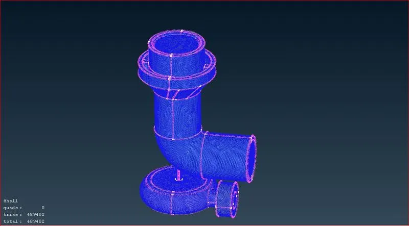
Define all parts which need to be meshed.
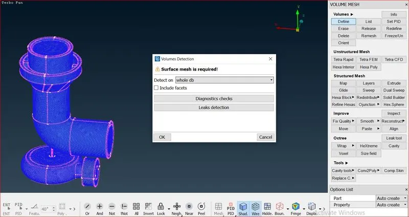
we need to remove the internal volume inside the Pressure valve because we are considering it as Buff body in the domain.
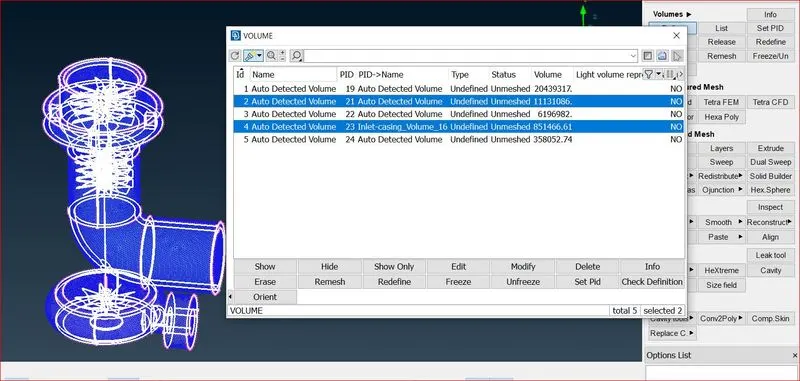
Now we need to assign the type to tetra CFD and check the status for the mesh.
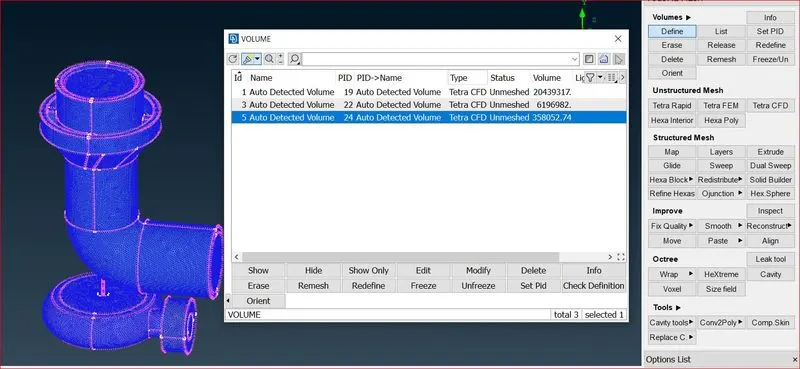
Rightclick on the status and mesh it as per the defined Deteched volume.
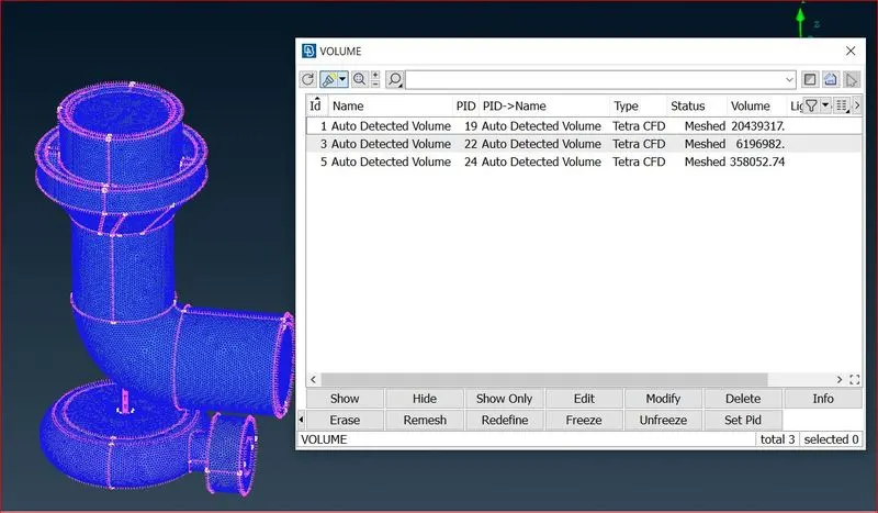
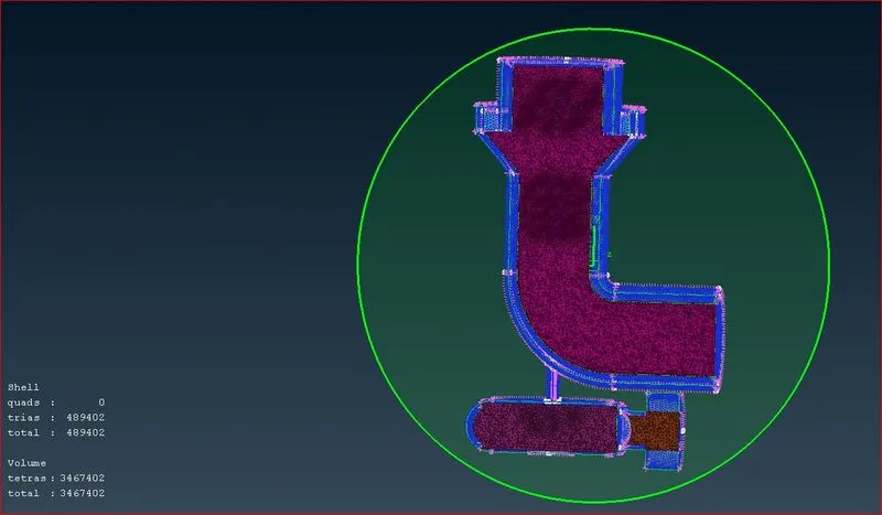
Volume mesh for the Turbocharger Domian
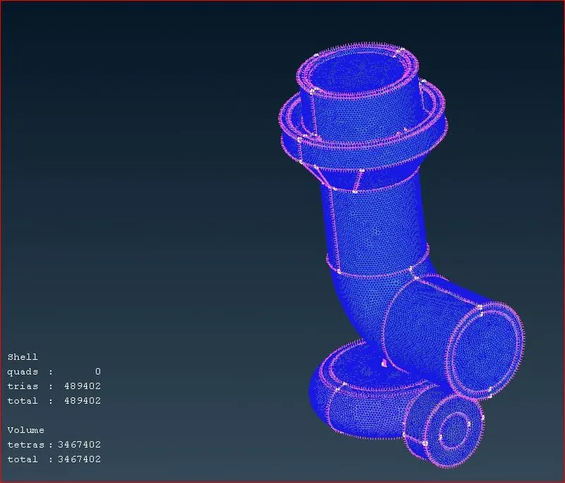
Cut-Plane for Volume mesh
Conclusion:
- Blade stage-1 = 1 mm
- Blade stage-2 = 1 mm
- Impeller = 2 mm
- Shaft rotor = 1 mm
- Turbo casing = 5 mm
- Compressor casing = 5 mm
- Inlet casing cover = 5 mm
Thus, geometrical errors such as single, double, and triple con are checked, PIDs are assigned based on the requirement, and the surface is generated for the given target lengths.The mesh length for the given parts was maintained to increase the accuracy of smaller parts. The volumetric meshing is then successfully completed for the required volume.
Link for the volume mesh file
https://drive.google.com/drive/folders/11ic5OaTQqSGD0yiiDhL-Gu0_5JnY9T5D