Week 2 Challenge : Surface meshing on a Pressure valve
Aim:
To create three distinct meshes with three different target lengths, to generate surface meshing on a given model.
Geometry:
The model provided has many geometrical errors which are to be corrected before meshing the domain.
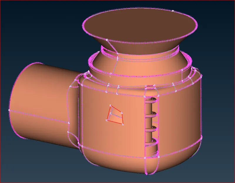
There are numerous issues, as we can see. In geometry, there are several flaws and gaps.
Thus, we can use ANSA's built-in geometry check.
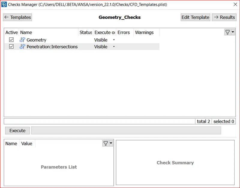
Select both geometry and Intersection and click execute.Following execution, we can identify every geometry mistake, allowing us to address each one individually.
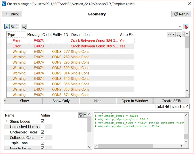
All of this demonstrates the geometry's free regions, which must be filled before meshing in order to avoid problems.
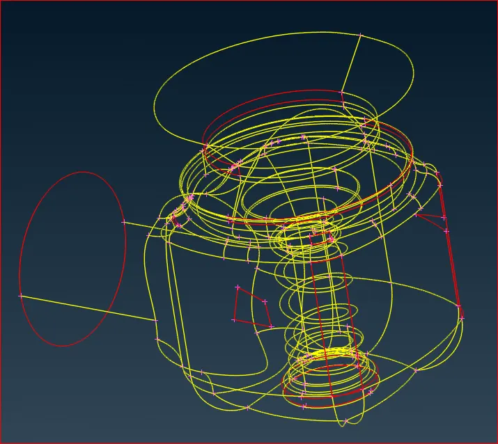
Everything here shows the geometry's free zones, which must be filled prior to meshing in order to prevent issues.
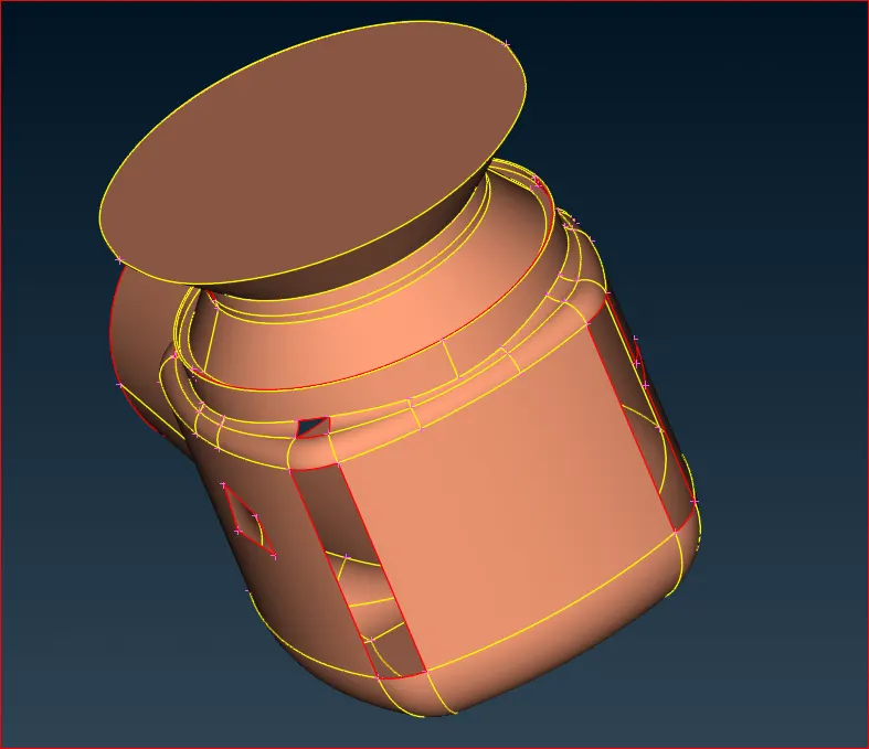
Here we have to drive out all the single cons (junction between surfaces) and keep double cons and sometimes keep triple cons.
so to create faces we have to go for Topo - faces - New
- planer
- fitted
- coons
- existing
and we can use Fill hole option.We will choose these option according to the accuracy of the outcomes.To Fill these holes select option then select the cons (we can select entities by one by one or can select one loop by loop select in below left)then middle click and select surface.on the curved surface we will use coons or fitted(because planer can not fill hole on curved surface properly).
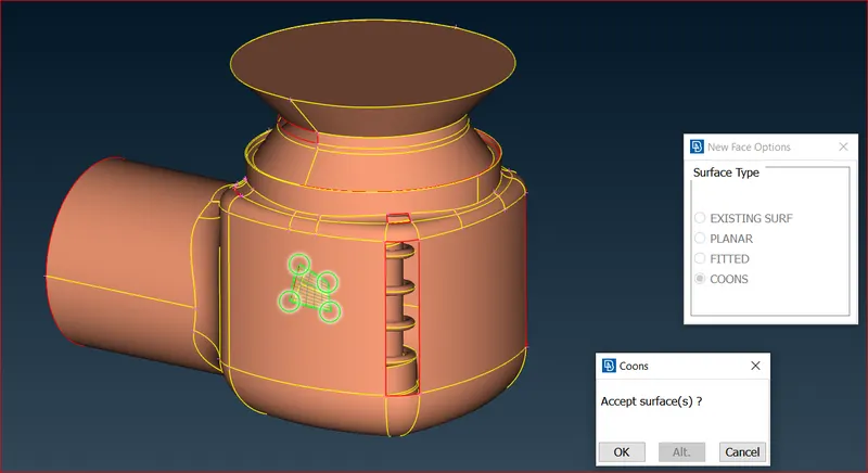
After selecting this surface select the triangle by coons with loop .Like this we have to fill all the geometrical holes so that no single cons remains.
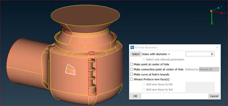
As shown above we can fix all the gaps in geometry, also ANSA shows alternate option in all the faces to create a face according our requirement
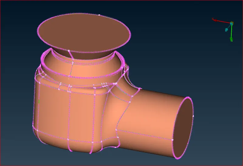
After fixing all the holes also the Inlet and Outlet the geometry looks like this
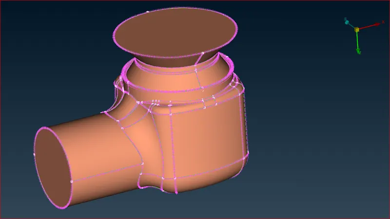
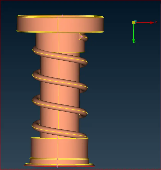
After that, we'll fix the intersection error. Now that we can see the spring piercing the geometry from within, we are concealing all other parts of the geometry except from the spring and the column.
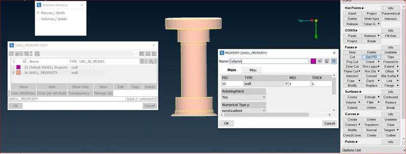
Now we want to select the spring and the column as another pids for convenience purpuse. For this in the bottom select the PID instead of entity and in the drop down menu in PID select the PID region .
Column Region:
Spring Region:
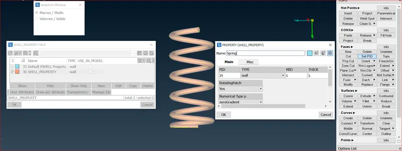
Then select the not option and hide the spring .Before that lock the geometry of spring and column so that after clicking all overall geometry does not came.Then hide the spring and in Topo-Faces-set pids-macros select the column and then middle click and then New and in shell property name it as column and ok and then on the pid menu double left click on column pid.Like this create the spring pid.
Now we are going for meshing . so first select all pids and then in . we are selecting mesh length by spacing not by mesh length so as to get the mesh more accurately.
5 mm mesh length:
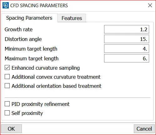
In mesh - spacing - Auto cfd -peremeter then select the geometry and middle click and then select the max length as 6mm and minimum length as 4mm and ok, same do for macros.Then in mesh generation - cfd visible.
Spacing Parameter and Macro Parameter.
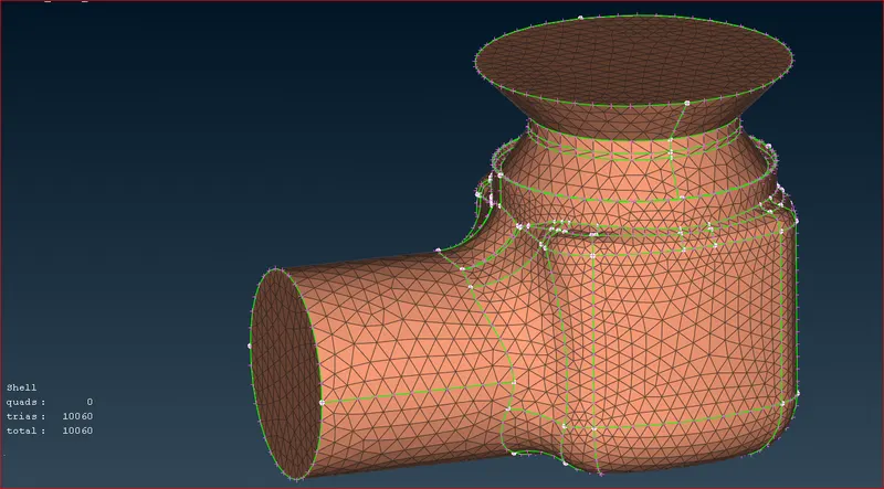
Mesh on the Pressure Valve
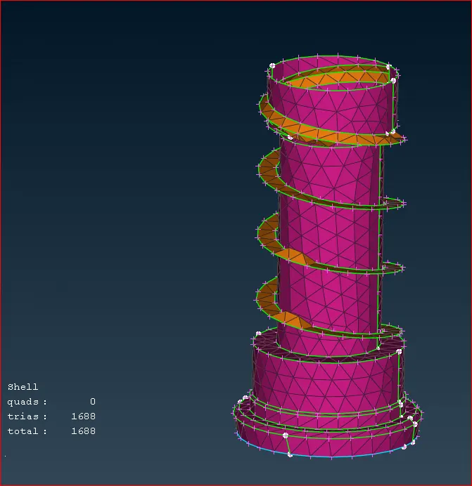
Mesh on the Column and Spring.
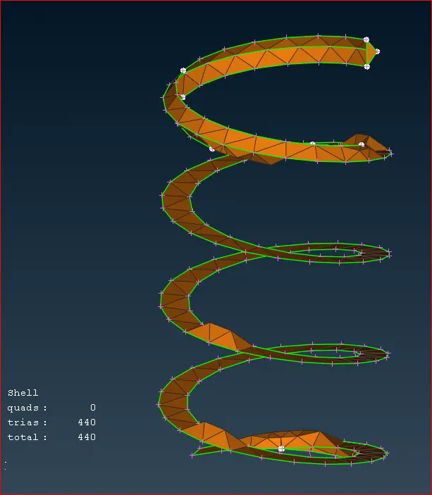
Mesh on the Spring
3 mm mesh length:
select the max length as 6mm and minimum length as 3mm
Spacing Parameter and Macro Parameter.
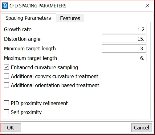
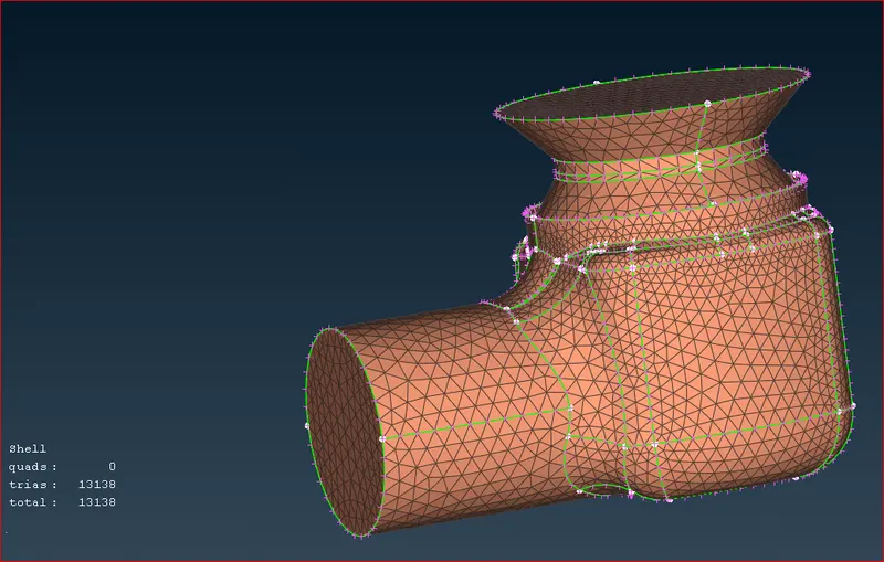
Mesh on the Pressure Valve
Mesh on the Column and Spring.
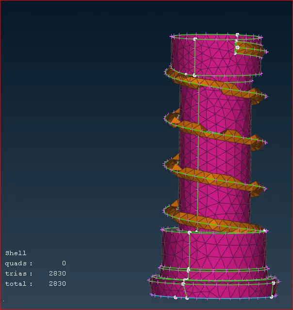
Mesh on the Spring
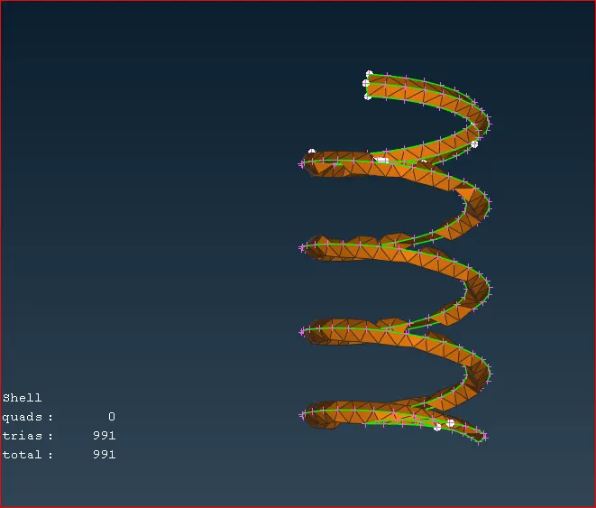
1 mm mesh length:
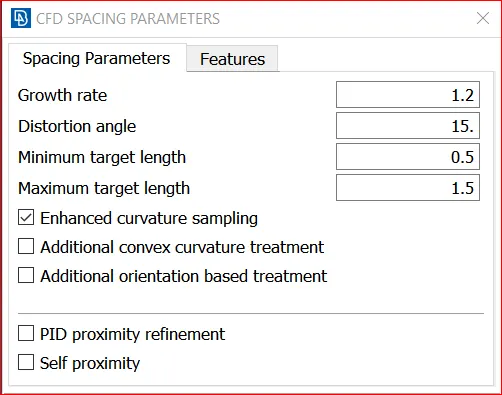
select the max length as 1.5mm and minimum length as 0.5mm
Spacing Parameter and Macro Parameter.
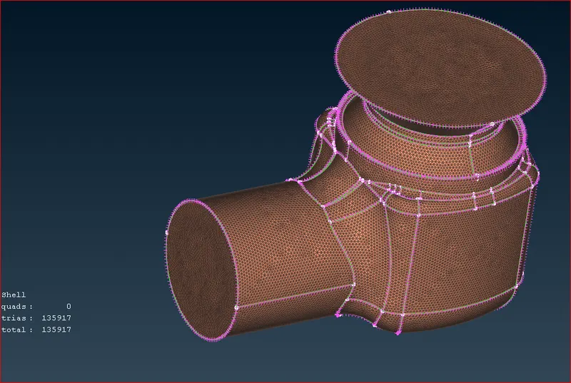
Mesh on the Pressure Valve
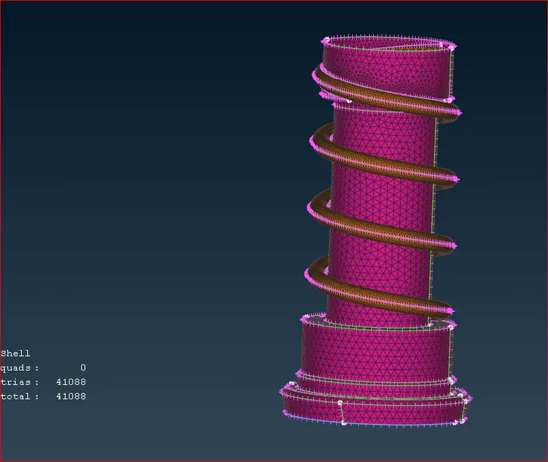
Mesh on the Column and Spring.
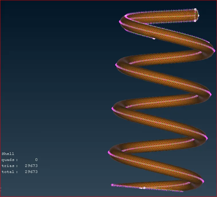
Mesh on the Spring
we need to remove the internal volume inside the Pressure valve because we are considering it as Buff body in the domain.
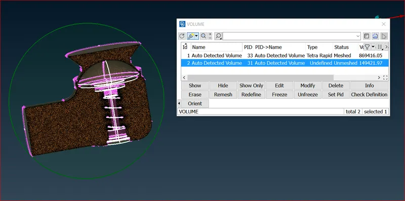
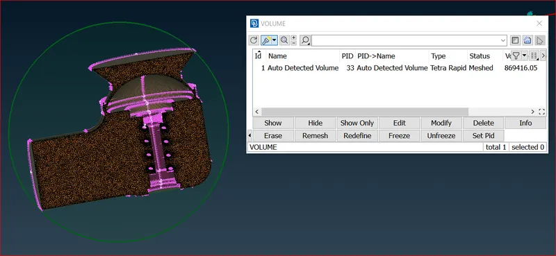
Volume mesh for the 1mm mesh
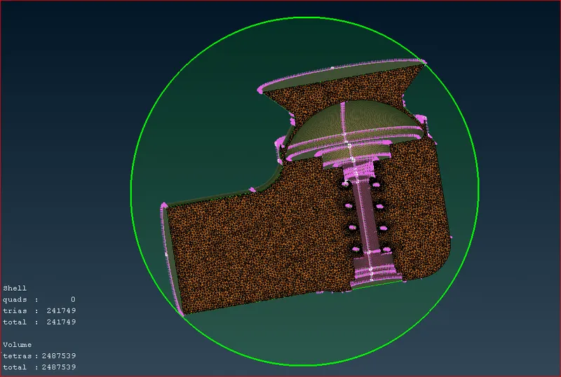
Conclusion:
- The accuracy increases with finner mesh size, but so does the calculation time.
- We can create two target lengths based on the size of the parts and the required accuracy; in this case, the outer casing mesh size can be 3mm, which is not too large and not too fine for a good and accurate result.
- The mesh length for smaller parts, such as the spring and the column head, can be 1mm, increasing the accuracy for smaller parts.
Link for the volume mesh file 1mm
https://drive.google.com/drive/folders/16d0Yrz-gCiBb7lotrLpvPVOzILTJDHFs