Verification of Weld Joints structural analysis
AIM:
To study and perform analysis on the weld joints using different materials for the welds and compare the results with each other
1 To simulate three different types of welding joints using three different weld materials.
2. To find out the directional deformation and equivalent strain experienced by the setup.
3. To identify the weld joint that experiences the highest equivalent stress in each case and compare the results for all three cases.
Introduction:
Welding is a fabrication process that joins materials, usually metals or thermoplastics, by using high heat to melt the parts together and allowing them to cool, causing fusion. Welding is distinct from lower temperature metal-joining techniques such as brazing and soldering, which do not melt the base metal.
In addition to melting the base metal, a filler material is typically added to the joint to form a pool of molten material (the weld pool) that cools to form a joint that, based on weld configuration (butt, full penetration, fillet, etc.), can be stronger than the base material (parent metal). Pressure may also be used in conjunction with heat or by itself to produce a weld. Welding also requires a form of shield to protect the filler metals or melted metals from being contaminated or oxidized.
Many different energy sources can be used for welding, including a gas flame (chemical), an electric arc (electrical), a laser, an electron beam, friction, and ultrasound. While often an industrial process, welding may be performed in many different environments, including in open air, underwater, and in outer space. Welding is a hazardous undertaking and precautions are required to avoid burns, Electric shock, vision damage, inhalation of poisonous gases and fumes, and exposure to intense ultraviolet radiation.
Until the end of the 19th century, the only welding process was forge welding, which blacksmiths had used for millennia to join iron and steel by heating and hammering. Arc welding and oxy-fuel welding were among the first processes to develop late in the century, and electric resistance welding followed soon after. Welding technology advanced quickly during the early 20th century as world wars drove the demand for reliable and inexpensive joining methods. Following the wars, several modern welding techniques were developed, including manual methods like shielded metal arc welding, now one of the most popular welding methods, as well as semi-automatic and automatic processes such as gas metal arc welding, submerged arc welding, flux cord arc welding, and electro slag welding. Developments continued with the invention of
- laser beam welding
- Electron beam welding
- Magnetic pulse welding
- Friction stir welding
In the latter half of the century. Today, as science continues to advance, robot welding is commonplace in industrial settings, and researchers continue to develop new welding methods and gain a greater understanding of weld quality.
Geometry
To verify the weld in the setup we use the static structural tool in the analysis system tool to define the geometry and other input parameters.
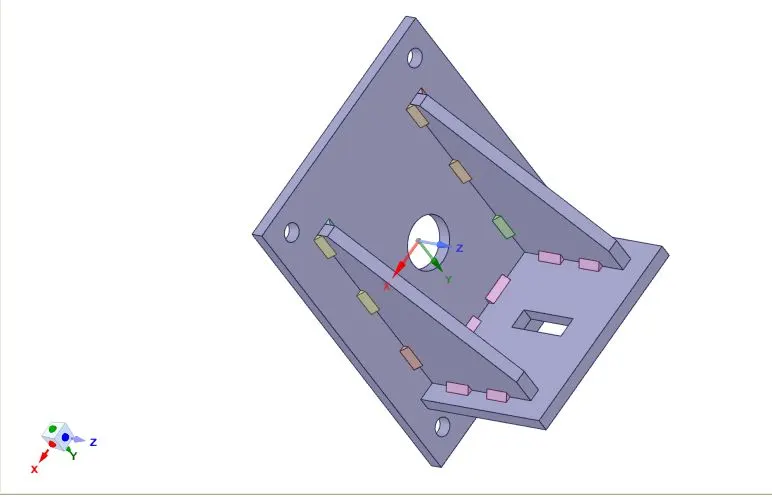
The cad model is imported and viewed in space claim and making sure there are no errors in the geometry.
Materials:
Weld Material used
Case 1. Stainless Steel: In this case, the material of the plates must also be the same. Used Stainless steel for both weldments and plates. No need to add flux to the weldments.
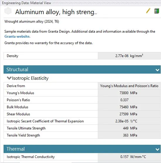
Case 2. Aluminium Alloy: The material to be chosen for this case is Aluminium alloy(high strength, wrought). [Plate material to be used is stainless steel]
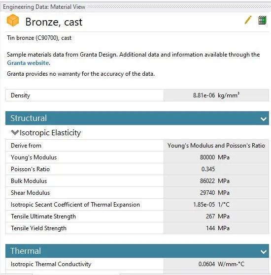
Case 3.Bronze: In order to simulate "Brazing", you should be using bronze as the weld material. Assign Stainless Steel to both plates and Copper to the "Ribs".
Contacts:
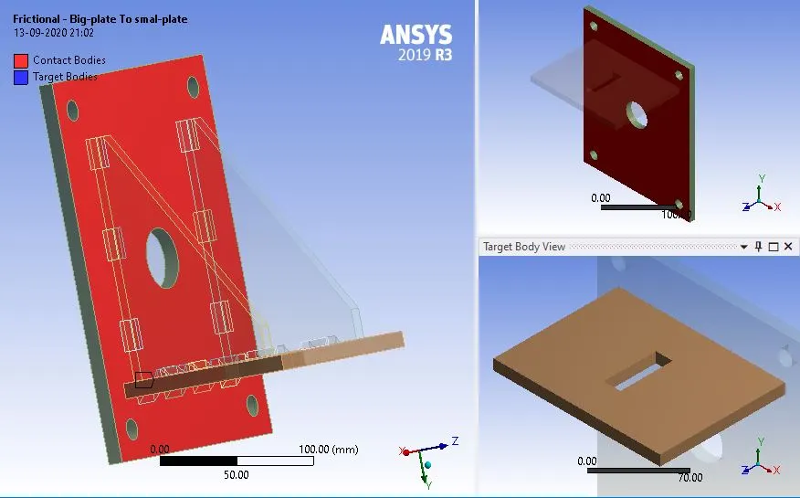
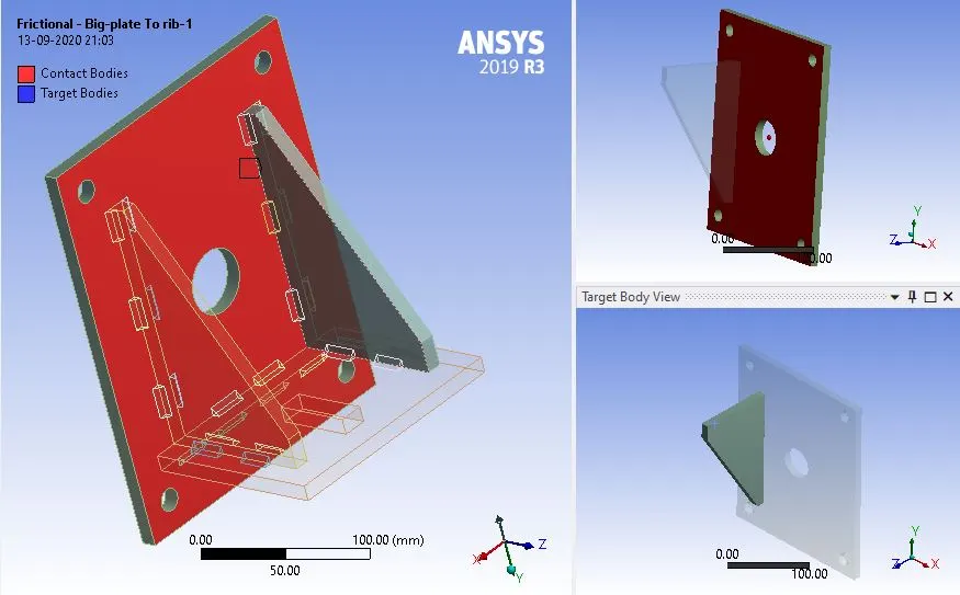
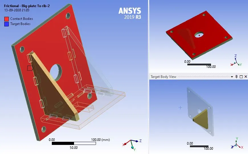
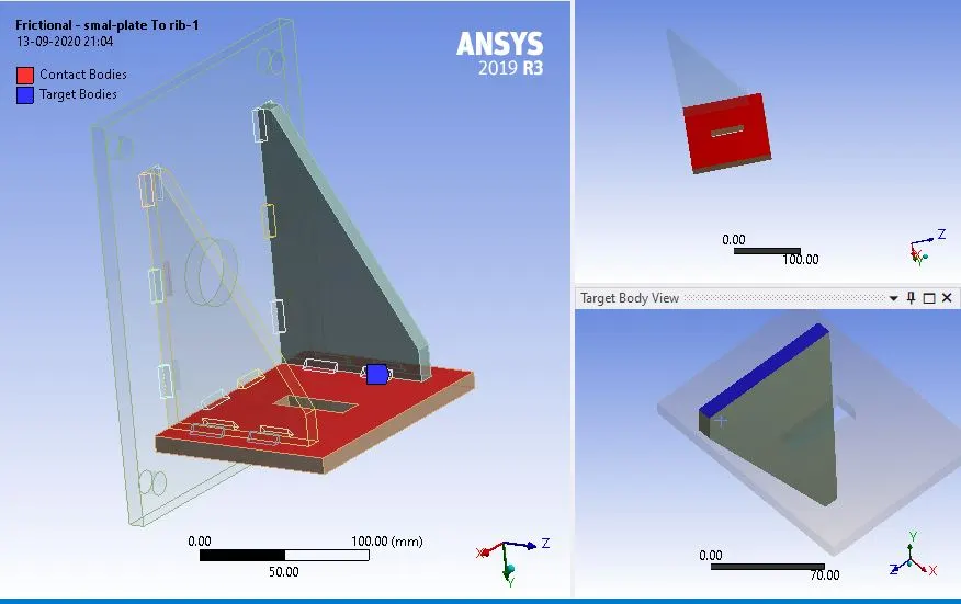
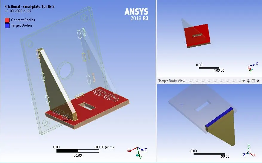
The direct contact between the ribs and plates as a frictional contact with a frictional coefficient of 0.2 since all the plates are flat the contact and the target can be chosen arbitrarily for all the contacts considering the advantages of using Augmented Lagrange to prevent interpenetrations it is used as a formulation for all frictional contacts.
Frictional Contact between Big plate to small plate:
Frictional Contact between Big plate to rib-1:
Frictional Contact between Big plate to rib-2:
Frictional Contact between small plate to rib-1:
Frictional Contact between small plate to rib-2:
On the other hand, since all the welded joints have to be fixed to the plates they are modeled as bonded joints with arbitrarily contact and target program-controlled formulation was used for all the weld joints.
Mesh:
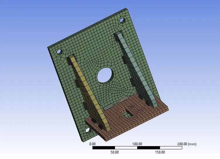
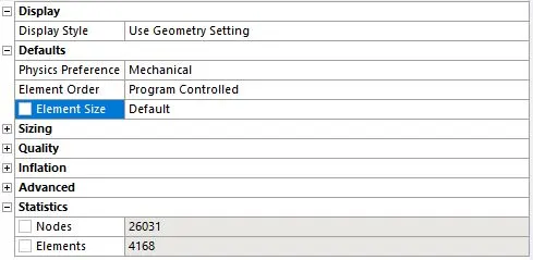
The appropriate element size was finalized by iteration default element size and a body mesh is used with 7mm refinement on the plates of the geometry was finalized and the total no of nodes and elements are shown below.
The meshed model image and mesh metric graph can be seen below:
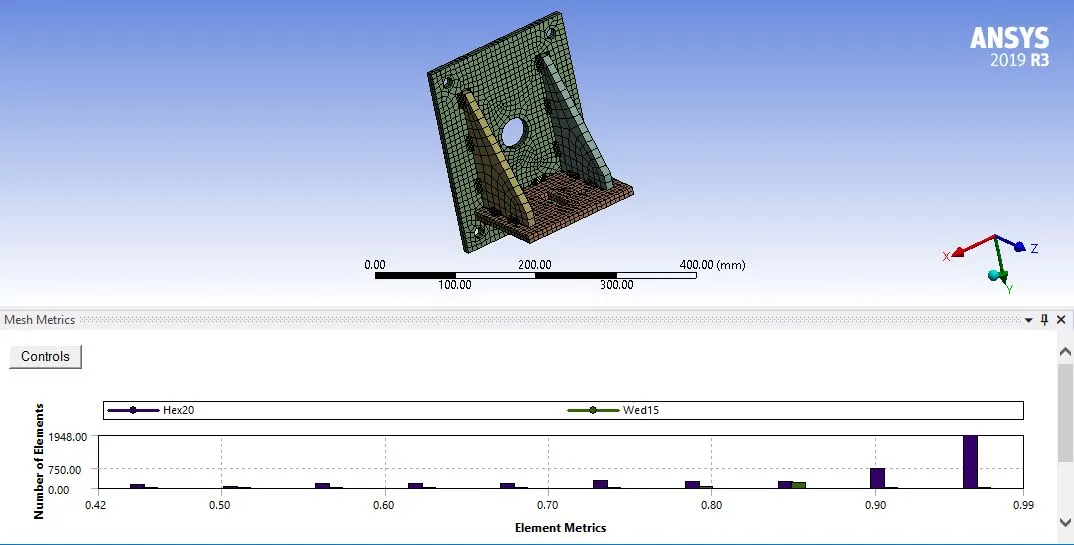
The mesh metric is utilized to identify the elements according to their quality. The quality of the mesh is acceptable as most of the elements lie within a high-quality range of 0.9-1.0.
Analysis Settings:
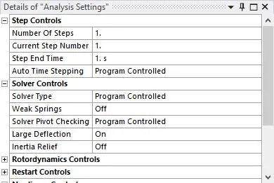
The analysis is set up for 1 step. This does not control the time step but is only an indication of points where boundary changes. the time step is auto controlled by specifying the initial, Minimum and Maximum time step.
Boundary conditions:
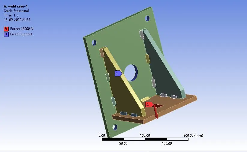
The overall boundary conditions are shown below
Fixed Support:
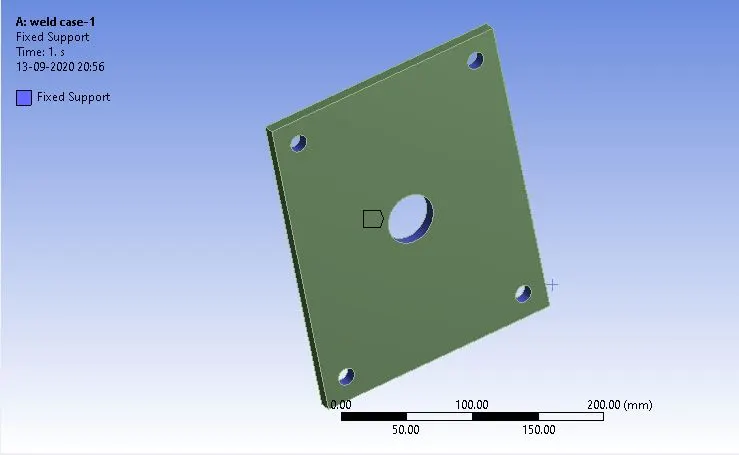
The fixed support is set up at the 5 holes of the base plate.
Force Load:
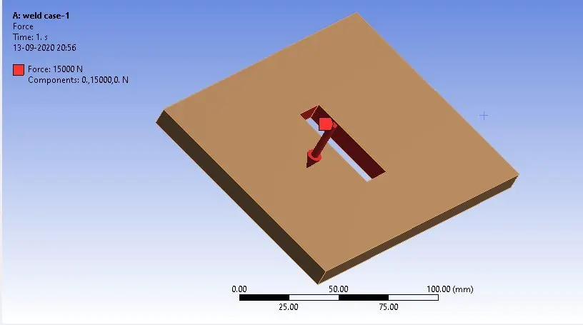
A 15000N force is applied to the rectangular hole of the sub-plate in the Y-direction
Result:
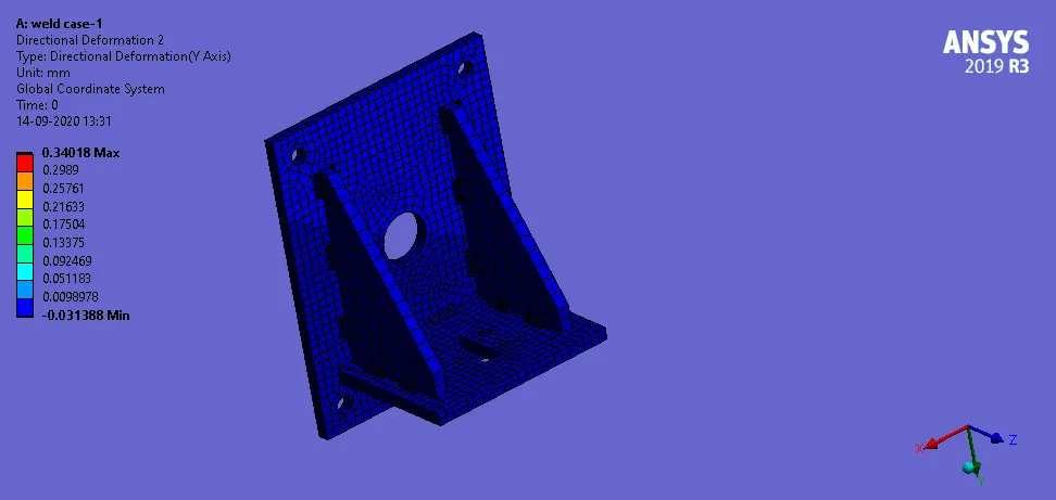
Case 1. Stainless Steel: In this case, the material of the plates must also be the same. Used Stainless steel for both weldments and plates. No need to add flux to the weldments.
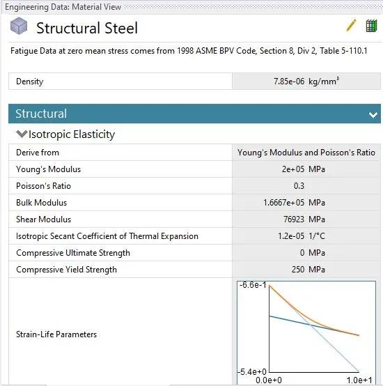
Material:
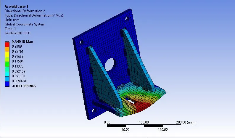
Directional Deformation experienced by the setup.
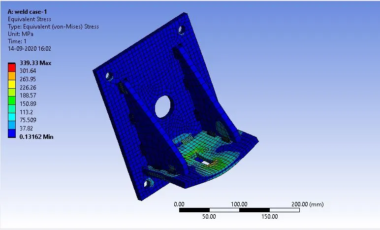
Equivalent strain experienced by the setup.
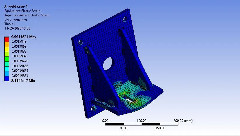
Equivalent strain experienced by the setup:
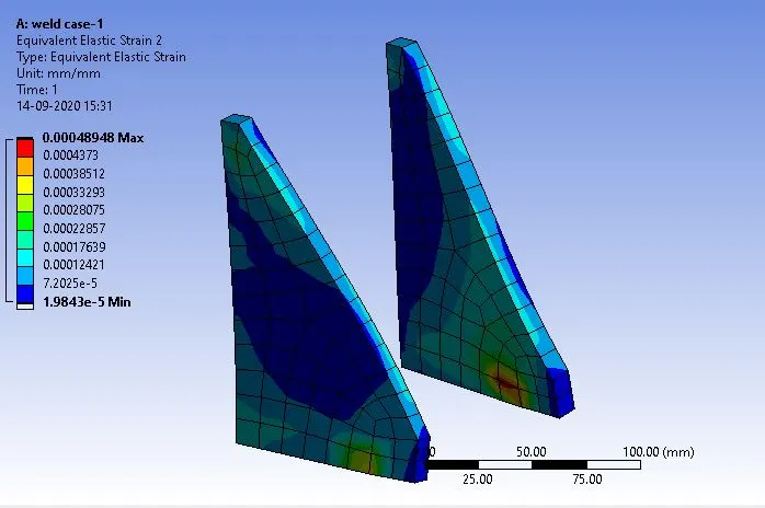
Equivalent strain experienced by the Ribs:
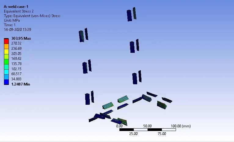
The weld joint that experiences the highest equivalent stress.
Animation for the Directional Deformation experienced by the setup.
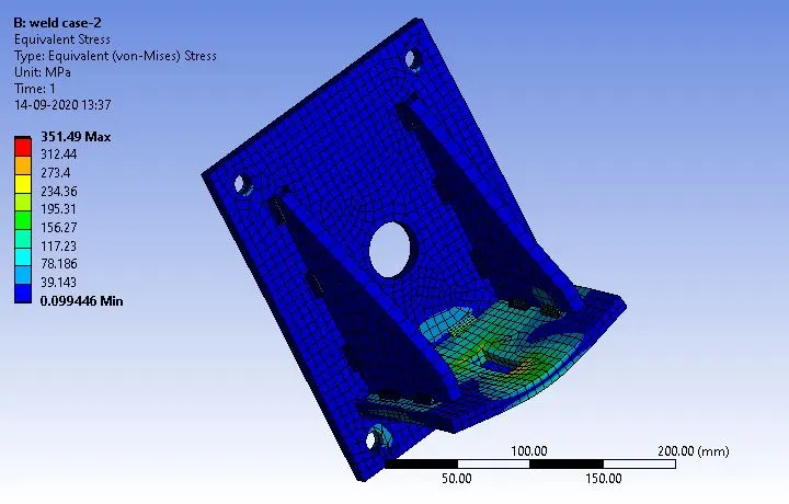
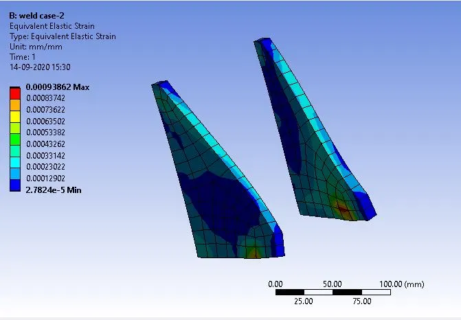
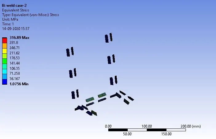
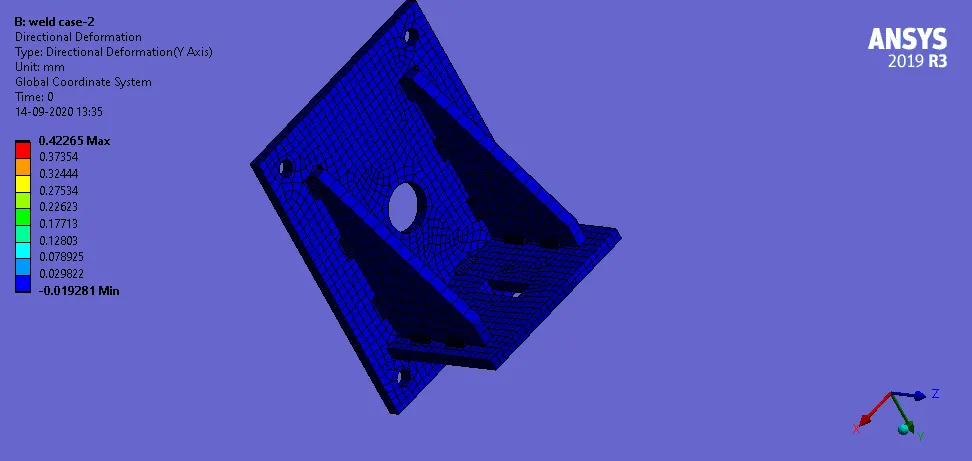
Case 2. Aluminium Alloy: The material to be chosen for this case is Aluminium alloy(high strength, wrought). [Plate material to be used is stainless steel]
The plate material used is stainless steel.
The Aluminium alloy(high strength, wrought) for remain ribs.
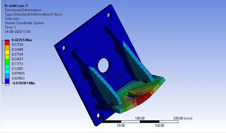
Directional Deformation experienced by the setup.
Equivalent strain experienced by the setup.
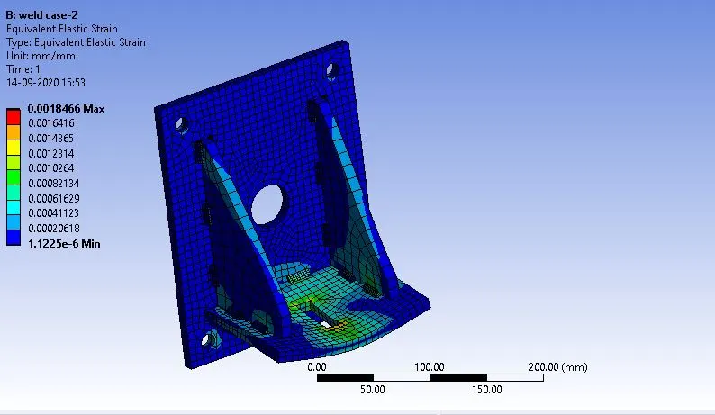
Equivalent strain experienced by the setup:
Equivalent strain experienced by the Ribs:
The weld joint that experiences the highest equivalent stress.
Animation for the Directional Deformation experienced by the setup.
Case 3.Bronze: In order to simulate "Brazing", you should be using bronze as the weld material. Assign Stainless Steel to both plates and Copper to the "Ribs".
The plate material used is stainless steel.
bronze as the weld material.
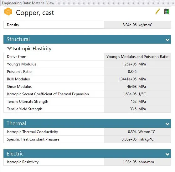
Copper to the "Ribs"
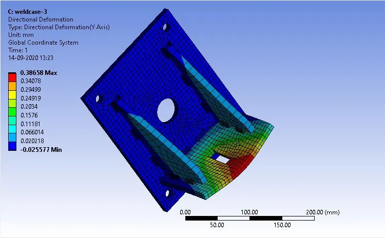
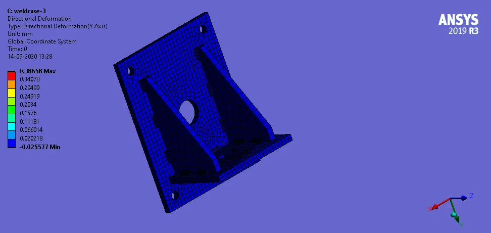
Directional Deformation experienced by the setup.
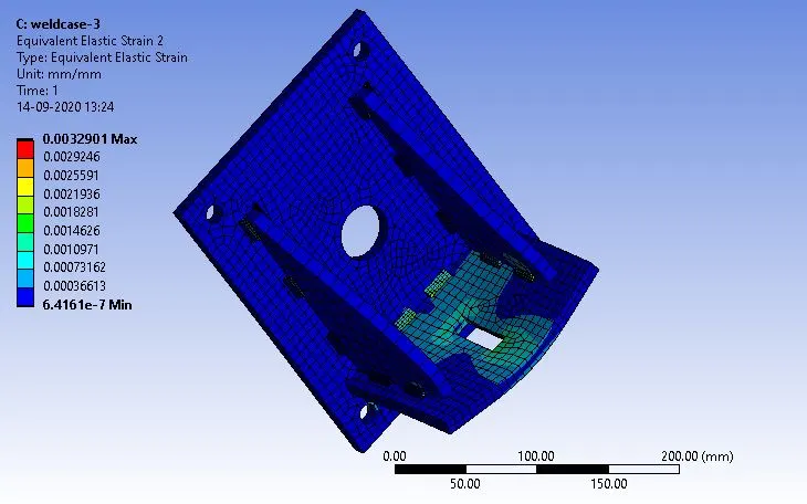
Equivalent strain experienced by the setup.
Equivalent strain experienced by the Ribs:
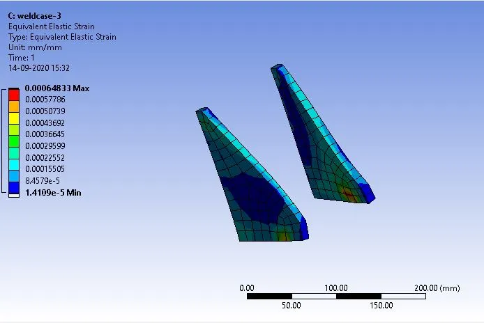
Equivalent strain experienced by the setup:
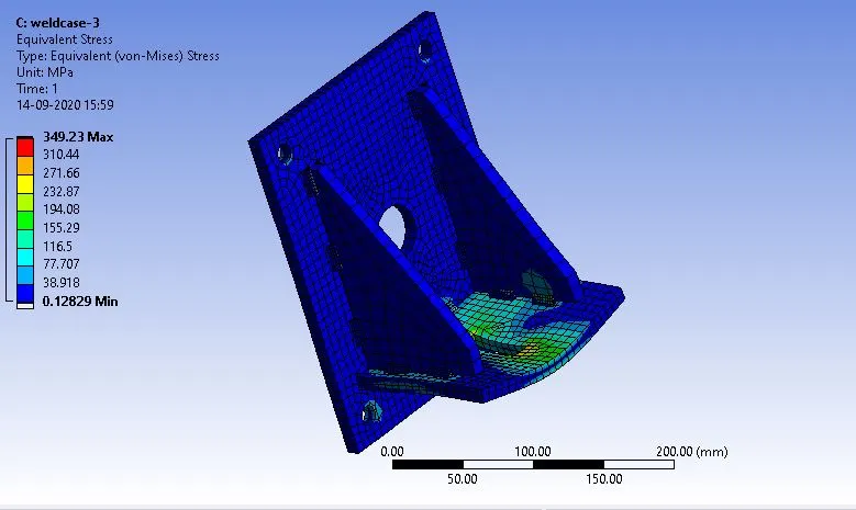
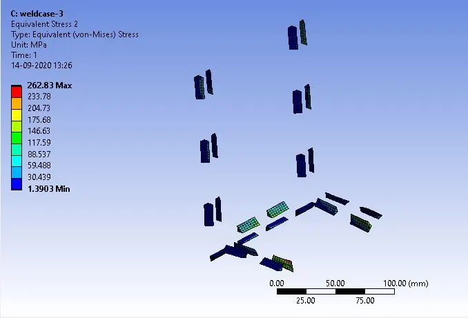
The weld joint that experiences the highest equivalent stress.
Animation for the Directional Deformation experienced by the setup.
Conclusion:
| Sr.No | Directional deformation | Equivalent strain | Equivalent stress |
| Case-1 | 0.340 | 0.0017 | 339.33 |
| Case-2 | 0.422 | 0.0018 | 351.49 |
| Case-3 | 0.386 | 0.0032 | 349.23 |
We can conclude that from the above result
The strain on the bronze cast material used the brazing weld joint has the maximum equivalent strain among the other materials of the case-3.
The directional deformation in the y-axis is high in the case of Aluminium material of the case-2.
The maximum Equivalent stress is also high in the case of Aluminium material of the case-2.