Project 1 : CFD Meshing for Tesla Cyber Truck
Aim:
Check and correct all geometrical flaws for the provided tesla cybertruck model, and then assign suitable PIDs and then requried Target length and element for the mesh Quality criterion.
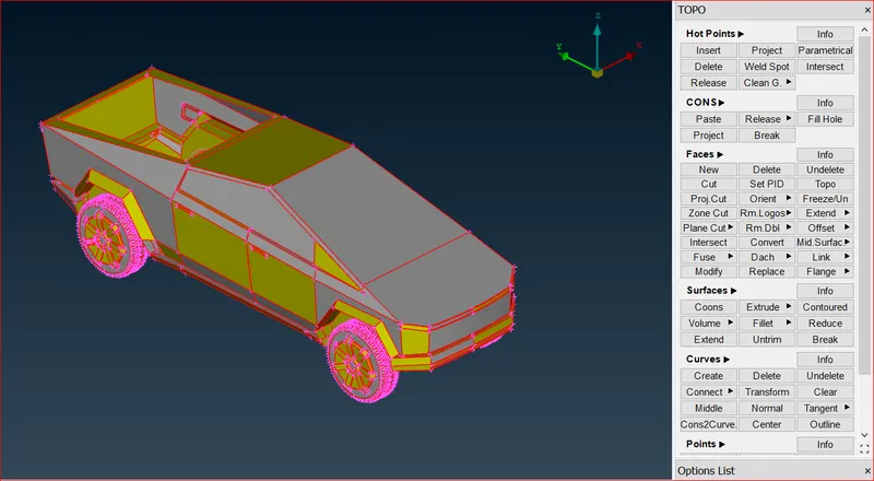
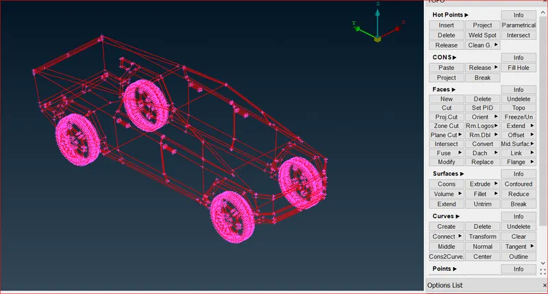
After using the topo tool in the geometry, we can see that all single cons have been transformed to double cons.
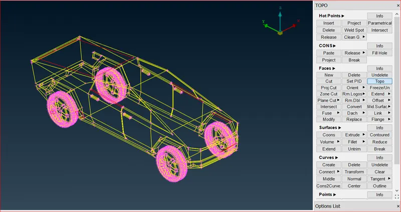
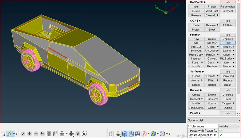
Thus, we can use ANSA's built-in geometry check.
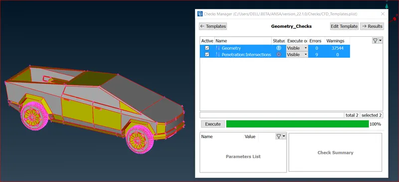
Select both geometry and Intersection and click execute.Following execution, we can identify every geometry mistake, allowing us to address each one individually.

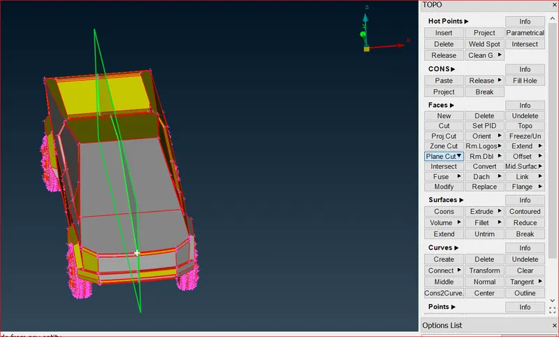
Use the plane cut on geometry so that it will be divided in two equal parts as shown below.
Use the face delete option on geometry so that you can remove the other part of the geometry which has been divided.
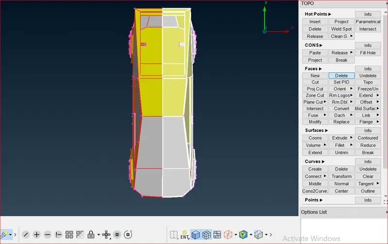
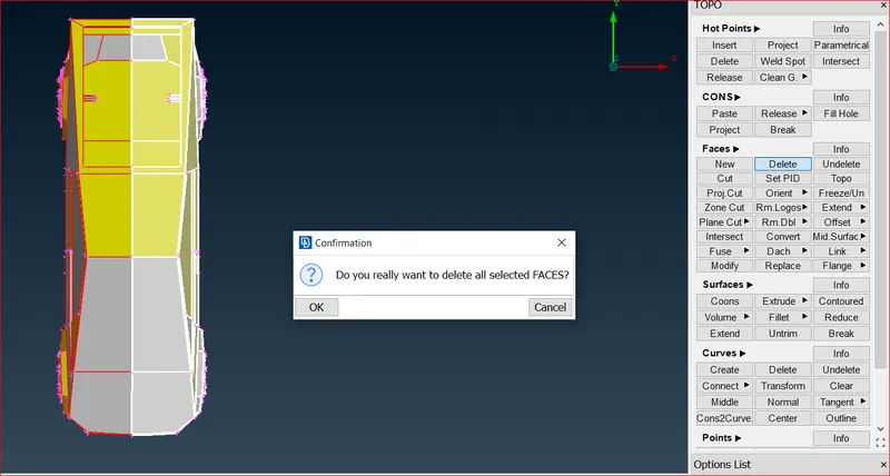
Eliminate half geometry. Always delete the side with the least amount of effort required to correct geometry as shown below.
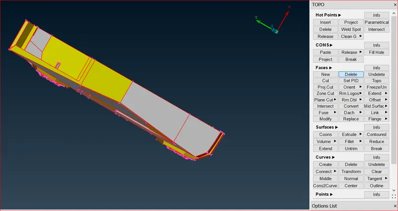
so to create faces we have to go for Topo - faces - New
- planer
- fitted
- coons
- existing
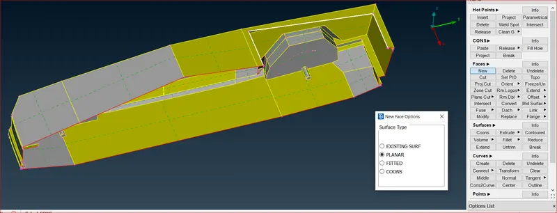
we can use Fill hole option.We will choose these option according to the accuracy of the outcomes.To Fill these holes select option then select the cons (we can select entities by one by one or can select one loop by loop select in below left)then middle click and select surface.on the curved surface we will use coons or fitted(because planer can not fill hole on curved surface properly).
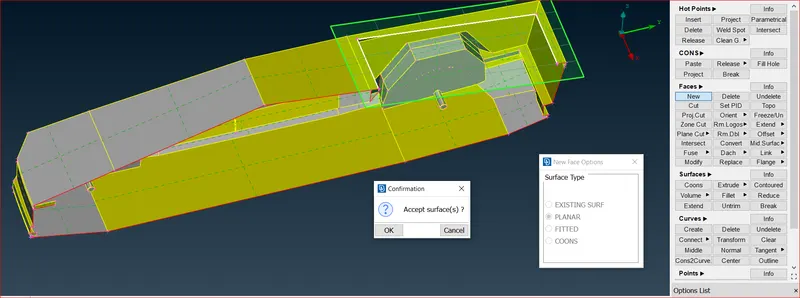
After using the face option then we can check for the intersection error in the geometry as shown below.
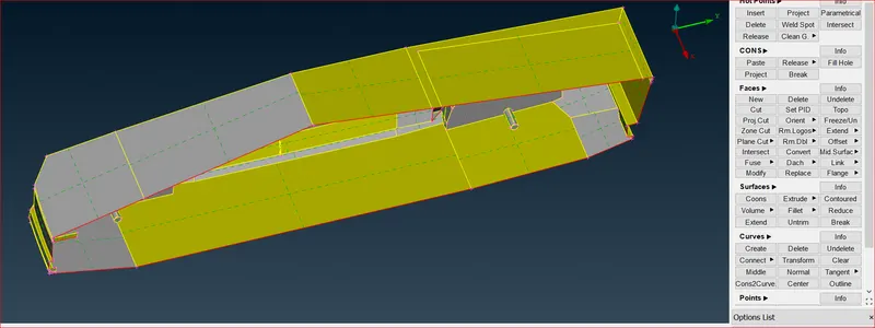
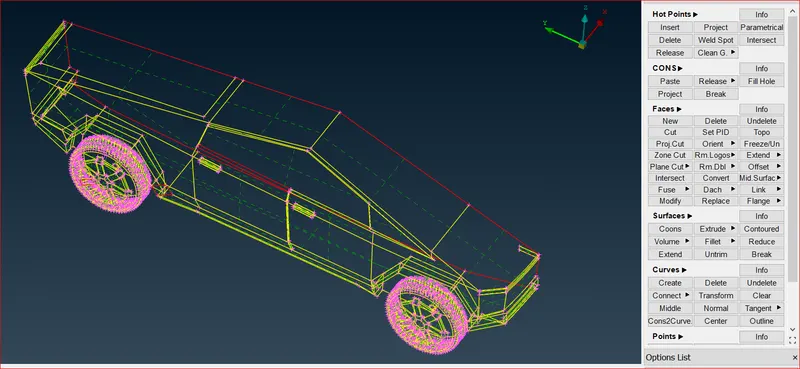
we can use Fill hole option.We will choose these option according to the accuracy of the outcomes.To Fill these holes select option then select the cons (we can select entities by one by one or can select one loop by loop select in below left)then middle click and select surface.on the curved surface we will use coons or fitted(because planer can not fill hole on curved surface properly).
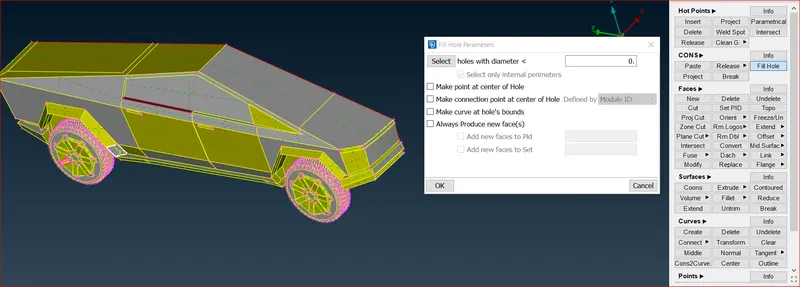
we can use Fill hole option.We will choose these option according to the accuracy of the outcomes.To Fill these holes select option then select the cons (we can select entities by one by one or can select one loop by loop select in below left)then middle click and select surface.on the curved surface we will use coons or fitted(because planer can not fill hole on curved surface properly).
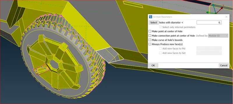
After using the face option then we can check for the intersection error in the geometry as shown below.
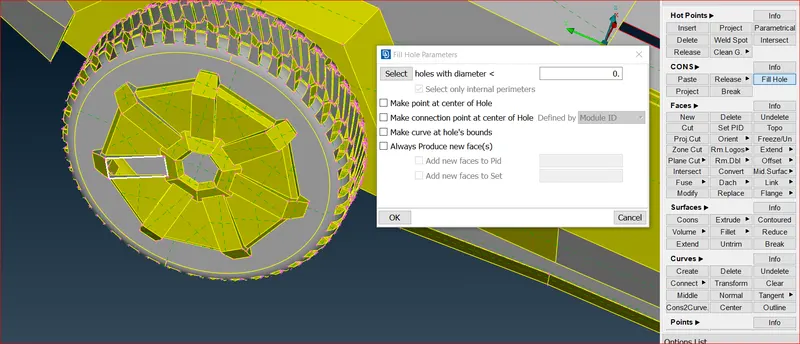
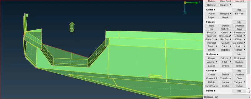
We can see one of the face is missing at the car window and we need use fill hole for that.
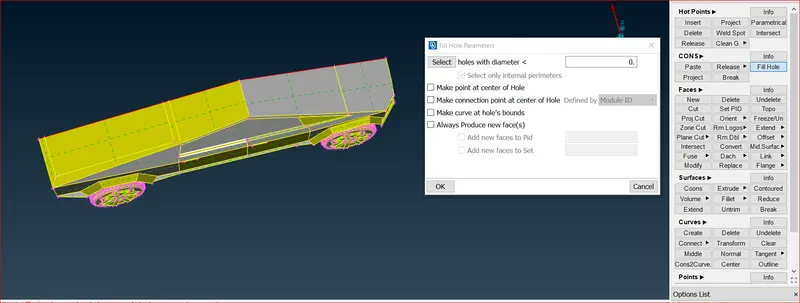
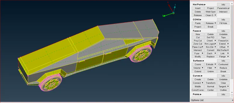
Select both geometry and Intersection and click execute.Following execution, we can identify every geometry mistake, allowing us to address each one individually.
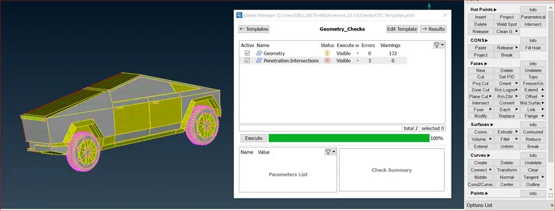
Now we can see the intersection errors in the geometry we need to clear them
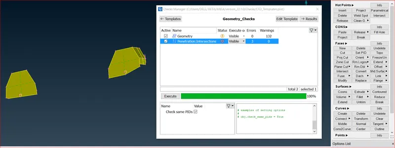
We can see the intersection faces between the tries and axle of the wheel so we can directly delete the face which are overlapping with each other.
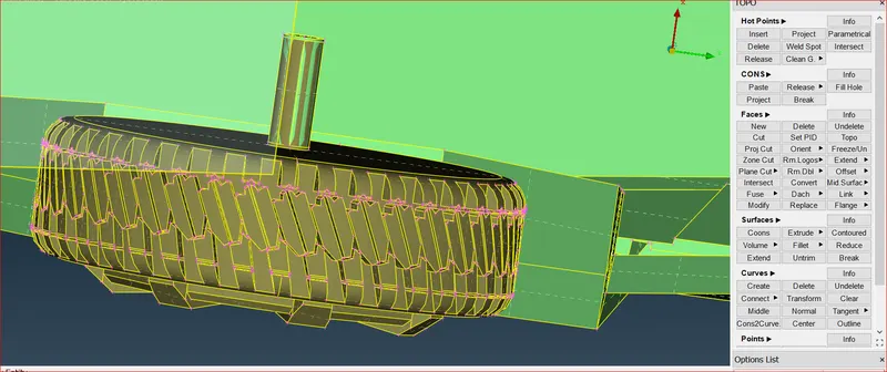
We can directly the axle which is directly overlapping with the face of wheel axle
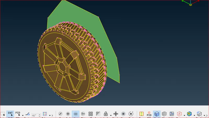
We have cleared all the intersection faces between the tries and axle of the wheel.
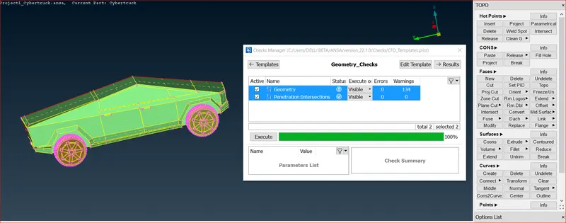
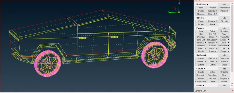
Before assigning the PID for the boundary the image is shown as below
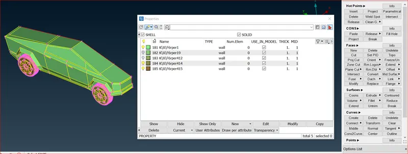
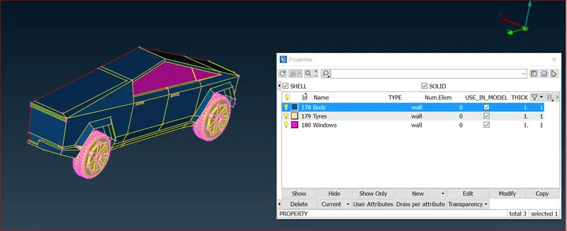
Using PIDs, each individual part is assigned a PID based on its usage.
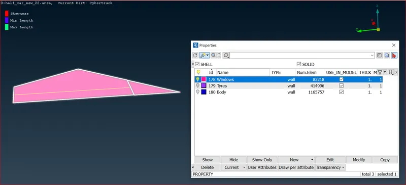
Windows:
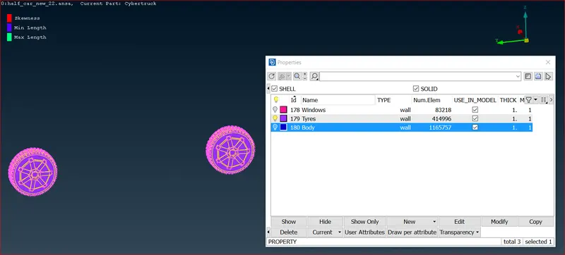
Tyres:
Body:
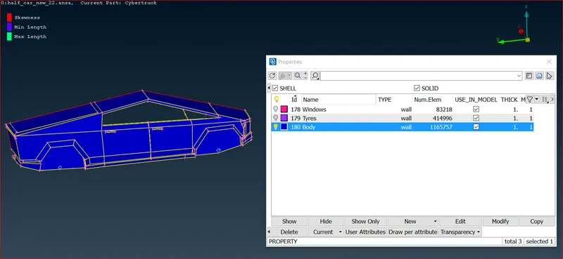
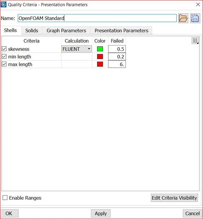
Before outputting the model it is recommended that you clear the database from any empty or unused grids, PIDs, etc, using the function Compress.
The final view in PID mode is given below as a clean model.
Window:The dimensions are as stated above.
In mesh - spacing - Auto CFD -peremeter then select the geometry and middle click and then select the max length as 5mm and minimum length as 3mm and ok, same do for macros.
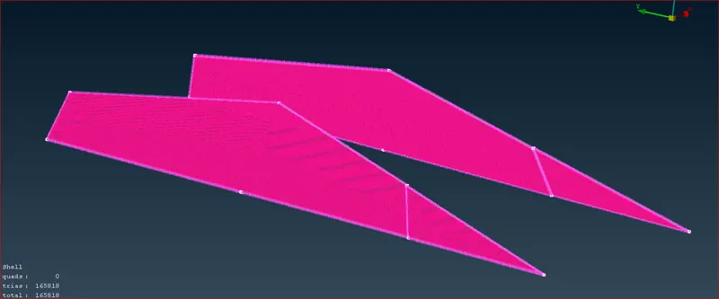
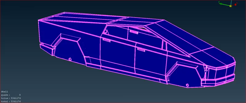
Body: The dimensions are as stated above.
In mesh - spacing - Auto CFD -peremeter then select the geometry and middle click and then select the max length as 4mm and minimum length as 2mm and ok, same do for macros.
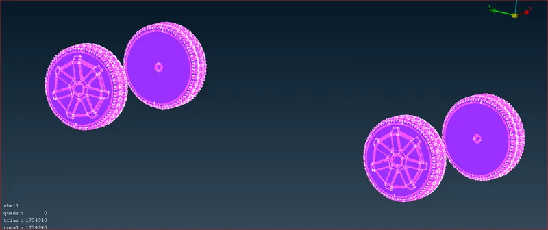
Wheels: The dimensions are as stated above.
In mesh - spacing - Auto CFD -peremeter then select the geometry and middle click and then select the max length as 5mm and minimum length as 3mm and ok, same do for macros.
Using the Transform command, the half-model is reproduced on the other side with the same mesh and PID.
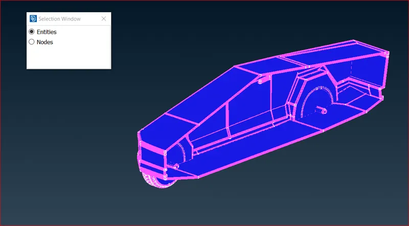
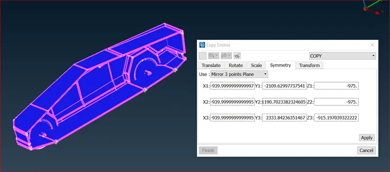
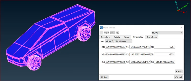
Using the Transform command, the half-model is reproduced on the other side and click on Apply and Finish.
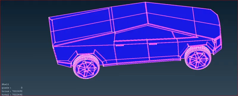
Total Tesla Truck body.
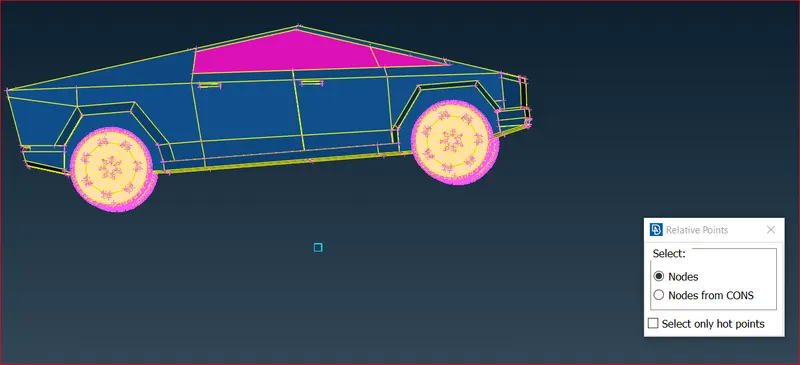
Bottom face
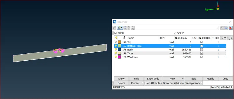
Top face
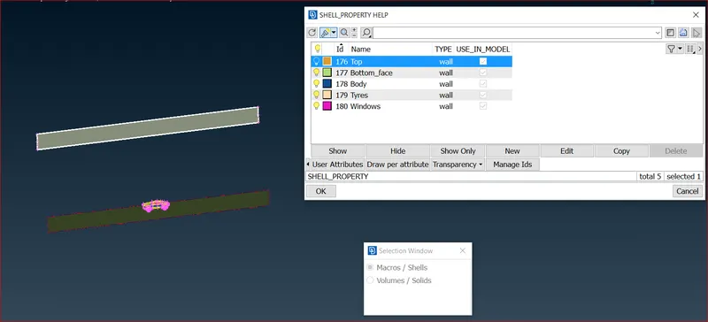 \
\
Rear Side Face
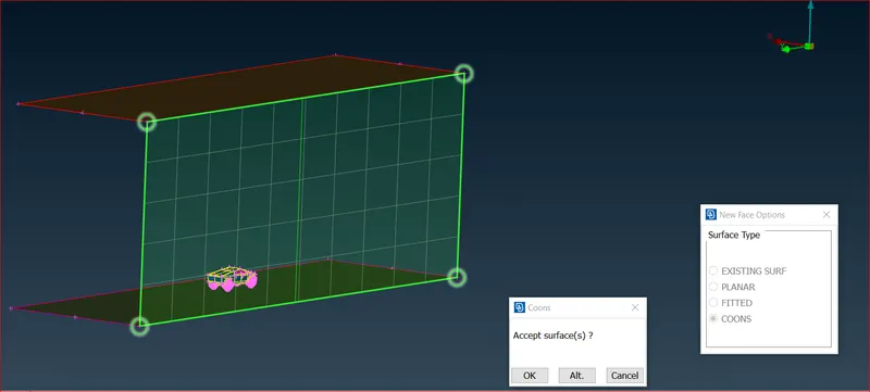
Front Side face
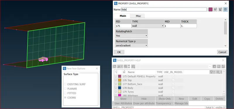
In and Out faces of the enclosure
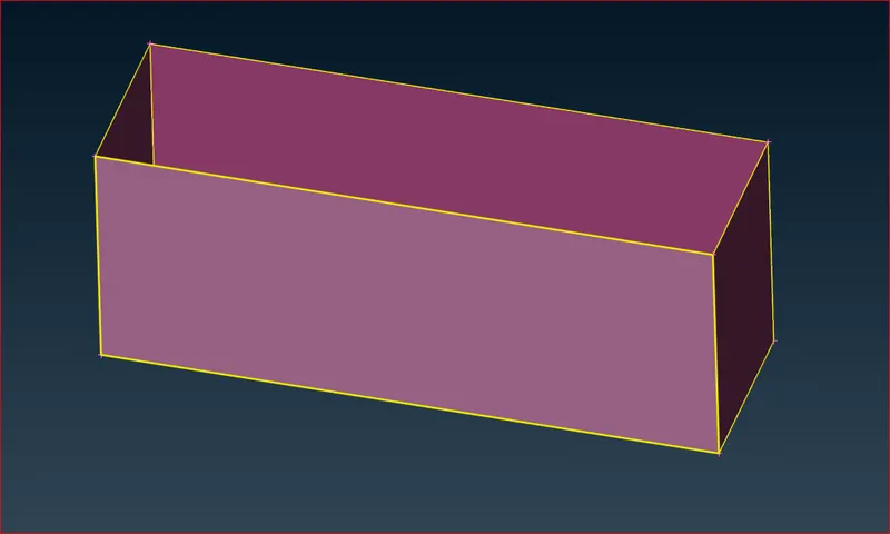
Total Enclosure
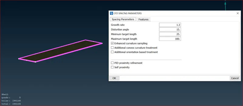
Bottom face
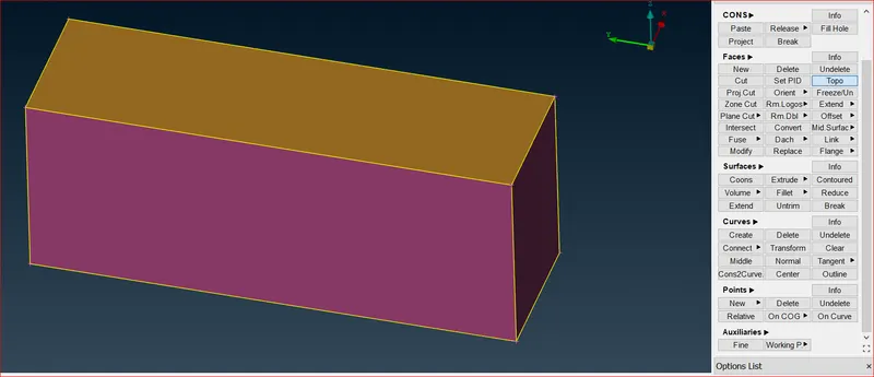
Top face
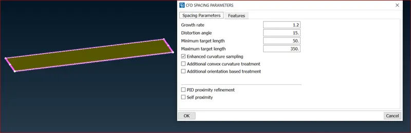
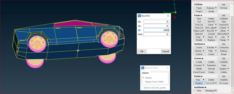
To link the two surfcae with various meshes, the vertical cons of the tunnel must be given a variable mesh that starts at 50 mm at the bottom and ends at 350 mm at the top, therefore the spacing input technique is used. The various points are also shown at the conclusion.
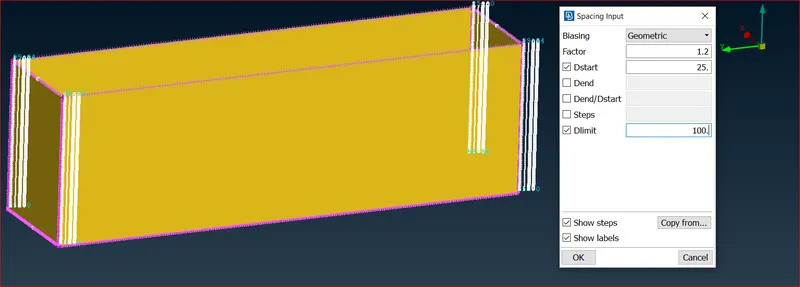
Following the meshing of the wind tunnel surfaces, it is evident that a range of meshes are accessible on the vertical surfaces.
Sufrace mesh for the Tesla Truck
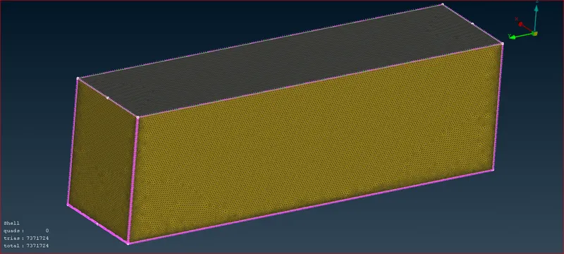
Following this phase, the final meshing should be done. However, due to system restrictions this work is unable to proceed.
CONCLUSION:
Working on the Tesla Truck model provided insight into the many meshing methods available in ANSA.
- Geometry cleaning and surface meshing were thoroughly studied. Problems solved enhanced comprehension of tools and how to create a wind tunnel using points and curves, as well as how to utilise the curve tool.
- Modelling wind tunnel dimensions, such as what measurements to provide dependent on model size. and when numerous PIDs with different mesh lengths are close to one another.
Link for the volume mesh file :
https://drive.google.com/drive/folders/1J8jsk5iql1kIvlopC_RzPxFw9P8P0wio
Note: This file upload in the above link is only upto surface mesh