Rolling operation Analysis using Ansys Structural Module
Aim :
Structural analysis was carried out to determine the behavior of a workpiece made of copper by measuring the stress equivalent, deformation in a specific direction, and plastic strain.
Introduction:
In metalworking, rolling is a metal forming process in which metal stock is passed through one or more pairs of rolls to reduce the thickness and to make the thickness uniform. The concept is similar to the rolling of dough. Rolling is classified according to the temperature of the metal rolled. If the temperature of the metal is above its recrystallization temperature, then the process is known as hot rolling.
If the temperature of the metal is below its recrystallization temperature, the process is known as cold rolling. In terms of usage, hot rolling processes more tonnage than any other manufacturing process, and cold rolling processes the most tonnage out of all cold working processes.
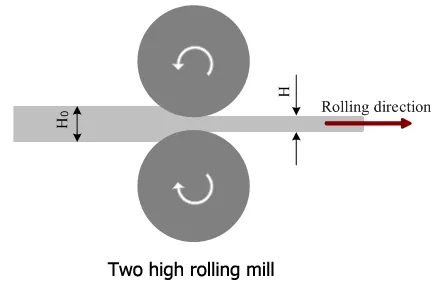
Roll stands holding pairs of rolls are grouped together into rolling mills that can quickly process metal, typical steel into products such as structural steel (I-beams, angle stock, channel stock), Bar stock, and rails. Most steel mills have rolling mill divisions that convert the semi-finished casting products into finished products.
Geometry :
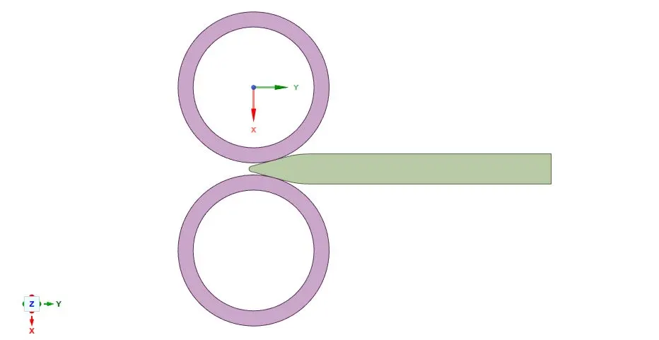
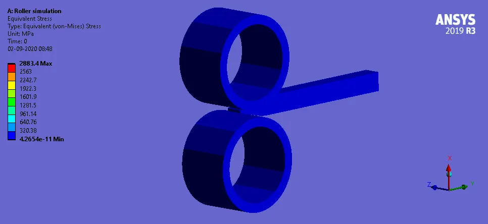
The rollers with a diameter of 50 mm are pushed by a rectangular workpiece of 100 * 9 * 10 mm. To ensure smooth initial movement, the front side of the component is tapered. The following geometry is shown for the analysis
Material :
Both the rollers and defined with structural steel as the material.
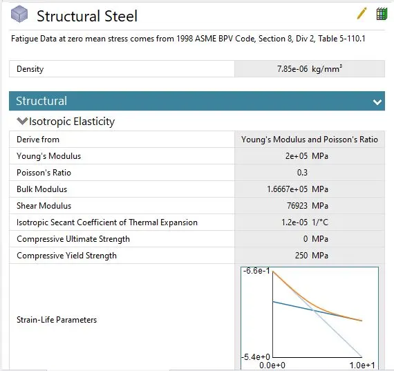
Structural steel is a category of steel construction material that is produced with a particular cross-section or shape, and some specified values of strength and chemical composition. Structural steel composition, strength, size, shape, strength, and storage are controlled in most advanced countries. The word structural steel includes a broad variety of low carbon and manganese steels that are used in great numbers for civil and marine engineering applications.
Copper was assigned for the work-piece.
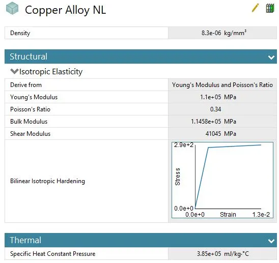
Copper alloys are metal alloys that have copper as their principal component. They have high resistance against corrosion. The best known traditional types are bronze, where tin is a significant addition, and brass, using zinc.
Contacts:
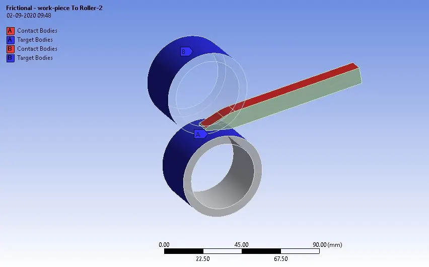
The relation between the rollers and the segment is modeled as a frictional contact with a friction coefficient of 0.2. Augment Lagrange with specified standard stiffness factor of 0.1, updating each iteration to carefully model element propagation. The rollers are also used for setting up.
Joints:
Rollers are provided with a cylinder joint connected to the ground due to which the motion in x and y-direction can be constrained.
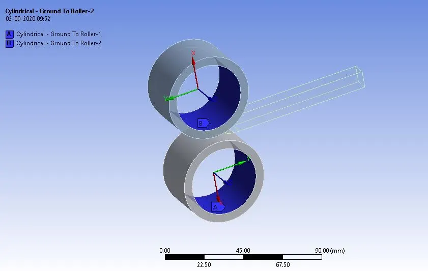
since the displacement of the roller in the z-direction is not constrained a planar joint was defined on the side face of the roller. This ensures that there will not be any minute displacement in the z-direction. Hence there exist only the rotation of the rollers
Analytical settings:
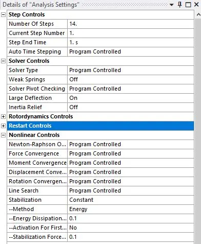
The analysis was carried out in 14 steps and to account for large deformations, the large deflection was enabled. To provided a stabilizing force for converging against instability due to non-linearities, stabilizing energy is switched on with an energy dissipation ratio of 0.1 which is recommended for bending or extrusion application.
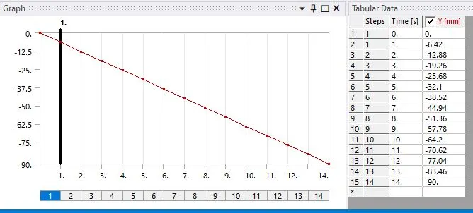
The workpiece is provided with the displacement condition that varies almost linearly throughout the time step. It is defined in such a way that the workpiece will be displaced 90mm at the end of the final time step.
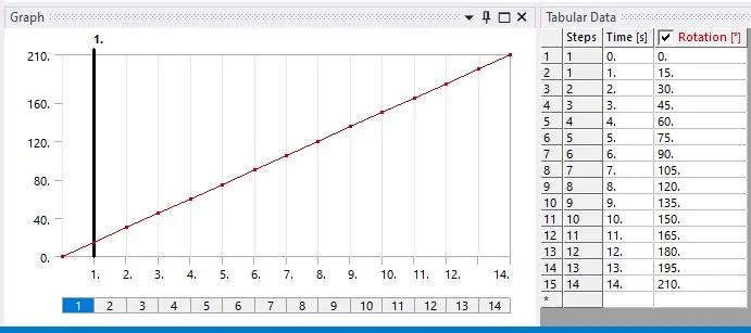
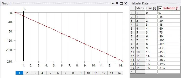
Rotational boundary condition was defined for both the cylindrical joints in which the rotation angle varies almost nearly from 0 to 210 degrees.
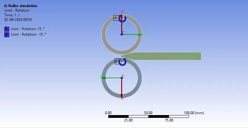
Also, it is ensured that both the rollers will be rotating in the opposite direction.
Roller-1
Roller-2
Results :
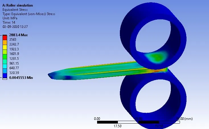
Equivalent stress for the whole setup.
The max and min values for the Equivalent stress
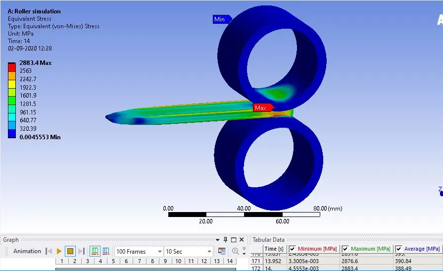
From the above results, an increasing trend in the magnitude of equivalent stress is observed which later becomes asymptotic. Some turbulence behavior in the starting steps of simulation is also to observe d in the graph between max equivalent stress and time steps.
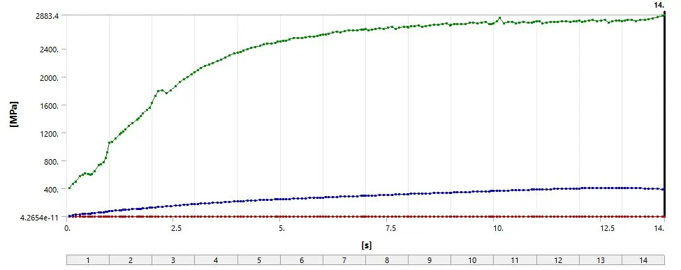
The initial increase in the magnitude of Equivalent stress is attributed to the fact that there is an increase in the amount of material at the beginning which is compressed by the distance between the rollers.
This allows more material to resist deformation and hence high-stress values develop in addition to the sliding contact status between the roller workpiece interfaces during initial steps allows the turbulence behavior in the beginning and leads to unstable high-stress growth. Subsequently, this structure becomes uniform and thus no more sudden changes occur but due to the accumulation of deformed material on the uncompressed size, the magnitude of stress produced increases further but in the later stages this accumulation becomes constant.
Animation for the Equivalent stress for the whole setup.
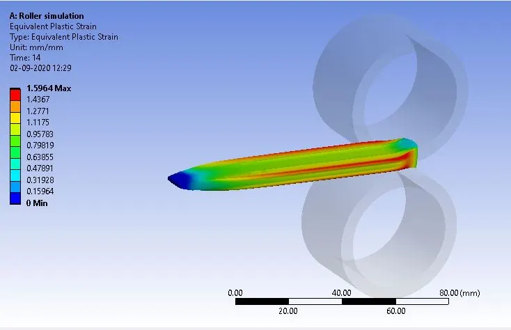
Equivalent Plastic strain for the workpiece:
Max and Min values for the Equivalent Plastic strain for the workpiece:
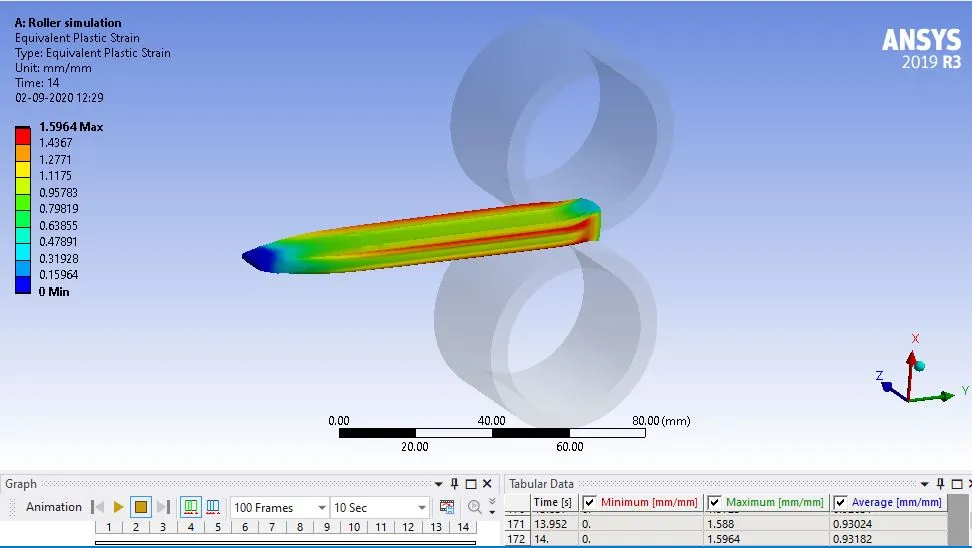
Resutls showed a similar behavior of development of Equivalent Plastic strain as in the case of Equivalent stress.
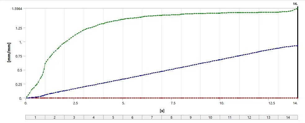
With the increases in the pressure between the gap more plastic deformation occurs as the same observed in the graph.
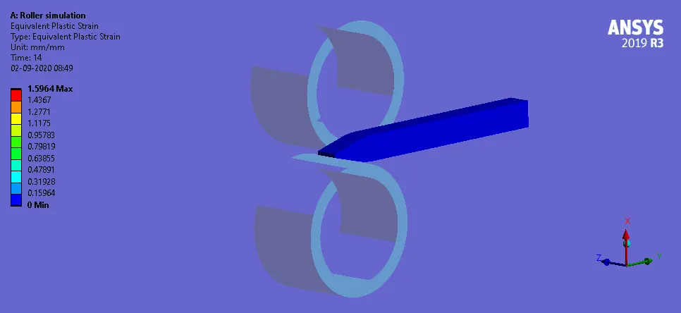
Animation for Equivalent Plastic strain for the workpiece.
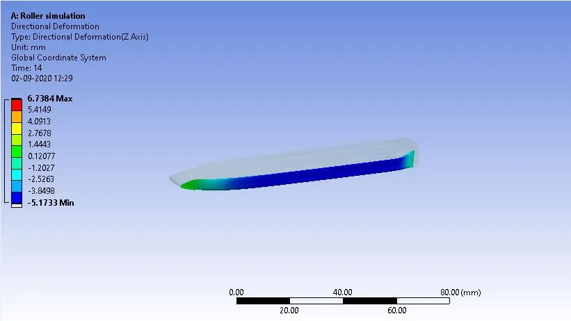
Directional Deformation in the Z-axis for the workpiece.
Max and Min values for the Directional Deformation in the Z-axis for the workpiece.
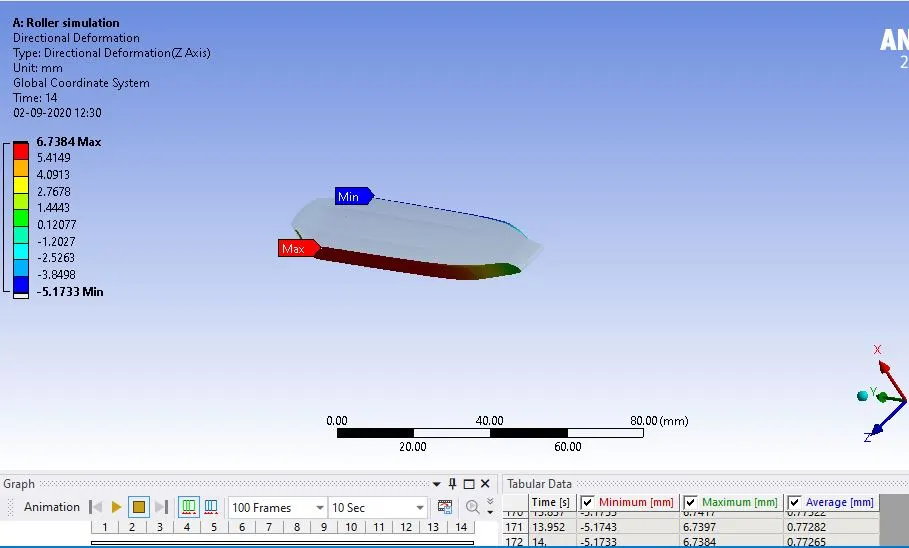
Results showed the informational increases in the width of the workpiece by a magnitude of approx 6.73 mm both sides.
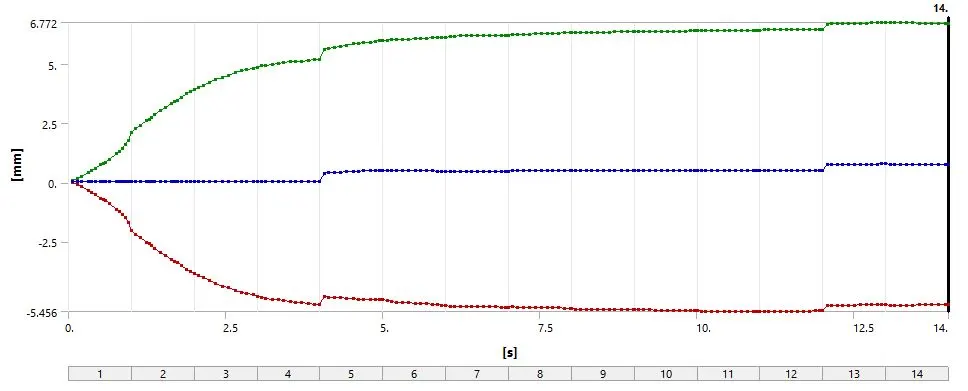
Since the workpiece is added to the gap of rotating rollers, the only space left to deform due to rolling operating pressure is to deform the width wisely, although it is also possible in the longitudinal direction, however, the workpiece is pushed in that direction such that only a tiny amount of deformation occurs in the longitudinal direction.
Animation for Directional Deformation in the Z-axis for the workpiece.
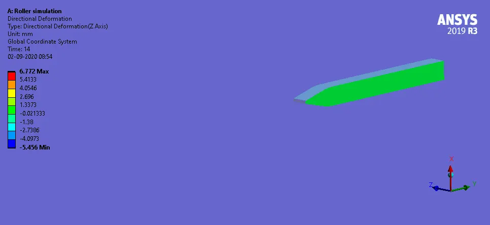
Prove that the workpiece has displaced by 90mm.
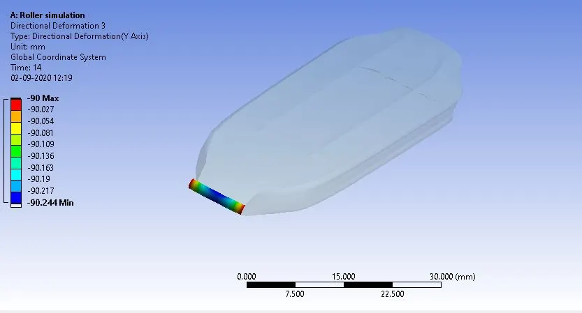
Max and Min values for the Directional deformation in Y-axis
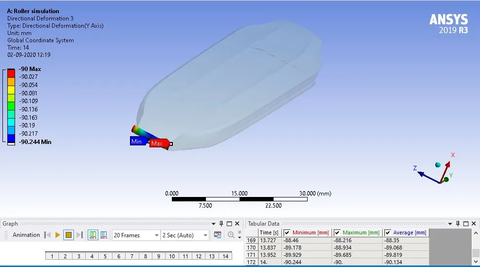
The result shows the directional deformation of the workpiece tip along the lengthwise direction.
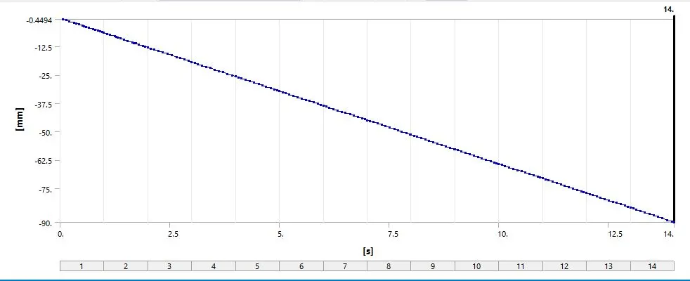
It is observed that the way in which deformation occurs is almost exactly similar to the boundary displacement condition hence confirming the displacement of the workpiece by 90mm.
Animation for the Directional deformation in Y-axis
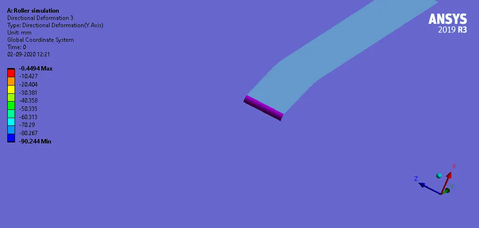
Conclusion:
It has been proven by the directional deformation in the edge's y-direction that the tool moves 90 mm and stress, strain and directional deformation have also been demonstrated.
- Mandalsankhadipcan u please share me the wpbz file for ansys