Week 4 Challenge : CFD Meshing for BMW car
Aim:
To check for geometrical errors and create appropriate volumes for the given model, create and assign
PIDs. Surface meshing with the given target lengths according to PIDs.
- Body - 3 mm
- Lights - 4 mm
- Grills - 1 mm
- Rims and Tyres - 2 mm
- Optical Rear view mirror - 2 mm
- Window - 2 mm
- Silencer - 3 mm
- Logo - 1 mm
Learning Outcomes:
- Geometry cleanup
- Surface meshing
- Volume meshing
Procedure:
The available 3D model of the BMW automobile is cleaned and meshes are created for external CFD simulation in this project. Below is a step-by-step process diagram.The raw model to be treated is shown in the image below. As can be observed, the model has a great deal of defects and drawbacks that need to be addressed.
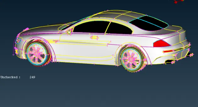
Deeper inspection reveals that numerous curves have been smoothed out because they are not always clear.
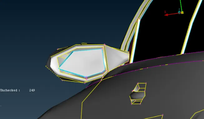
we have used the mesh parametters to refine the geometry as shown below.
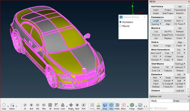
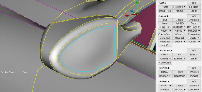
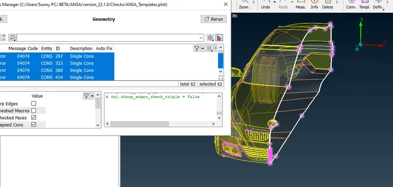
In display mode, only single cons are kept available; the quantity of single cons is clearly seen in the image below.
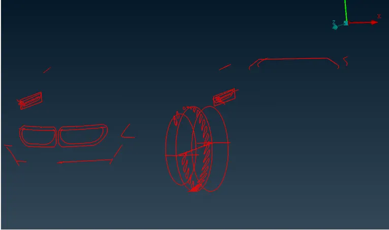
A triple cons check is also carried out to ascertain how many of these cons are included in the model.
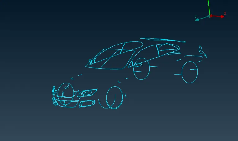
Due to symmetry, the entire car body is divided into two halves, only one of which is retained. Only this portion of the model needs to be altered, and the centre plane will then be used to recreate the model.
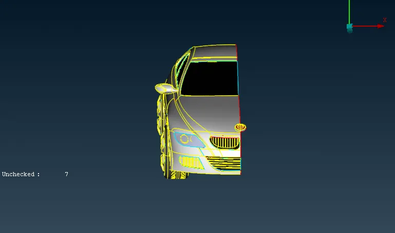
The single and triple disadvantages must all be eliminated. The headlamps and front grilles are initially left open. You can see a screenshot below.
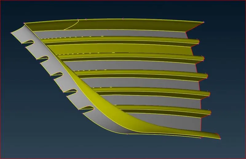
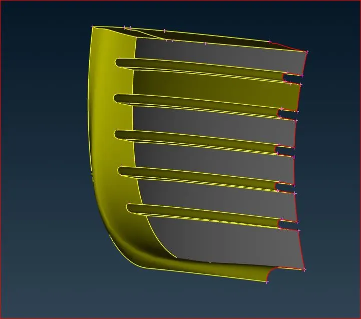
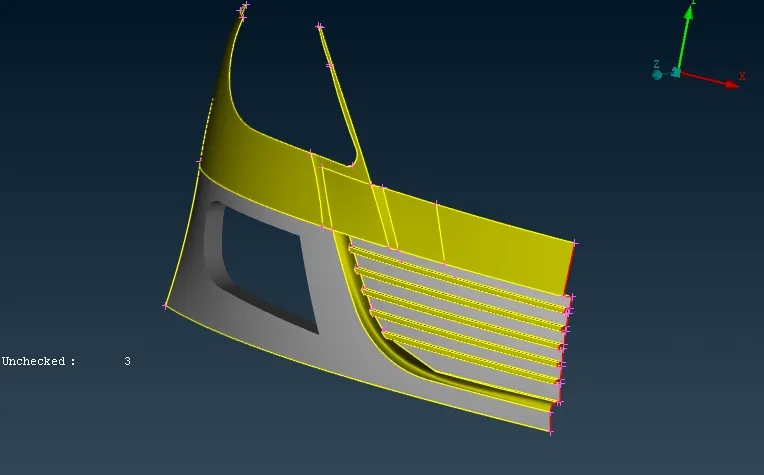
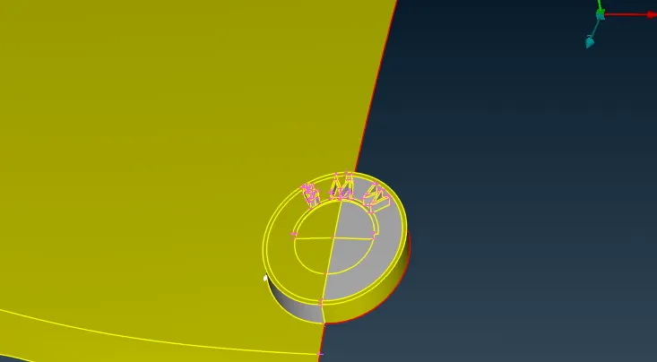
It also has to be topologically cleaned up the current logo.
Similar to this, several more components are cleaned individually and made free of single and triple defects. Rearview mirrors, exhaust systems, lights, and windows are some of the parts.
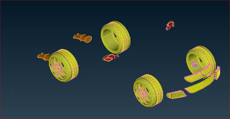
Finally the model with all the double cons except the center line is obtained.
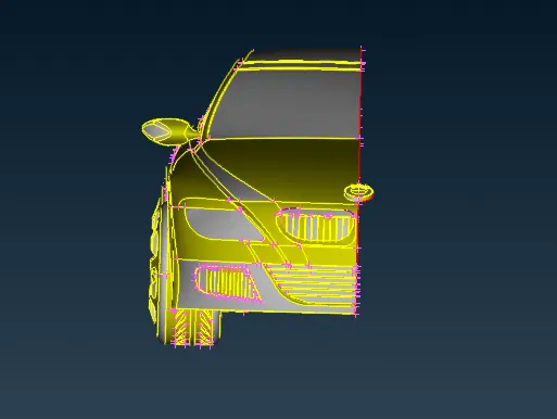
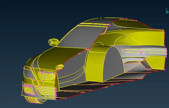
Geometry check is also made to ensure that there is no presence of single cons except the center line.
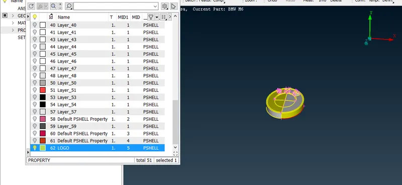
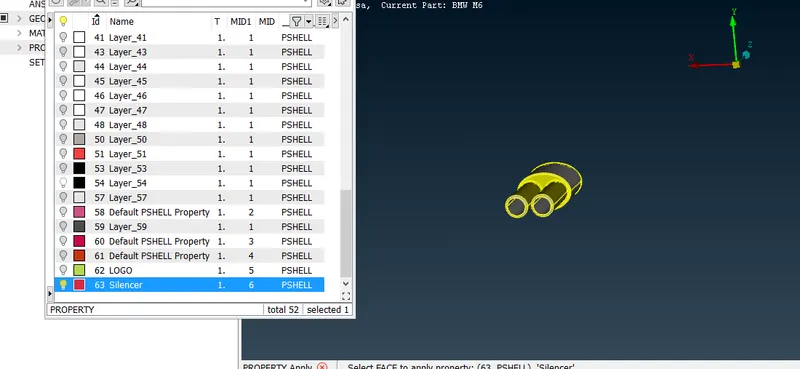
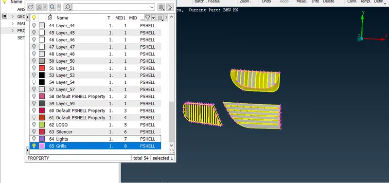
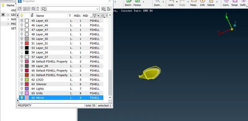
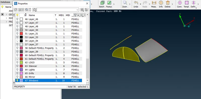
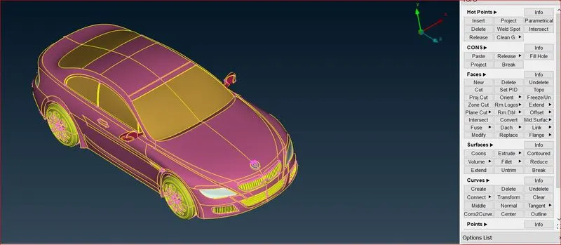
Applying PID's: Each of the specific part is given its PID as per use.
Logo
Silencer
Grills
Mirror
Windows
Rims and Tyres
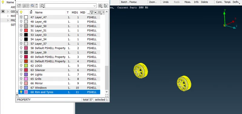
Body
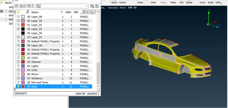
The final view with the PID mode can be seen as a clean model and is shown below.
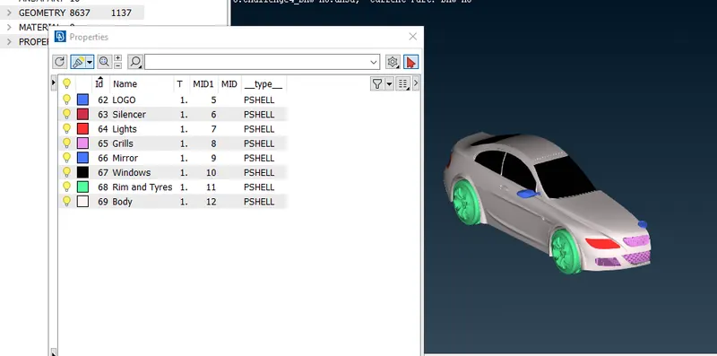
Each of the PID is meshed on surface with the given values.

Before outputting the model it is recommended that you clear the database from any empty or unused grids, PIDs, etc, using the function Compress.
Target lengths for the different parts of a model are as follow:
- Body - 3 mm
- Lights - 4 mm
- Grills - 1 mm
- Rims and Tyres - 2 mm
- Optical Rear view mirror - 2 mm
- Window - 2 mm
- Silencer - 3 mm
- Logo - 1 mm
Except All meshing is done with the same minimum and maximum lengths and other parameters.
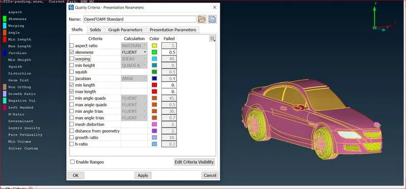
Logo and Grills : The dimensions are as stated above.
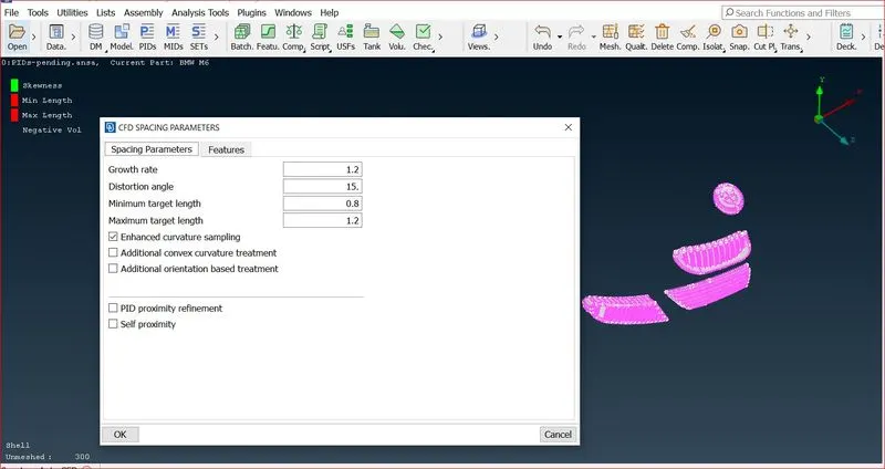
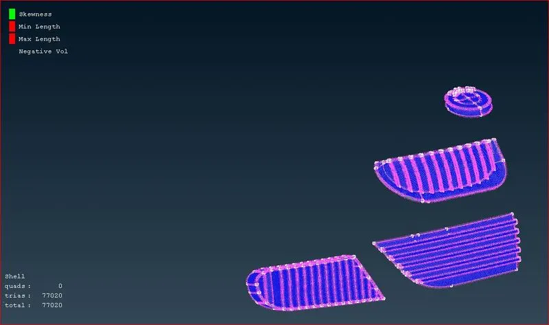
Tire and Rim and side Mirror,Windows : The dimensions are as stated above.
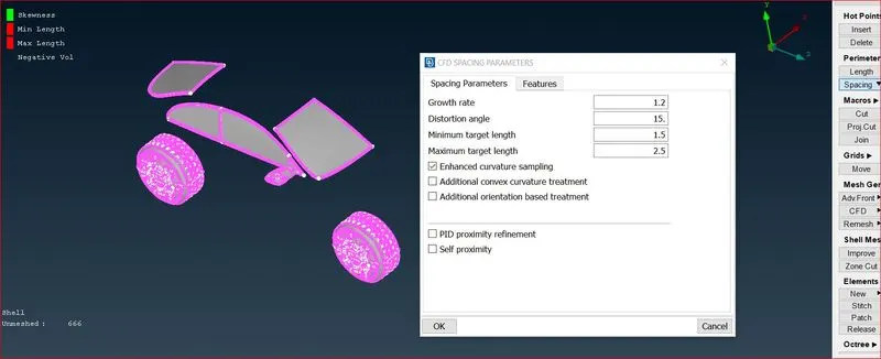
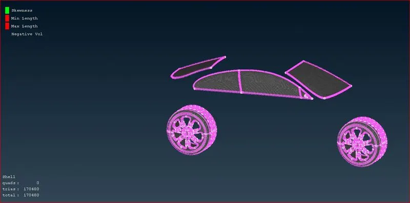
Body and Silencer: The dimensions are as stated above.
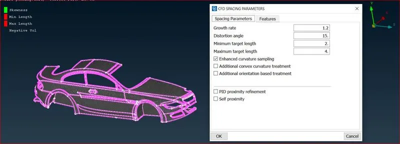
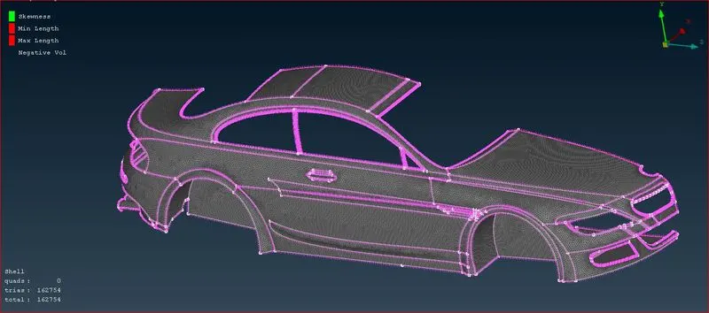
Various tools, including as Remesh, Paste, Move, Topo cleanup, etc., are used in between to clean up the errant meshes.
Complete assembly
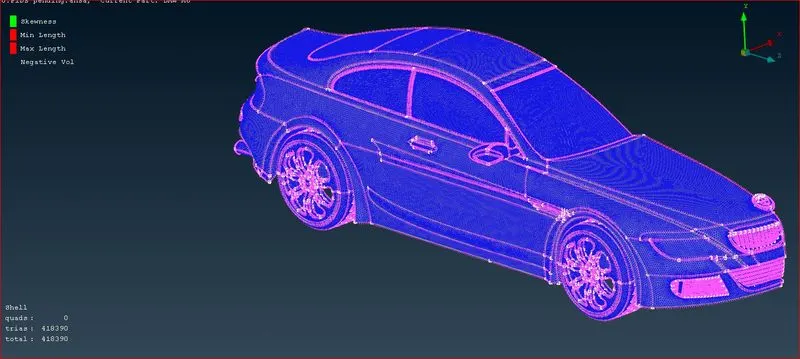
The half-model is now replicated on the other side with the same mesh and PID using the Transform command.
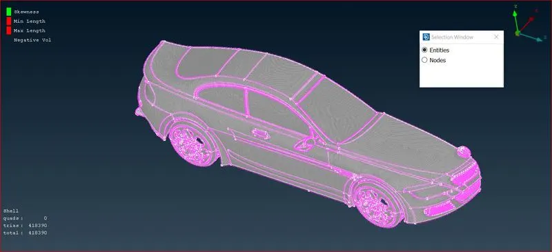
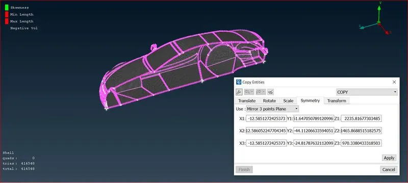
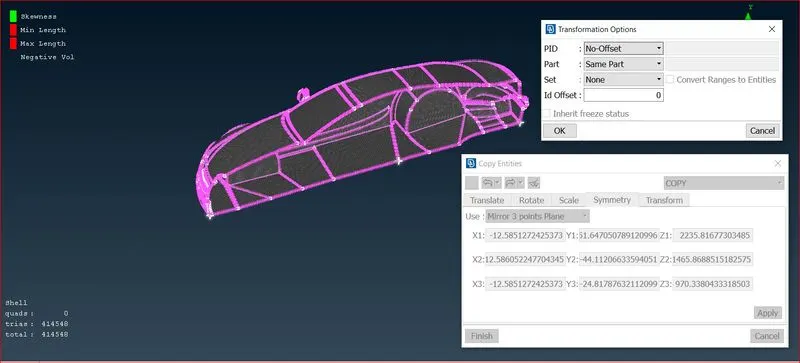
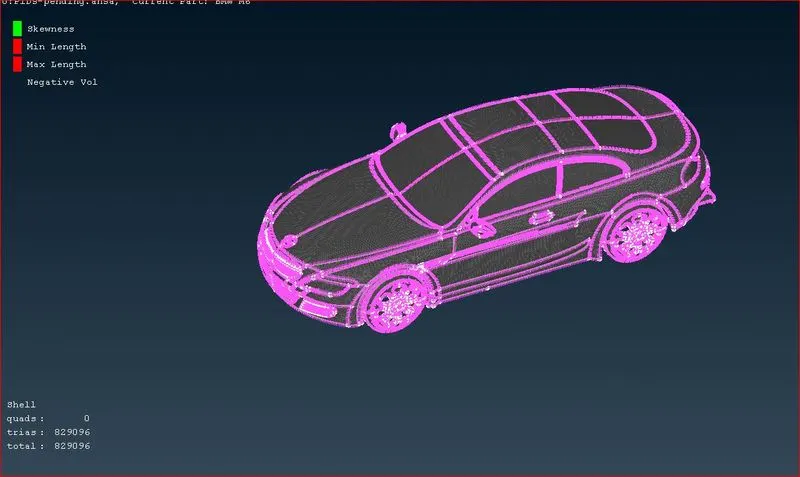
A entire car body with mesh and no off cons is displayed in the next image.
To ensure that there are no erroneous meshes, a mesh check is performed.
The dimensions of the automobile wind tunnel outside are displayed below.:
Wind Tunnel:
Total Length of Car = 1300 mm (X)
Length of wind tunnel from front end of car = 5200 mm (4x)
Length of wind tunnel from rear end of car = 7800 mm (6x)
Top Surface of wind tunnel from top of car = 3900 mm (3x)
Bottom Surface of wind tunnel from bottom of car = Nearer to the car wheels.
Left and Right surfaces from center of car = 1300 mm (3x)
Points are geenrated around the car so as to make new surfaces and then finally a wind tunnel.
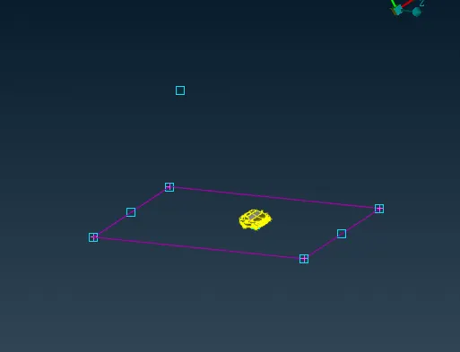
After the wind tunnel surfaces are made each of them is assigned specific PID's.
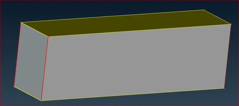
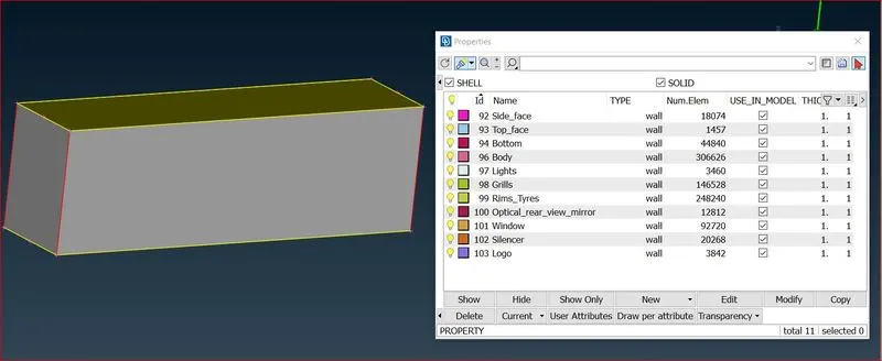
Due to the need for a fine mesh in the area where the car is, but other sides may have a larger mesh. The task calls for the upper wind tunnel surfcae to have a mesh size of 100 mm and the bottom surfcae to have a mesh size of 1 mm.
Bottom Face
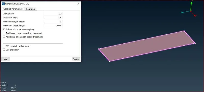
Top Face
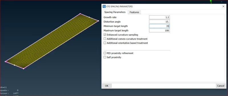
The vertical cons of the tunnel must be given a variable mesh that starts at 35 mm at the base and ends at 100 mm at the top in order to unite the two surfcae with different meshes, hence the spacing input method is utilised. The different points are also evident in the end.
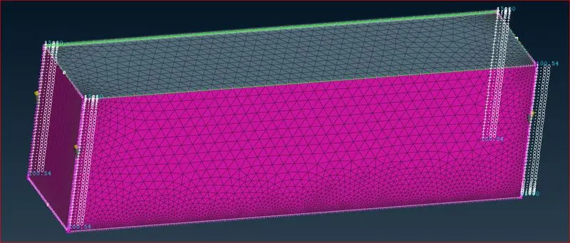
It is obvious that a variety of meshes are available on the vertical surfaces following the meshing of the wind tunnel surfaces.
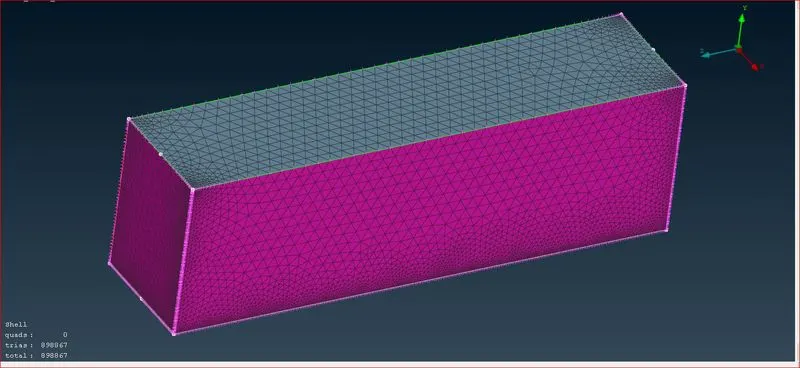
To perform the volumetric mesh, several available volumes are extracted. Only the first of the available volumes below is relevant for the volumetric mesh. Inside the vehicle, other quantities are excluded volumes.
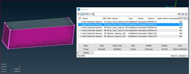
The final meshing is to begin after this step. But this effort cannot move forward due to system limitations and project constraints.
CONCLUSION:
Working on BMW model gave ideas about different meshing tools available in ANSA.
- learned geometry cleanup and surface meshing in great depth. Problems encountered improved understanding of tools.
- Learned how to design a wind tunnel using points and curves and how to use the curve tool.
- Learned about wind tunnel dimensions, such as what measurements to supply based on model size.
- Learned how to remesh when several PIDs with various mesh lengths are in close proximity to one another.
Link for the volume mesh file:
https://drive.google.com/drive/folders/1elLHtDUEfG1kUkh_m1pF_jEY7pShHuwl