Transient analysis on Long Piston With Cam mechanism
Aim:
To perform a Transient analysis on piston and cam mechanism for three different cases
To run the analysis with
Case:1 Contact between Cam and follower is Frictionless.
Case:2 Contact between Cam and follower is Frictionl with a coefficient of Friction with 0.1.
Case:3 Contact between Cam and follower is Frictionl with a coefficient of Friction with 0.2.
From the simulation results, we need to find Equivalent Stress, Directional Deformation, and Equivalent Elastic Strain and compare them for all the three cases. Give an inference as to why the results vary between cases.
Introduction:
Transient Analysis: It is a technique used to determine the response of a structure under the action of loads that are dependent on the time. It is also known as the time history analysis. This type of analysis is used to determine the time-varying displacement strain stress and forces in a structure as it responds to any transient loads. Here inertial or damping effects are important considerations.
In the following simulation motion of barrel cam and follower is analyzed for transient loads geometry consisting of a barrel, follower, and cam is pre-processed. Here rotation which is given as boundary condition to cam is acting as transient load. It constrains the followers to follow in the grooved portion and hence cause it to oscillate in the barrel. This whole motion is simulated in the following analysis for three different cases in which the frictional nature of the contacting surface is changed.
1.Frictionless contact
2.Frictionl with a coefficient of Friction with 0.1.
3.Frictionl with a coefficient of Friction with 0.2.
Case:1 Frictionless contact
Geometry:
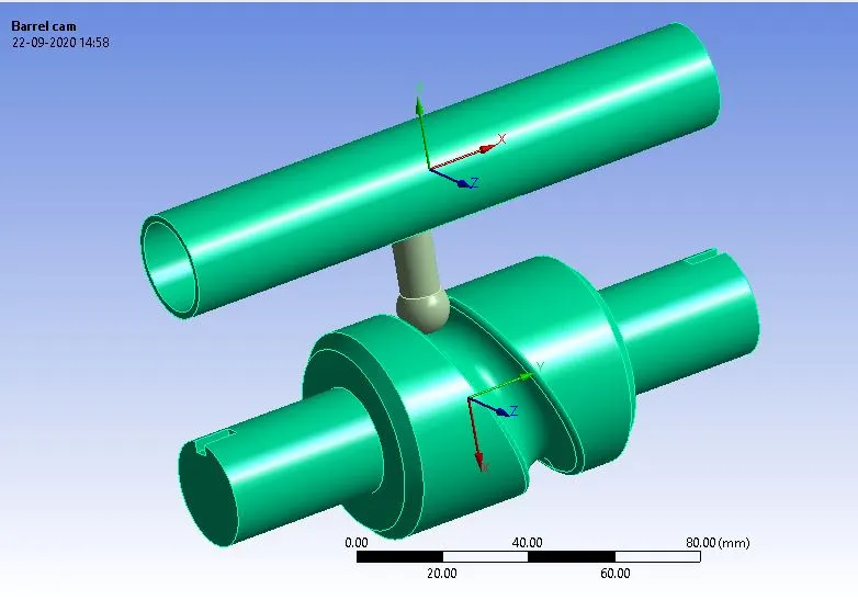
Then we have to import into ansys, import the model, and open it in space claim so that ansys will read it and checked for any errors.
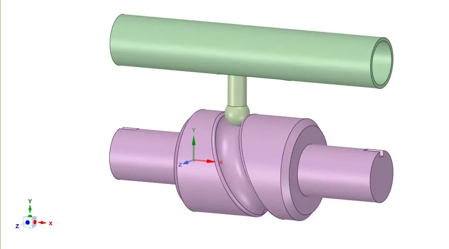
Rigid body in the model:
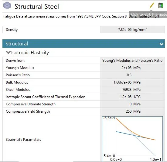
Materials:
Structural steel for the sphere:
Meshing:
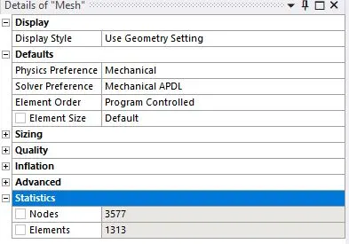
Components mesh with program-controlled mesh with a mesh element size of 6mm.
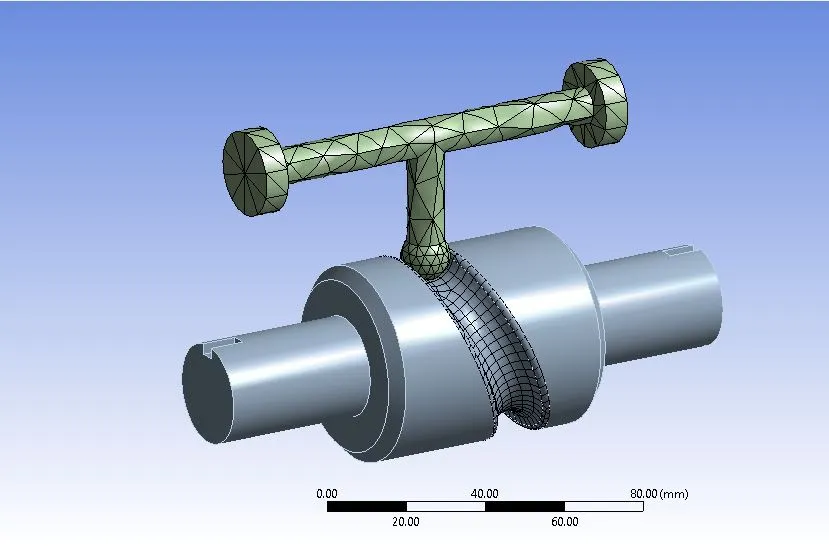
However, regions of particular interest i.e contacting surface between follower and cam is meshed using face sizing with a mesh element size of 3 mm.
The meshed model image and mesh metric graph can be seen below:
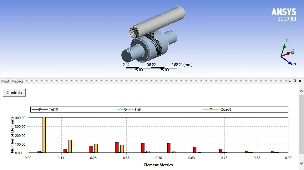
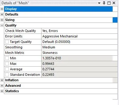
The mesh metric is utilized to identify the elements according to their quality using skewness. The quality of the mesh is acceptable as most of the elements lie within a high-quality range.
Setup:
Stiffness behavior.
Since our point of interest is on follower therefore in order to simplify the model rigid stiffness behavior is imposed on cam and barrel bodies. This will simplify our model by concentrating the body mass about its centroid.
Contacts:
1.In the first case Frictionless contact is established between all the contacting interfaces.
Frictionless contact between Barrel and cam follower:
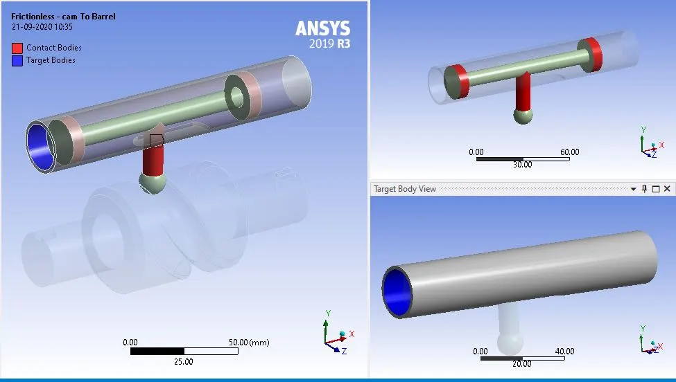
Frictionless contact between the cam follower and Cylinder cam:
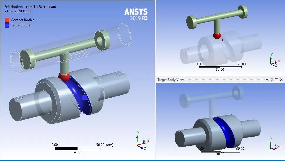
Details for the frictionless joint:
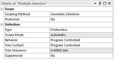
2.For the second case Frictional contact is established with 0.1 as the coefficient of friction.
Friction contact between Barrel and cam follower:
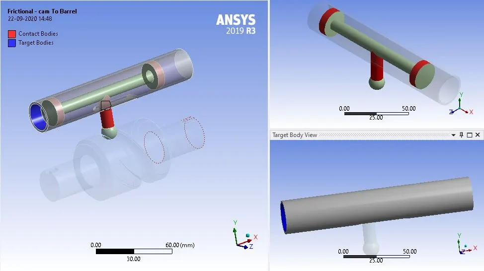
Friction contact between the cam follower and Cylinder cam:
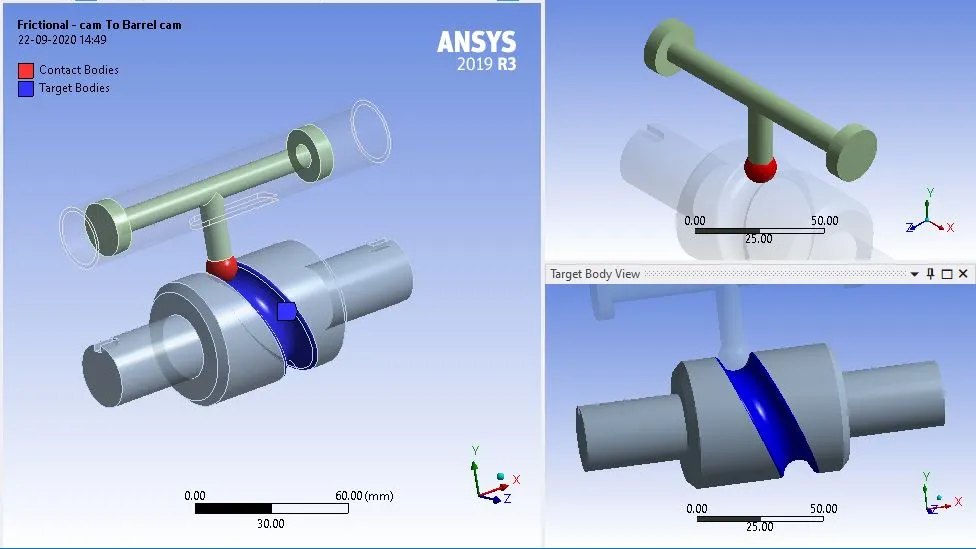
Details for the friction joint:
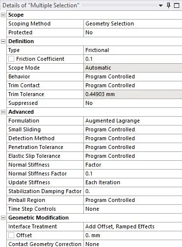
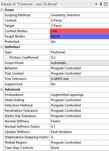
3.In the third case same Frictional contact is established but the value of the coefficient of friction is changed to 0.2.
Friction contact between Barrel and cam follower:
Friction contact between the cam follower and Cylinder cam:
Details for the friction joint:
Joint:
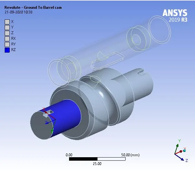
Revolute joint:
The revolute joint is assigned to the cylindrical cam relative to the ground hence allowing only axial rotation.
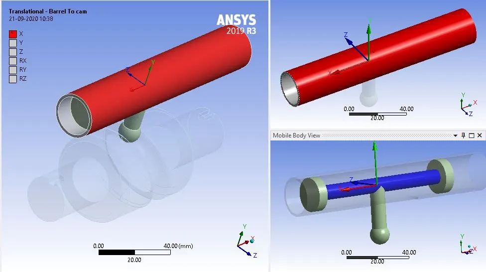
Translational joint:
The translational joint is assigned to the follower relative to the barrel so that the follower can move axially inside the barrel.
Fixed joint:
A fixed joint is given to the barrel relative to the ground in order to hold it steady
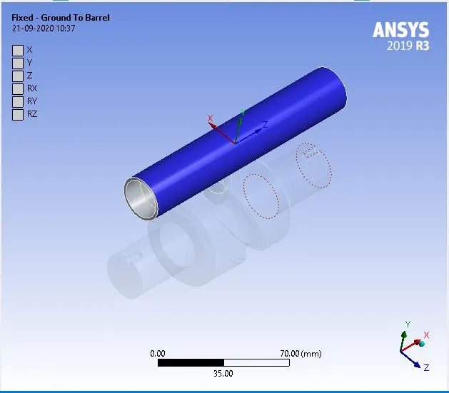
Boundary conditions:
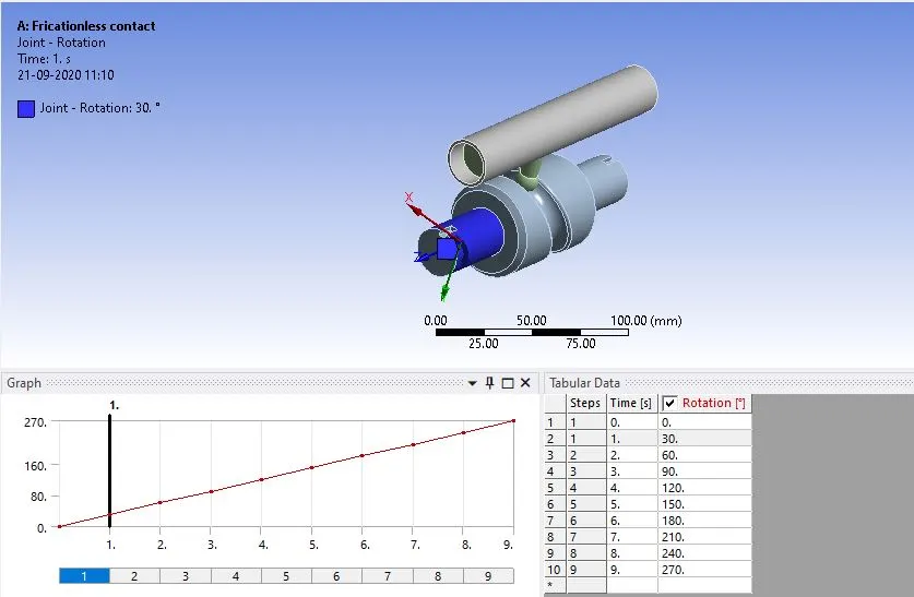
The boundary condition, time-dependent rotation is provided to the cylindrical cam.
Analysis setting:
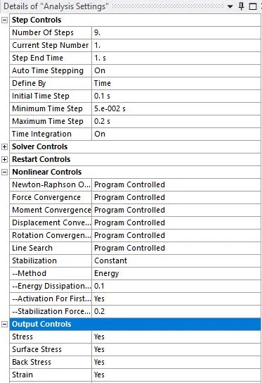
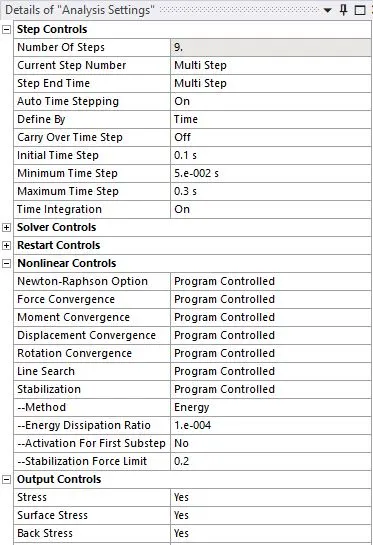
The following changes have been made to save computational time and ease the convergence of the solution.
Auto time stepping is enabled to proceed the solving in small time increment steps.
Weak spring and large deflection options are also enabled to aid in solving.
The stabilization option is switched to constant and 0.1 is provided as an energy dissipation ratio.
First-time step:
Remaining time steps:
Results:
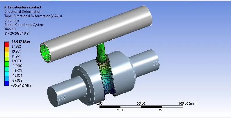
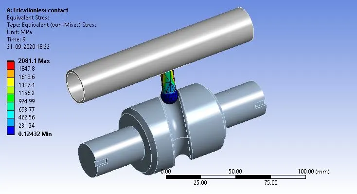
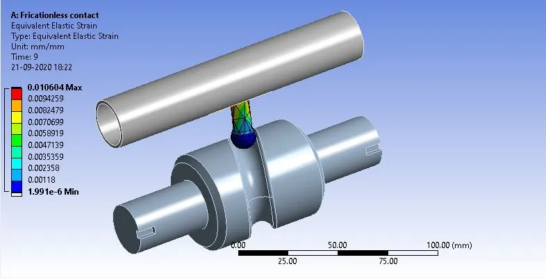
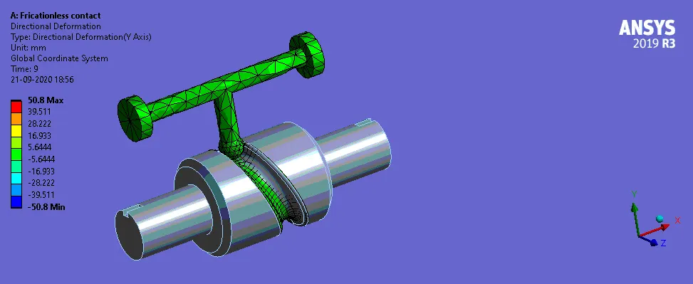
Case:1 Contact between Cam and follower is Frictionless.
Direction deformation:
Equivalent stress:
Equivalent Elastic strain:
Animation for the Direction deformation:
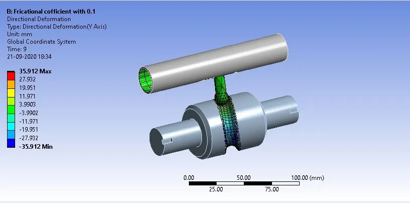
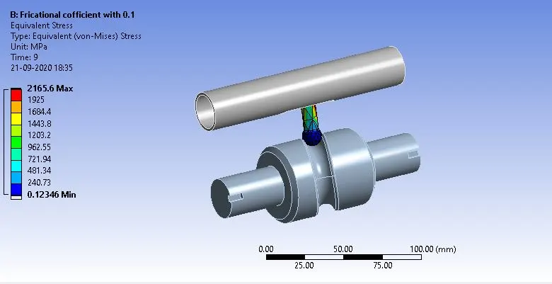
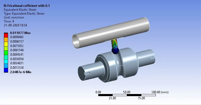
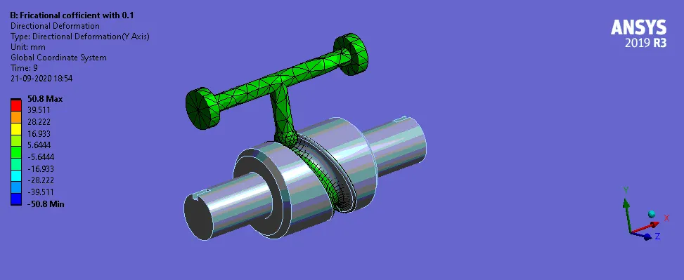
Case:2 Contact between Cam and follower is Frictionl with a coefficient of Friction with 0.1.
Direction deformation:
Equivalent stress:
Equivalent Elastic strain:
Animation for the Direction deformation:
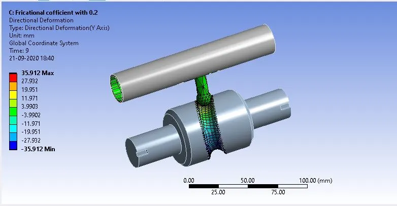
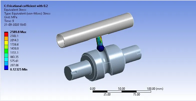
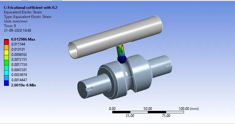
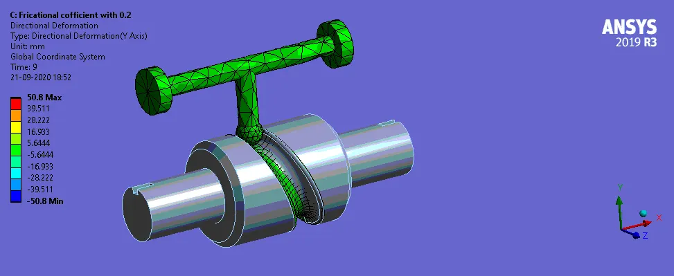
Case:3 Contact between Cam and follower is Frictionl with a coefficient of Friction with 0.2.
Direction deformation:
Equivalent stress:
Equivalent Elastic strain:
Animation for the Direction deformation:
Conclusion:
From the results, we can observe the equivalent stress is varying more or less in a sinusoidal manner regarding the time. This is attributed to the fact that with the rotation of the cylindrical cam the contacting surface between the follower and cylindrical cam changes which change the direction of force reactions during the course. Because of the particular grooved path initially, force reaction acts from the right side on the follower, and with time as the follower moves further this reactive force acts from the left side. Along with force direction, its magnitude is also changing in a similar fashion i.e increasing at the beginning and then decreasing with time. This will become clearer from the force reaction results of the simulation.
| S.No | Case-1 | Case-2 | Case-3 |
| Total deformation | 35.91 | 35.91 | 35.91 |
| Equivalent stress | 2081 | 2165 | 2589 |
| Equivalent Elastic strain | 0.016 | 0.011 | 0.012 |
Now after comparing the three cases we can see that as the frictional coefficient is changed from zero in frictionless contacts to a value of 0.2 in the third case Magnitude of Equivalent stress developed is increasing. This variation is quite expected since with increases in frictional coefficient between surface more resistance is developed during the motion of the follower and hence force is acting on the follower which causes the development of higher stresses.