Simulation of a backward facing step in OpenFOAM
Problem Statement: To simulate backward facing step geometry in openfoam
The given conditions for the problem are that the flow is incompressible, laminar and viscous and transient simulation is to be performed.
Steps Involved:
- Identify the appropriate solver for the given conditions.
- Change the blockMeshDict file as per the dimensions of the given geometry.
- Perform Mesh operation and view in paraview.
- Change the parameters in ControlDict file - provide right value of time step.
- Verify the boundary and initial conditions.
- Solve the problem.
- Post-process the results.
- State conculsions and limitations of the results.
1.Solver identification:
For this problem, icoFoam solver is used. This is because, the flow is considered to be laminar, incompressible and viscous. icoFoam solves incompressible laminar navier-stokes equation using the PISO algorithm and icoFoam code is inherently transient - All these are the characteristics required to solve the current problem. icoFoam solver is within the incompressible folder of tutorials.
Path: $FOAM_TUTORIALS/incompressible/icoFoam
2. Generating blockMeshDict file:
Before generating the blockMeshDict file, geometry dimensions and the number of blocks have to mapped properly.
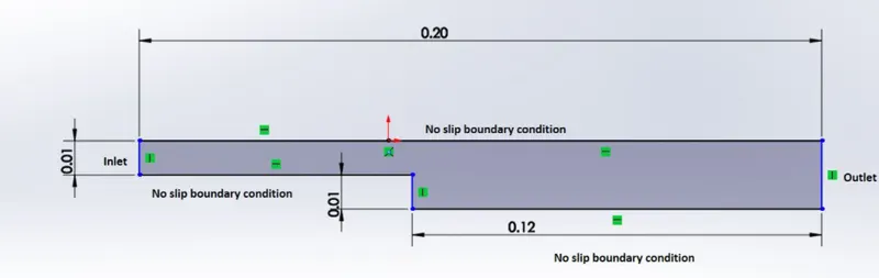
The above image indicates the dimensional details of the geometry considerd for this simulation. Dimensions are in meter. As mentioned in the image, left end indicates the inlet and right end indicates the outlet, for remaining surfaces, no slip boundary condition is applied.
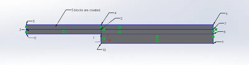
In total 5 blocks are created to facilitate for blockMesh. As this is a 2D simulation, only 1 part is considered in z direction while dividing the domain. The above image indicates the front side and similarly the blocks are named on the rear side.
- The starting point at left bottom is taken as the reference point.
- Block faces are named by observing them from the outside in anticlockwise direction (openfoam nomenclature follows naming from the inside in clockwise direction).
- Through the same nomenclature, blocks are created - by combining both front and back faces with respect to each block.
blockMeshDict file:
/*--------------------------------*- C++ -*----------------------------------*
  =========                 |
  \      /  F ield         | OpenFOAM: The Open Source CFD Toolbox
   \    /   O peration     | Website:  https://openfoam.org
    \  /    A nd           | Version:  8
     \/     M anipulation  |
*---------------------------------------------------------------------------*/
FoamFile
{
    version     2.0;
    format      ascii;
    class       dictionary;
    object      blockMeshDict;
}
// * * * * * * * * * * * * * * * * * * * * * * * * * * * * * * * * * * * * * //


convertToMeters 1;

vertices
(
    (0 0 0)
    (0.08 0 0)
    (0.08 0.005 0)
    (0 0.005 0)
    (0.08 0.01 0)
    (0 0.01 0)
    (0.20 0.01 0)
    (0.20 0.005 0)
    (0.20 0 0)
    (0.20 -0.01 0)
    (0.08 -0.01 0)
    (0 0 0.01)
    (0.08 0 0.01)
    (0.08 0.005 0.01)
    (0 0.005 0.01)
    (0.08 0.01 0.01)
    (0 0.01 0.01)
    (0.20 0.01 0.01)
    (0.20 0.005 0.01)
    (0.20 0 0.01)
    (0.20 -0.01 0.01)
    (0.08 -0.01 0.01)

);

blocks
(
    hex (0 1 2 3 11 12 13 14)
    (200 20 1)
    simpleGrading (1 1 1)

    hex (3 2 4 5 14 13 15 16)
    (200 20 1)
    simpleGrading (1 1 1)

    hex (10 9 8 1 21 20 19 12)
    (200 20 1)
    simpleGrading (1 1 1)

    hex (1 8 7 2 12 19 18 13)
    (200 20 1)
    simpleGrading (1 1 1)

    hex (2 7 6 4 13 18 17 15)
    (200 20 1)
    simpleGrading (1 1 1)


);

edges
(
);

boundary
(
    inlet
    {
        type patch;
        faces
        (
            (0 3 14 11)
            (3 5 16 14)
        );
    }
    outlet
    {
        type patch;
        faces
        (
            (8 9 20 19)
            (7 8 19 18)
            (6 7 18 17)
        );
    }
    upperWall
    {
        type wall;
        faces
        (
            (5 4 15 16)
            (4 6 17 15)

        );
    }
    lowerWall
    {
        type wall;
        faces
        (
            (1 12 21 10)
            (1 0 11 12)
            (9 10 21 20)
        );
    }
    frontAndBack
    {
        type empty;
        faces
        (
            (0 1 2 3)
            (3 2 4 5)
            (10 9 8 1)
            (1 8 7 2)
            (2 7 6 4)
            (12 13 14 11)
            (13 15 16 14)
            (20 19 12 21)
            (19 18 13 12)
            (18 17 15 13)

        );
    }
);
mergePatchPairs
(
);


// ************************************************************************* //
Changes made: This is for case 1 where the grading factor is 1.
- Vertices are altered as per the geometry in consideration.
- Number of divisions in x direction is made 200, y direction - 20 and z direction - 1.
- Remaining inlet, outlet, upperwall, lowerwall and front and back are changed according to the geometry.
path:$FOAM_TUTORIALS/incompressible/icoFoam/cavity/system/blockMeshDict
3.Mesh generation
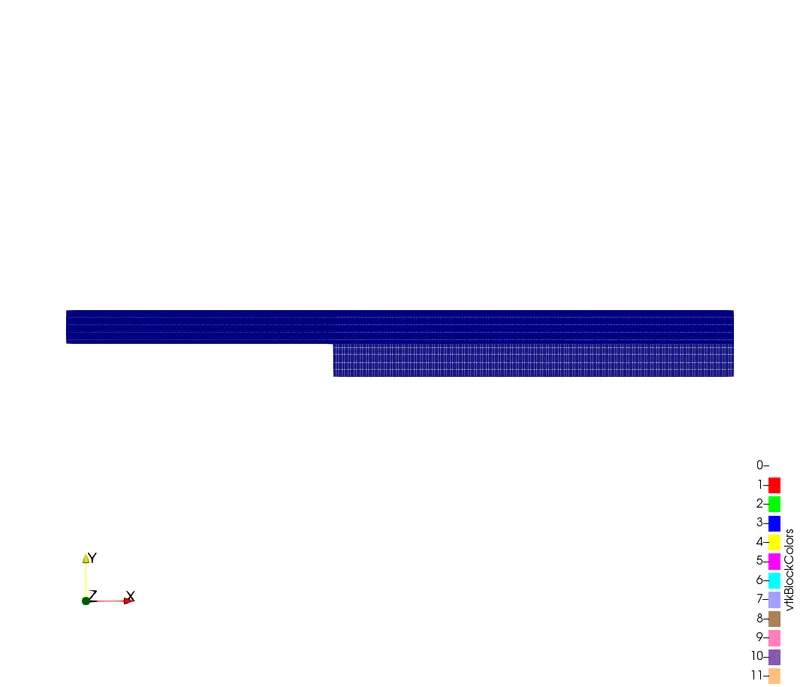
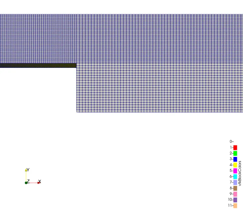
To generate mesh for the above created blockMeshDict file, blockMesh command is typed in the terminal and to check the mesh checkMesh can be used.
The below mesh images are for grading factor 1.
4. ControlDict
This text file contains information related to start time, end time, deltat, format, etc.
/*--------------------------------*- C++ -*----------------------------------*
  =========                 |
  \      /  F ield         | OpenFOAM: The Open Source CFD Toolbox
   \    /   O peration     | Website:  https://openfoam.org
    \  /    A nd           | Version:  8
     \/     M anipulation  |
*---------------------------------------------------------------------------*/
FoamFile
{
    version     2.0;
    format      ascii;
    class       dictionary;
    location    "system";
    object      controlDict;
}
// * * * * * * * * * * * * * * * * * * * * * * * * * * * * * * * * * * * * * //

application     icoFoam;

startFrom       startTime;

startTime       0;

stopAt          endTime;

endTime         0.3;

deltaT          1e-5;

writeControl    timeStep;

writeInterval   50;

purgeWrite      0;

writeFormat     ascii;

writePrecision  6;

writeCompression off;

timeFormat      general;

timePrecision   6;

runTimeModifiable true;


// ************************************************************************* //
In this text file, end time has been set to 0.3 and `deltat`is set to 1e-5. The reason for considering `deltat` to be 1e-5 is to maintain the appropriate Courant number and for this simulation, the maximum courant number observed is 0.2146.
Time step:
To obtain a stable solution, courant number should be calculated correctly and the value should be less than 1 for linear convection problems for the solution to be stable. Courant number is given by : `C = a*(delt)/(delx)`. Here time step is represented by `delt`. For this problem, 1e-5 gives a stable solution.
Path: $FOAM_TUTORIALS/incompressible/icoFoam/cavity/system/controlDict
5. Boundary and initial conditions:
Pressure:
/*--------------------------------*- C++ -*----------------------------------*
  =========                 |
  \      /  F ield         | OpenFOAM: The Open Source CFD Toolbox
   \    /   O peration     | Website:  https://openfoam.org
    \  /    A nd           | Version:  8
     \/     M anipulation  |
*---------------------------------------------------------------------------*/
FoamFile
{
    version     2.0;
    format      ascii;
    class       volScalarField;
    object      p;
}
// * * * * * * * * * * * * * * * * * * * * * * * * * * * * * * * * * * * * * //

dimensions      [0 2 -2 0 0 0 0];

internalField   uniform 0;

boundaryField
{
    inlet
    {
        type            zeroGradient;
    }

    outlet
    {
        type            fixedValue;
        value           uniform 0;
    }

    upperWall
    {
        type            zeroGradient;
    }

    lowerWall
    {
        type            zeroGradient;
    }

    frontAndBack
    {
        type            empty;
    }
}
path: $FOAM_TUTORIALS/incompressible/icoFoam/cavity/0/p
Velocity:
/*--------------------------------*- C++ -*----------------------------------*
  =========                 |
  \      /  F ield         | OpenFOAM: The Open Source CFD Toolbox
   \    /   O peration     | Website:  https://openfoam.org
    \  /    A nd           | Version:  8
     \/     M anipulation  |
*---------------------------------------------------------------------------*/
FoamFile
{
    version     2.0;
    format      ascii;
    class       volVectorField;
    object      U;
}
// * * * * * * * * * * * * * * * * * * * * * * * * * * * * * * * * * * * * * //

dimensions      [0 1 -1 0 0 0 0];

internalField   uniform (0 0 0);

boundaryField
{
    inlet
    {
        type            fixedValue;
        value           uniform (5 0 0);
    }

    outlet
    {
        type            zeroGradient;
    }

    upperWall
    {
        type            noSlip;
    }

    lowerWall
    {
        type            noSlip;
    }

    frontAndBack
    {
        type            empty;
    }
}
The only change made wrt boundary conditions is in the velocity text file. In boundary field, the inlet velocity is set to 5m/s.
path: $FOAM_TUTORIALS/incompressible/icoFoam/cavity/0/U
6. Solution details:
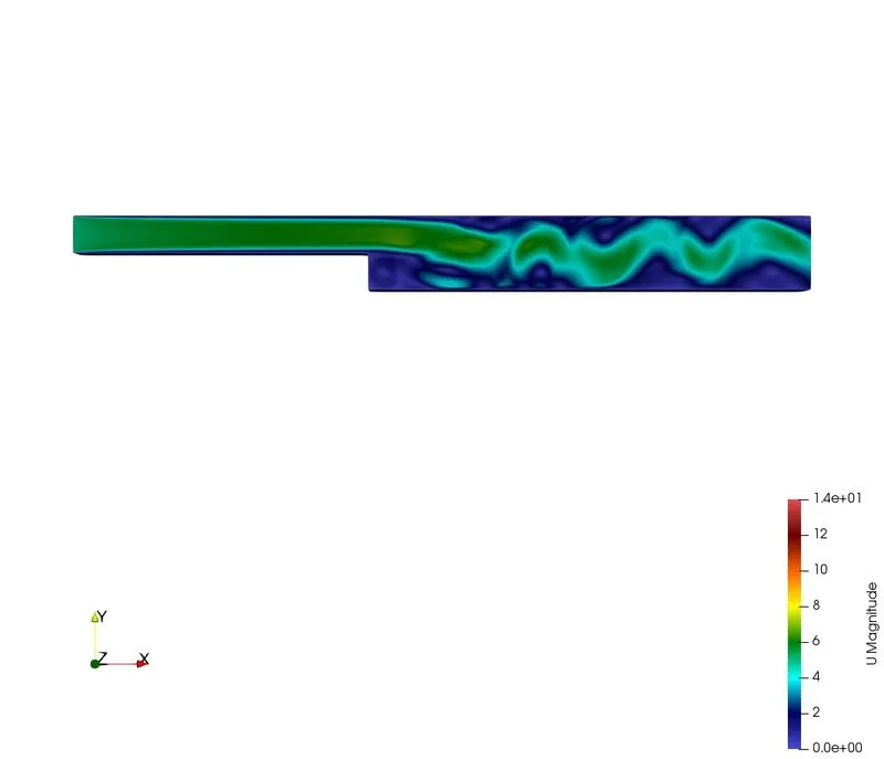
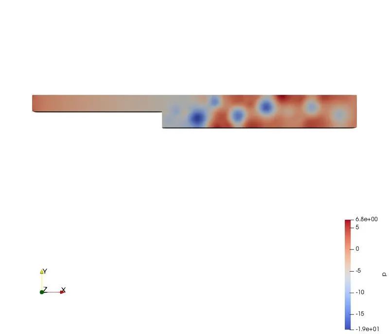
For grading factor 1
Velocity variation
Pressure variation
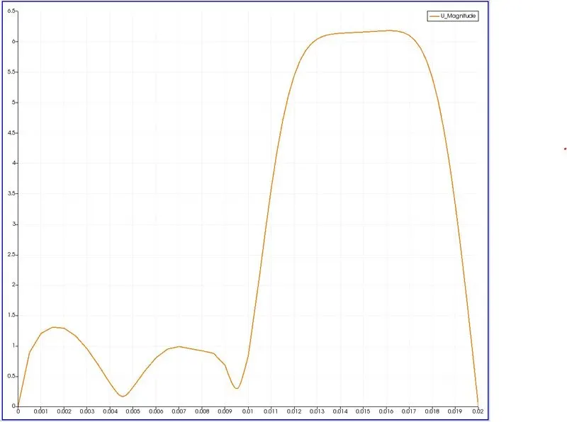
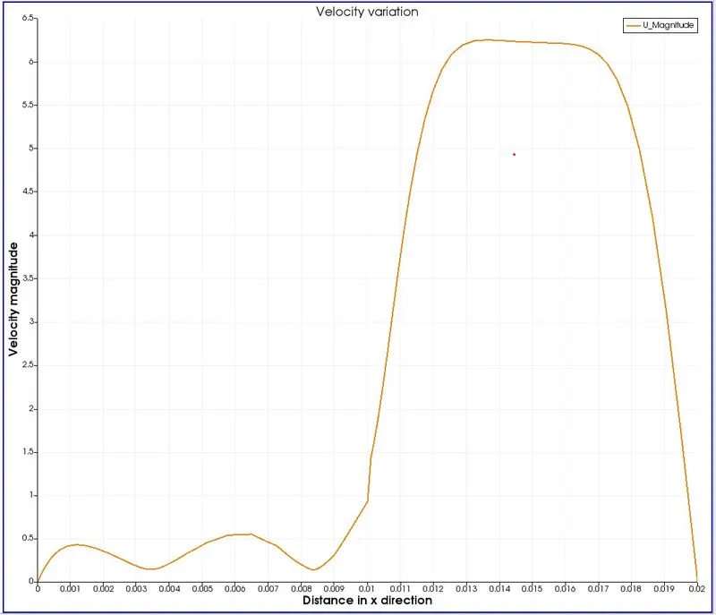
Velocity variation at 85mm from the inlet:
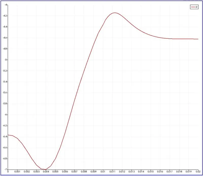
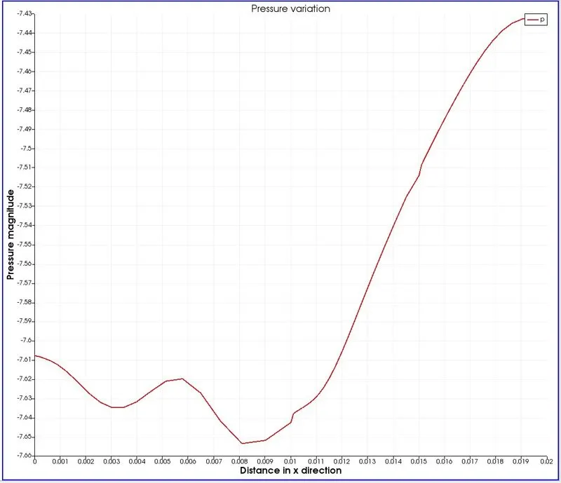
Pressure variation at 85mm from the inlet:
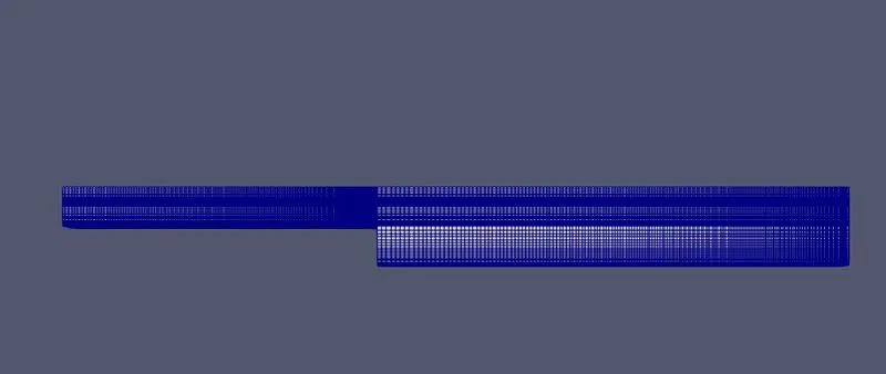
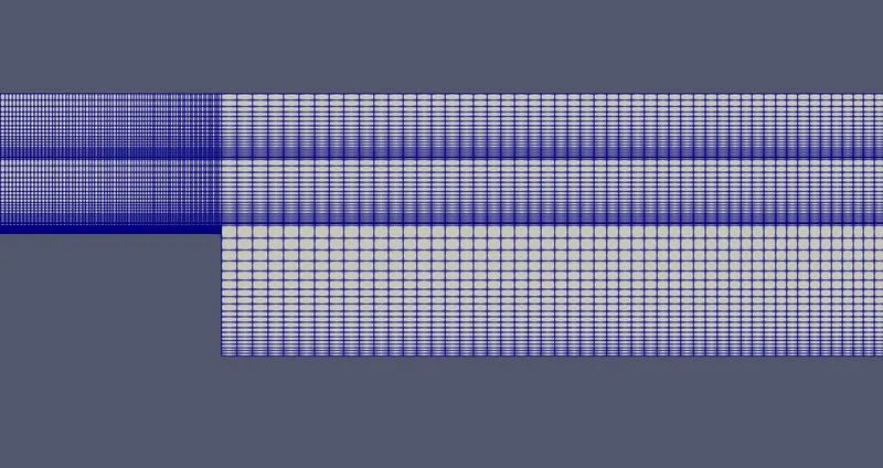
Case 2: Grading factor - 0.2
In this case, mesh near the walls of each block is refined by giving a grading factor of 0.2.
The mesh and results associated with this case are mentioned below:
Mesh:
Velocity variation:
Pressure variation:
Velocity variation at a distance of 0.085m from the inlet:
Pressure variation:
Conclusions:
Need for grading factor in meshing:
While normal grading factor (1) in each direction provide satisfactory results, to get accurate results, one can refine the areas of focus. This also helps with computational efficiency. In this problem, flow near the walls is observed to be important and hence the near wall areas are refined by a factor of 0.2. The grading factor is also called cell expansion ratio. The factor of 0.2 indicates that cells at the end of the block are smaller than those at the start. To define correctly, the reference axis considered is also important.
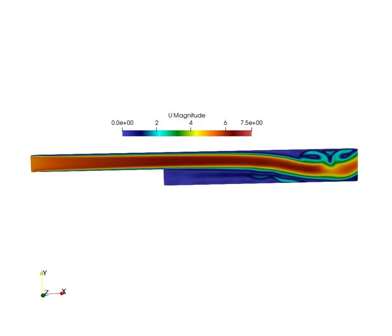
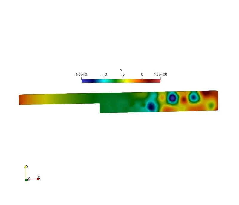
When results of velocity variations in grading factors 1 and 0.2 are compared, it can be inferred that velocity fluctuates more in the first case in initial stages of simulation.
Backward step simulation is important, because it is used to study the reattachment of fluid molecules in the flow region. Flow separation is often characterized by increased drag and reduced overall efficiency and many more problems. By studying the basic variables resposible for flow separation in simple processes such as this, critical properties can be identified and methods can be determined to reduce their effects.
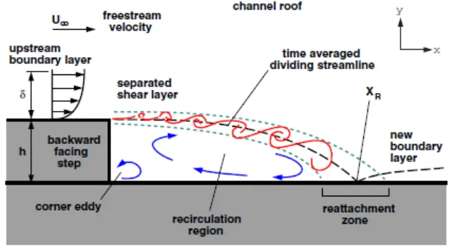
The characteristics of flow mentioned in the above image, can be observed in results - in both the cases.