External flow simulation over an Ahmed body.
Aim: To simulate external flow over Ahmed body and evaluate drag and lift co-efficients along with velocity and pressure contours.
Theory:
One of the major concerns in automobile industry is the pollution caused. This can be material wastage, emissions, etc. Collectively, all different kinds of pollutions from automobiles contribute towards global warming and many other ill effects. To counter this, it is necessary to arrive at an optimal design for the automobile. In this study car geometry has been given the focus.
Factors such drag, lift, wake, etc. are important when aerodynamic efficiency and fuel consumption are considered for any car design. Ahmed body was first proposed by Ahmed and his team in 1984. Studying this body provides us with values such as drag and lift, which can be compared with the real-world experiments and can be used to arrive at an optimal design. Although Ahmed body is a simple bluff body, it does include some features relevant to normal automobiles. For eg: the slant at the rear section of the body helps to visualize how wake varies and this can be altered by changing slant angles.
When all these factors are considered, it becomes important to study and validate the results obtained from Ahmed body.
Design details are displayed below:
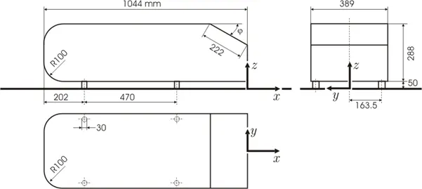
As the geometry in consideration is symmetric wrt Y-axis, the model is cut in half and the results are obtained for the cut model. The same procedure is carried out for all the other cases as well.
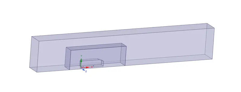
Ahmed body is considered as a reference body to study aerodynamic parameters such as drag, lift and wake. When the resultant forces of a body are considered based on pressure, the body is termed as bluff body. For such bodies drag, lift and wake are a by product of pressure differences. In case of Ahmed body, due to pressure difference at the front and rear section, a negative pressure is created and this increases the drag. As the body is simple in its construction and the results can be accurately matched with similar automobile bodies, this is given importance in the domain external simulation over an automobile. Not only just drag forces, the wake created due to the separation of fluid particles from the boundary layer can also be effectively visualized.

Governing equations:
For this problem, K-epsilon turbulence model is considered. And it is a two equation model wherein the first equation is used to determine turbulent kinetic energy (K) and the second equation is used to determine turbulent dissipation rate (epsilon). The equations are mentioned below:
`(del(rho*k))/(delt) + (del(rho*epsilon*k))/(delx_i) = del/(delx_j)(mu_t/sigma_k*(delk)/(delx_j))+ 2*mu_t*E_(ij)^2-rho*epsilon`
`(del(rho*epsilon))/(delt) + (del(rho*epsilon*u_i))/(delx_i) = del/(delx_i)*(mu_t/sigma_epsilon*(delepsilon)/(delx_j))+C_(1epsilon)*epsilon/k*2mu_t*E_(ij)^2-C_(2epsilon)*rho*(epsilon^2)/k`
Case 1: Ahmed body element size - 8mm
For the first case, simulation is performed by considering the highest number of elements (as per student license). Value for first layer thickness is calculated as shown below:
`Y^+ = (rho * U_tau * Y)/mu ; U_tau = sqrt(tau_w/rho) ; C_f = 0.0032584 * Re^-0.2; Re = (rho* V* L)/mu`
where Y is the first layer thickness, `tau_w` is the wall shear stress, `C_f`is the skin friction co-efficient
The reference values considered for calculation are:
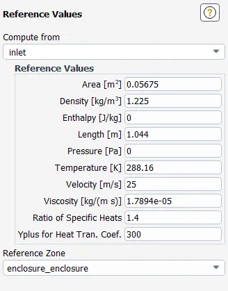
- Reynolds number obtained by considering the above reference values – 1,786,776
- Y+ value is considered to be 30, since the K-epsilon model is used.
- By solving all the above equations, the value of Y is calculated to be 0.4289mm.
There are many parameters that can be varied for eg: element size of second enclosure, number of inflation layers, value of first layer thickness, velocity, etc. But in this study, only size of Ahmed body is varied for grid dependency test and all the other parameters are kept constant.
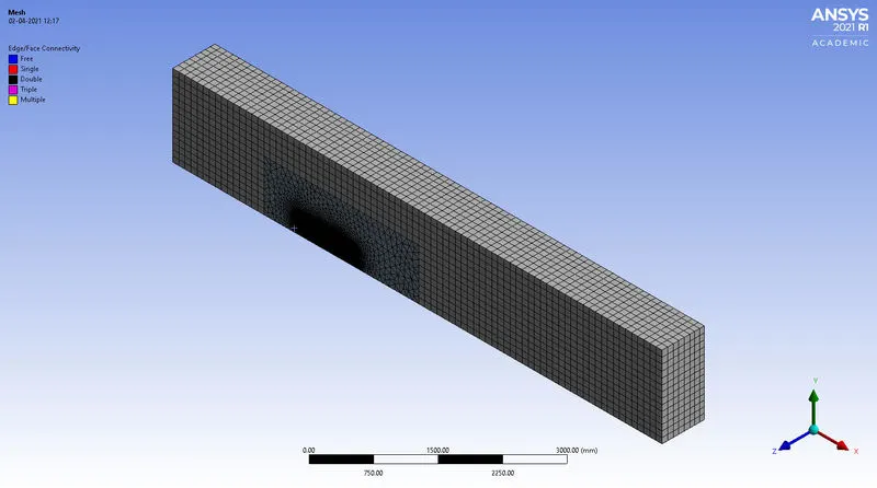
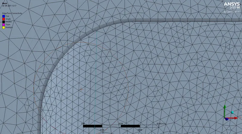
The above image indicates inflation layer and for this study 5 layers are used.
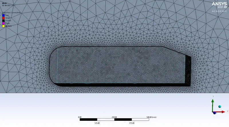
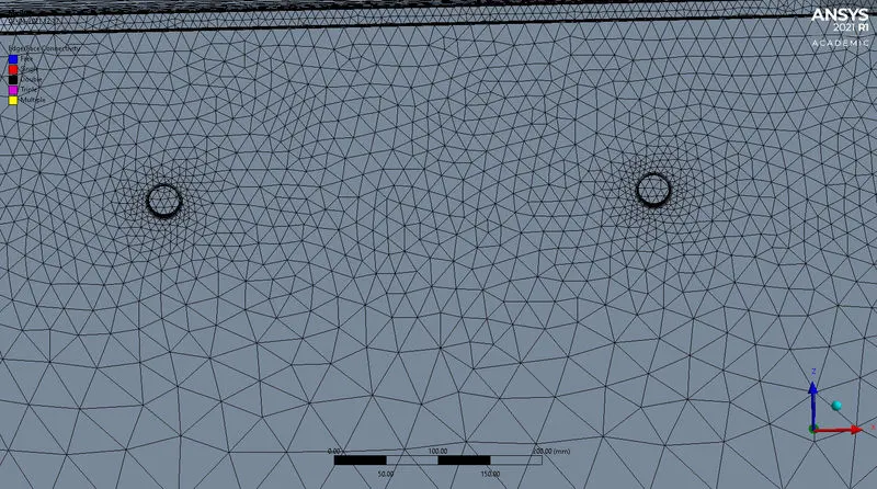
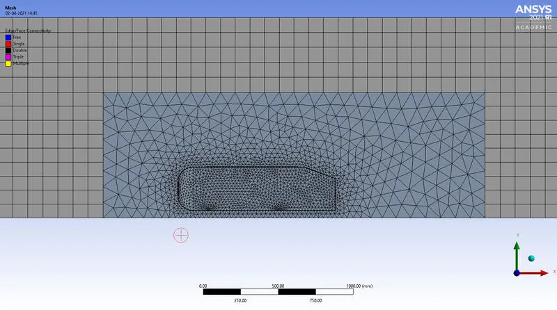
- Above images indicate mesh details of the Ahmed body – It includes mesh quality of enclosures (top image), mesh of Ahmed body (2nd image), mesh depicting inflation layer (3rd image), edge sizing in the bottom image.
Results:
- Next few images indicate the details of results in terms of velocity contour, pressure contour, drag co-efficient and lift co-efficient.
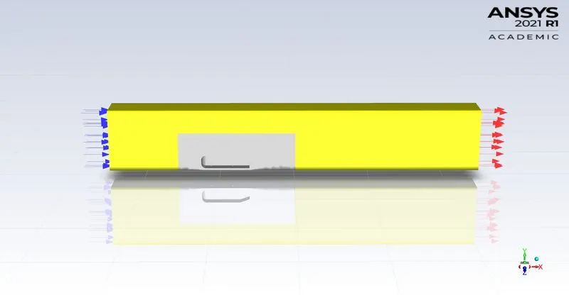
- Represention of Ahmed body with inlet and outlet in Fluent.
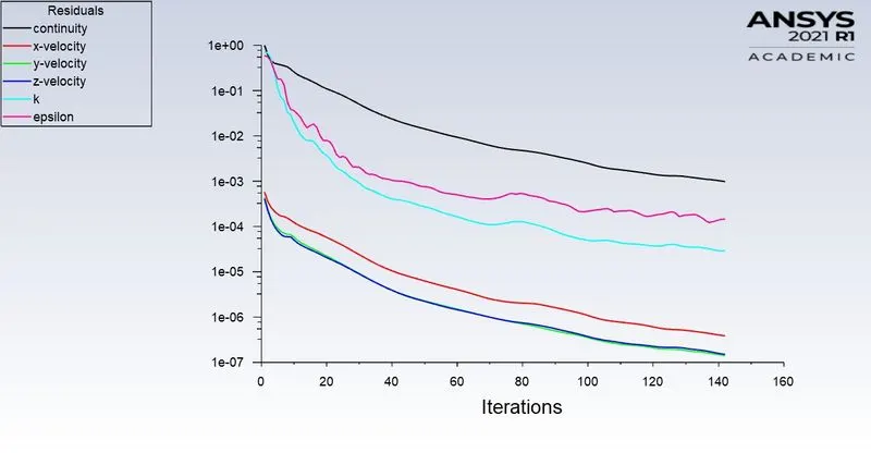
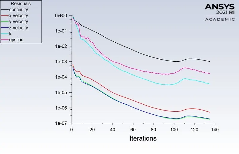
- From the image, it can be inferred that the solution reaches convergence at 142nd iteration.
Velocity contour :
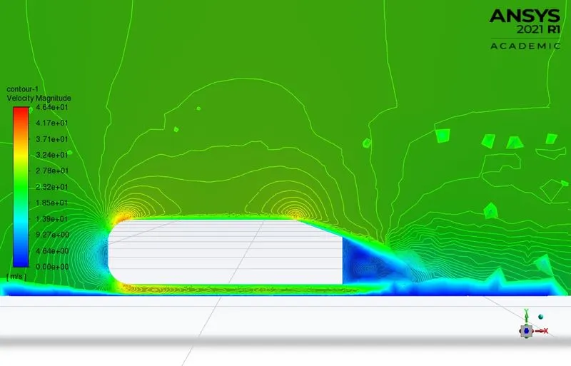
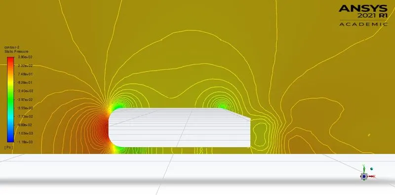
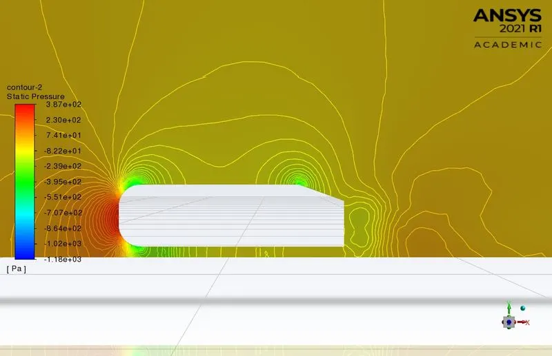
Reason for negative pressure at the rear section
Ahmed body is termed as a bluff body because the aerodynamic forces are considered in terms of fluid pressure variations. So, when fluid flow is considered over the body it follows the geometry until it reaches the rear end of the body. Here, due to the slant angle, fluid separation occurs and also the fluid has particular velocity – in this case 25m/sec. Due to separation, the fluid velocity at the rear end of the geometry will be near to the free stream velocity, which will be high.
According to Bernoulli’s theorem, high velocity induces low pressure and vice-versa. Hence, due to flow separation, recompression of the fluid at the rear end is avoided. Because of this, low pressure is maintained at the rear end and a wake is generated which moves from high pressure region to low pressure region.
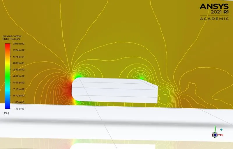
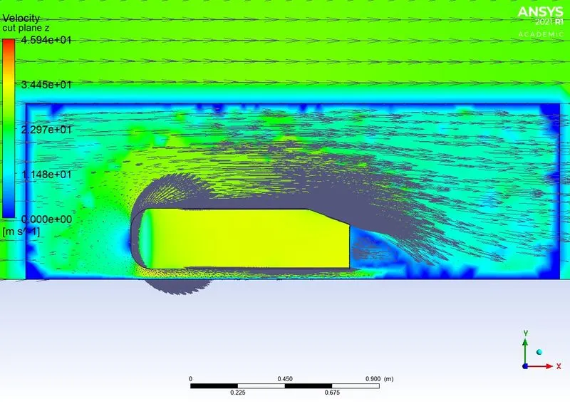
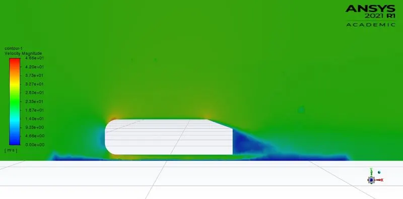
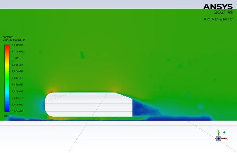
- The wake formed due to the separation of fluid from the boundary layer can be clearly seen in the above image.
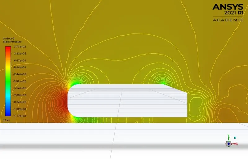
- This is particularly due to the pressure difference. Fluid flows from high pressure(top) region to low pressure region(rear), which creates a small eddy like shape and this eddy is responsible for increasing the vehicle drag.
Drag co-efficient:
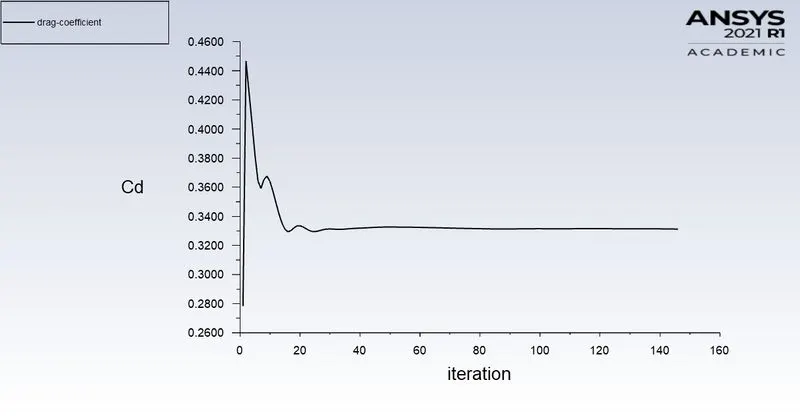
- The above plot indicates the value of drag co-efficient for this refined case to be 0.33.
Lift co-efficient:
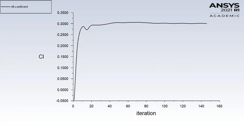
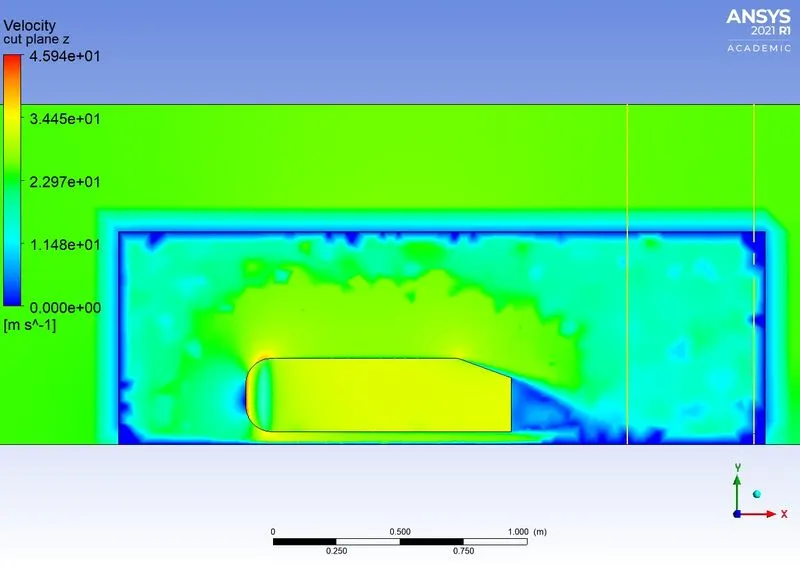
- The above image indicates lines created at different positions to measure velocity and pressure. First line is named line1 and second line is line2.
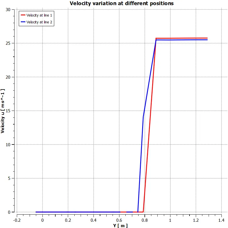
- Above variation depicts that the velocity doesn't differ much once it separates from the boundary layer.
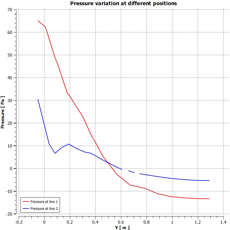
- This indicates that the pressure reaches a negative point after separating from the boundary layer and the reason for the same has been explained before the image of pressure contour.
case 2 : Ahmed body element size 10mm
In this case the every other parameter is kept constant with variation seen only in the element size of Ahmed body.
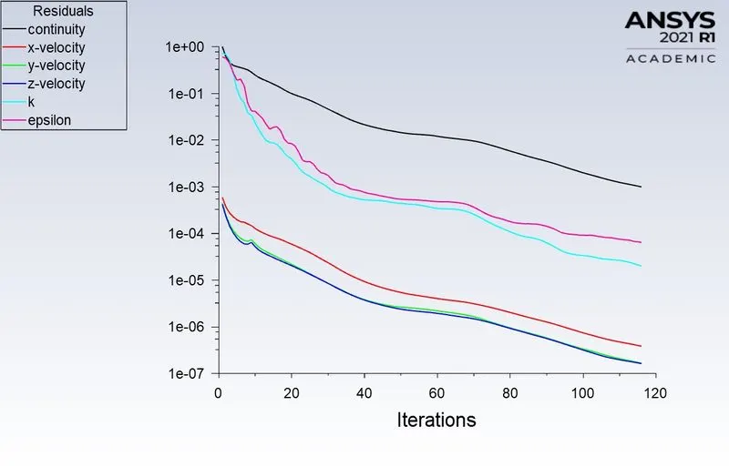
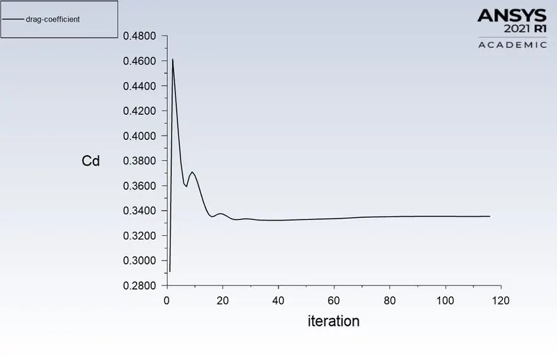
Residuals:
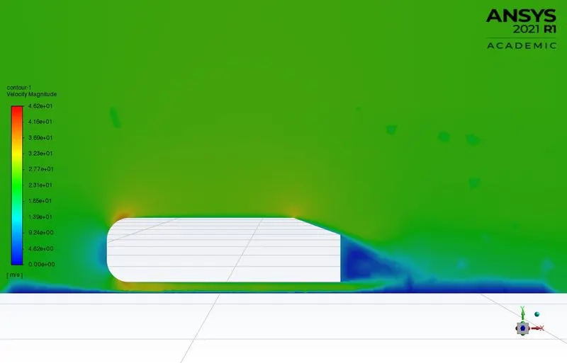
Velocity contour:
Pressure contour:
Case 3: Ahmed body element size - 15mm
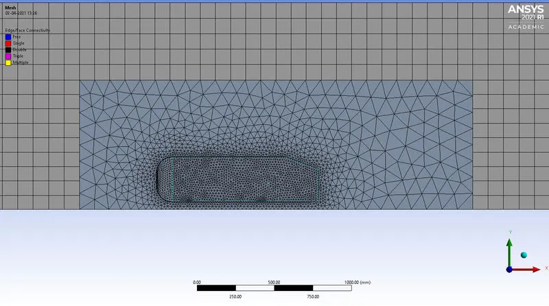
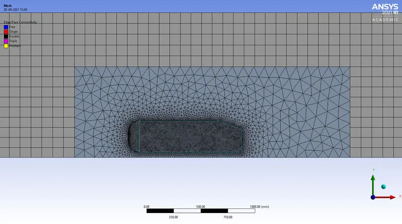
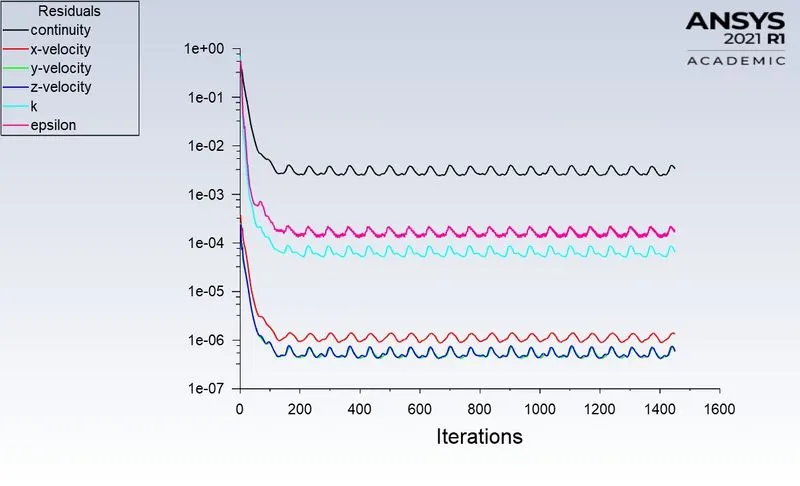
- Above image indicates the mesh quality for element size of 15 mm.
Velocity contour:
Pressure contour:
Case 4: Ahmed body element size 20mm
Pressue contour:
Velocity contour:
Grid Independency test:
when a design is considered flow flow simulation, it is important to fix a particular element size which can provide optimal or accurate results. This element value can be arrived at by various procedures. One such procedure is by grid independency/dependency test. This test also helps to standardize number of elements for a given design. In this study 4 cases are considered by varying size of Ahmed body elements from 8mm to 20mm.
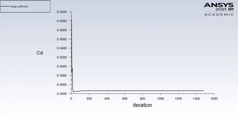
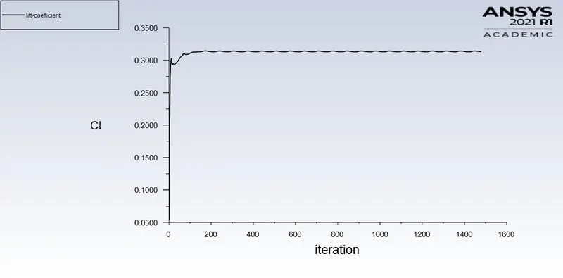
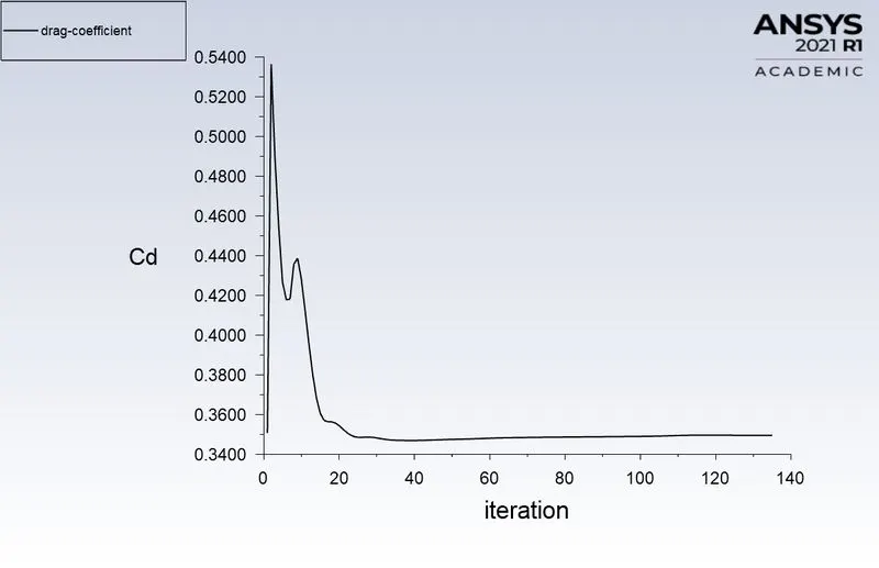
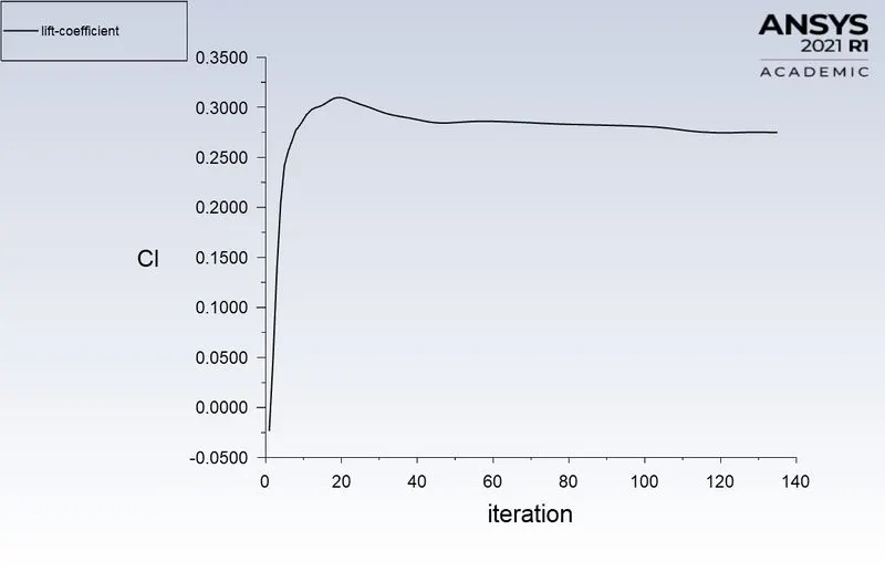
The parameters observed for variations are drag and lift co-efficients. In this view, it can be inferred from the table below, that the variation of drag co-efficient is not much significant for all the cases, but lift co-efficient varies a little. Again the difference in values are very less. As this simulation has been performed on Ansys student version, 0.5 milllion elements were the limit. Hence, the least element size considerable is 8mm.
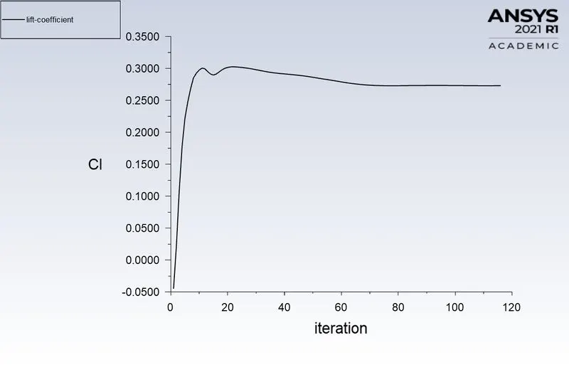
For 10mm element size, the drag co-efficient is observed to be 0.33 which is the actual value for the Ahmed body for a velocity of 25 m/sec. The variation in this value is very less 0.004, even after decreasing the element size to 8mm. Only a little variation is observed in lift co-efficient. So, it can be concluded that at the element size of 10mm, grid independency is achieved. Decreasing element size beyong this value has not much effect on the solution.
|
Case number |
Element size (Ahmed body) mm |
Number of nodes |
Number of elements |
Drag co-efficient |
Lift co-efficient |
Iterations to converge |
|
1 |
8 |
140613 |
472554 |
0.3313 |
0.3010 |
142 |
|
2 |
10 |
96726 |
314728 |
0.3353 |
0.2729 |
118 |
|
3 |
15 |
53795 |
166584 |
0.3463 |
0.3131 |
More than 1400 |
|
4 |
20 |
38706 |
110122 |
0.3495 |
0.2747 |
135 |
Significance of separation point
In a fluid flow, pressure increases as the flow moves ahead. This means that the flow needs more momentum to break this pressure and keep moving. At some point the momentum of the flow is overcome by the pressure acting and this is called Adverse pressure gradient. At this point flow separates from the boundary layer. This point is important because, in case of Ahmed body, the flow detachment happens somewhere near the top of slant angle and by varying slant angle it is possible to vary the separation point and get decreased aerodynamic drag values.
Conclusions:
- For the given velocity of 25m/sec, the drag co-efficient of 0.33 has been obtained.
- Grid independency is achieved at an element size of 10mm.
- Wake formation due to pressure differences is clearly observed in the velocity contour.
- Increase in drag co-efficient can be attributed to negative pressure at the rear end of the body.
- Different parameters such as Y+, velocity, mesh quality, inflation layer matter for resultant aerodynamic values.
References:
1. http://ijaret.com/wp-content/themes/felicity/issues/vol3issue1/datta.pdf
2. https://www.mech.kth.se/courses/5C1211/BluffBodies.pdf
3. http://www.iosrjournals.org/iosr-jmce/papers/vol12-issue4/Version-3/M012438794.pdf