Simulating Cyclone separator with Discrete Phase Modelling
Objective: To simulate and understand the necessary requirements to arrive at an optimal separator efficiency by considering different flow/particle velocities and different particle diameters.
1. Introduction:
Cyclone separators are used to get rid of bigger particles in flue gases. These are used to remove particles above size 10e-6m, but some of the separators are used to remove particles of size 2e-6m. There are different types of cyclones depending on the way flue gases enter the separator inlet, but the working principle is same for all types. In this study reverse flow separator with a tangential rectangular inlet is considered.
Principle of operation - When flue gas with particulate matter enter through the inlet, there will be a pressure drop due to the tornedo created inside the cyclone. This tornedo results in centrifugal force which further acts on the dense and bigger particles. Due to this force, the bigger particles hit the wall and reach the bottom of the cyclone - from where they will be removed. The clear gas and lower density smaller particulate matter reach the top of the cyclone due to their lower inertia. From here, the clear gas will be sent to further processing where minute particulate matter will be removed.
Cyclones can remove particles from 50% to 99%, depending on the separation efficiency. This efficiency depends on the particle diameter, cyclone diameter, cyclone length, pressure drop, etc. The efficiency is observed to be high when the flue gas contains large number of bigger particulate matter.
Cyclone separator can be used in various applications where high pressure and temperatures are involved like, gas cleaning process, pollution control, coal dust removal process, etc.
1.1 Empirical models:
There are 4 different empirical models to calculate cyclone separator efficiency.
1.11 Lozia and Leith model
This model is based on force balance and according to this model, the particle is influenced by two forces - centrifugal and flow resistance when it is in a vortex flow.
1.12 Lie and Wang model
According to this model, particles that are not collected at the bottom of the cyclone separator, do not have constant radial velocity and radial concentration profile. This means that, due to variable radial velocity, the particles get re-entrained inside the separator. This model also relates the tangential velocity of the particle with its radial velocity.
1.13 Koch and Licht model
This model mainly describes the particle behaviour at the entry and at the collection points. This model assumes that a particle's tangential velocity is the same as that of the flow tangential velocity - meaning that there is no resistance or slip between individual particles and the flow. With these assumptions, this model can be used to predict turbulent nature of cyclone separators and the time flow particles remain within the separator (gas residence time).
1.14 Lapple model
This model is also based on force balance like 1.11, but without considering force balance. According to this model, particles covering half of the inlet diameter/width will be collected at 50% efficiency and for this the model assumes that the particles are evenly distributed at the inlet.
1.2 Cyclone separator efficiency:
This is the ratio of particles collected at the bottom of the separator to the total number of particles that entered the separator.
`eta_c`= Particles at the outlet/Particles at the inlet.
2. Approach:
This study is sub-divided into 2 groups, wherein the first one focuses on varying particle diameter with constant velocity and 2 one focuses on varying velocity with constant particle diameter. For both the approach remains same, the changes made are - while defining DPM sources diameter is changed for the 1st group and inlet velocity is changed for the 2nd group.
- The cyclone separator model is imported to spaceclaim and the fluid volume is extracted - other than fluid volume, all other parts are supressed for physics.
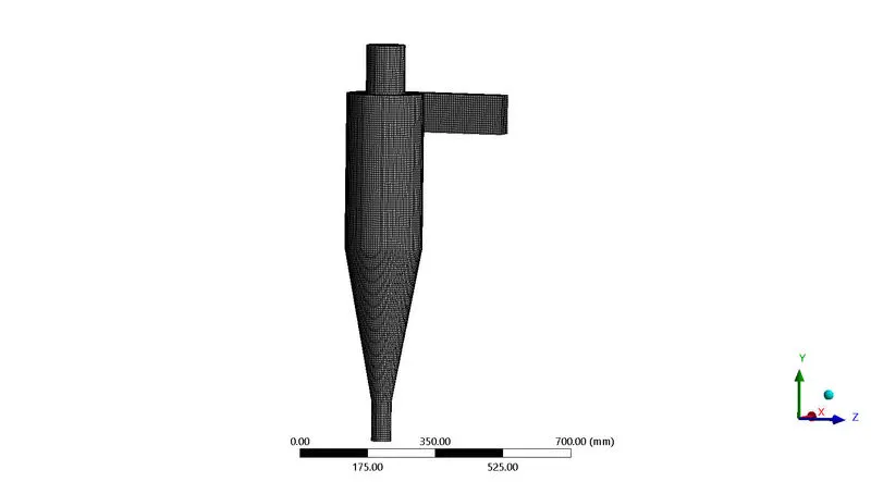
- Mesh of size 6mm is created with capture curvature enabled.
- 1 inlet and 2 outlets are created with named selections.
- Standarad K-epsilon is enabled.
- Discrete phase is defined - interaction with continuous phase is enbled.
- Updating DPM sources is set for every 10 iterations.
- Injection properties are defined.
- Inlet velocity is entered in boundary conditions - DPM state is changed to reflect.
- DPM status at the outlets is kept as escape.
- Standard initialization is done.
- Calculation is carried out for 600 iterations.
- Animation is created in CFD-Post.
- Separation efficiency and pressure drop are calculated for the observed values.
3. Pre-processing:
3.1 Geometry:
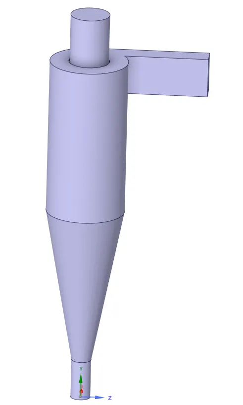
Geometry is imported to spaceclaim and using volume extract option, the fluid volume is extracted and except fluid volume, all the other parts are suppressed for physics.
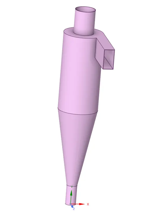
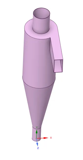
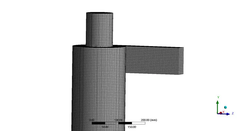
The below image indicates the fluid volume.
3.2 Mesh:
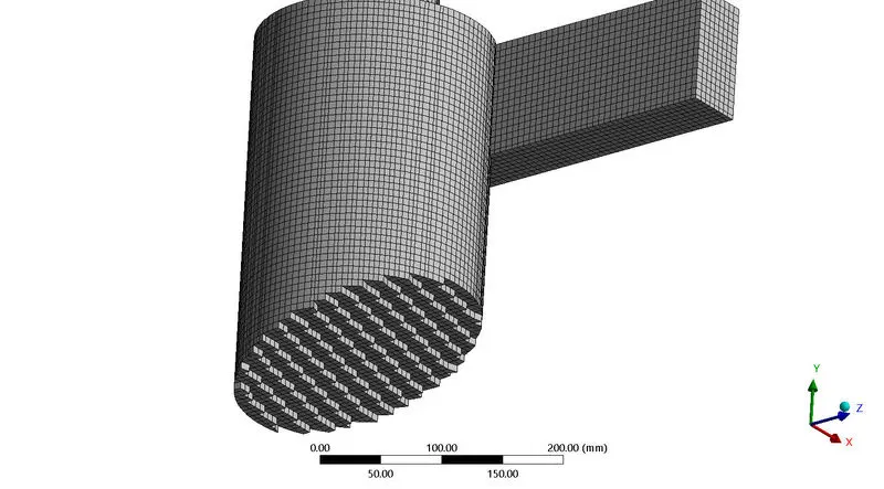
For this study, cartesian meshing approach is used. This allows to create hex mesh which provides better convergence rate and accuracy compared to other types of mesh. Below table indicates the mesh details.
|
Mesh Parameters |
Value |
|
Mesh size |
6mm |
|
Curvature min size |
6e-002mm |
|
Curvature Normal angle |
120 |
|
Number of nodes |
104258 |
|
Number of elements |
93879 |
|
Element order |
Linear |
3.3 Solver:
- For this study, standard k-epsilon model with swirl dominated flow enabled.
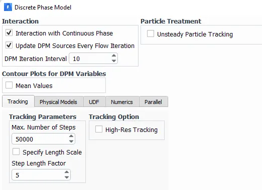
- In discrete phase model, interaction with continuous phase is enabled. Here, the continuous phase could be the liquid carrying these particles and the interaction with continuous phase allows to estimate realistic values of pressure change.
- Bigger particles could interact with the smaller ones in the continuous phase and this could change the course of travel inside the separator. For eg - Due to collision, some of the particles could remain stuck inside the separator. To get a good idea of such cases, interaction with continuous phase is enabled.
- Also, at the bottom of the below image, number of steps and step length factor defines the time step.
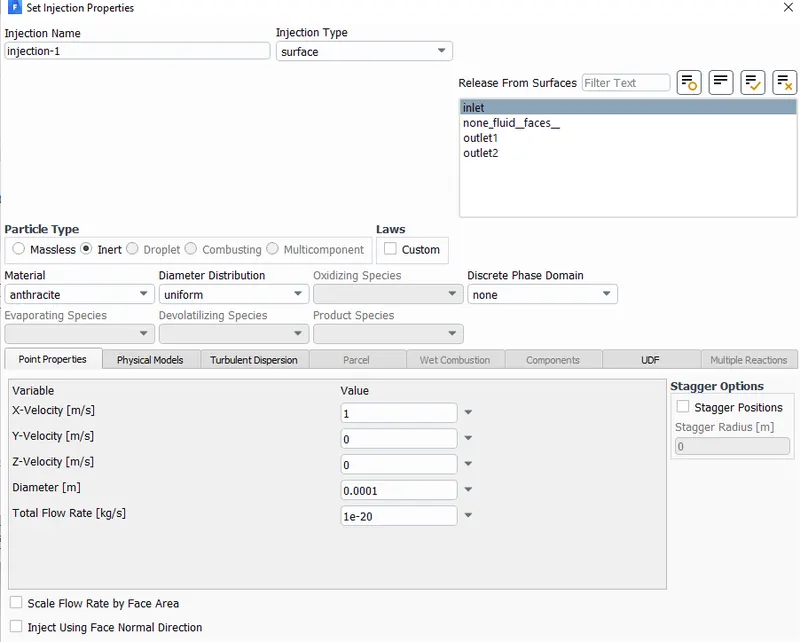
- For particle, anthracite is selected and injection is through the inlet surface, so the mesh decides the number of particles going in. Velolcity is defined as 1m/s and it can be changed according to the requirement.
- The below image indicates what features are used and the values change as per the results required.
4. Results:
This section is divided into 2 sub sections.
- Number of iterations is 600 for all cases. Standard initilization is done.
4.1 Results for varying particle diameter with constant velocity(3m/s):
4.1.1 Diameter - 1`mum`
Residuals:
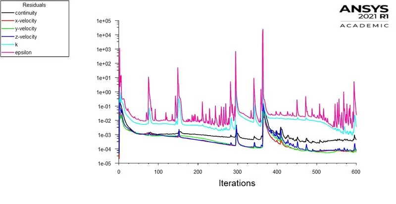

- Separation efficiency is the ratiio of number of particles trapped to the total number of particles tracked. For this it is SE = `74/136*100=55.88%`.
- Similar to the above calculated value, the separator efficiencies are calculated for all the cases and tabulated in a single table in conclusions section along with pressure drop values.
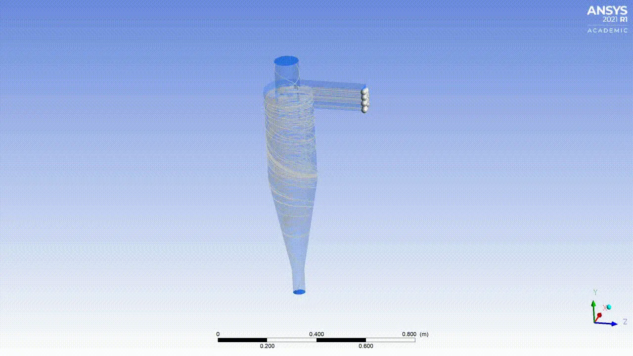
- The above animation is of the particle tracking. It can be seen that some of particles are struck or trapped inside the separator.
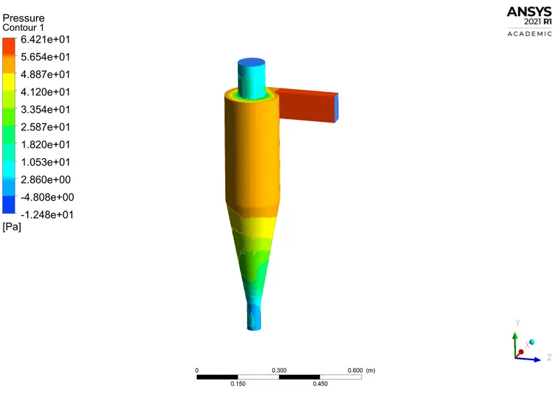
Pressure drop:
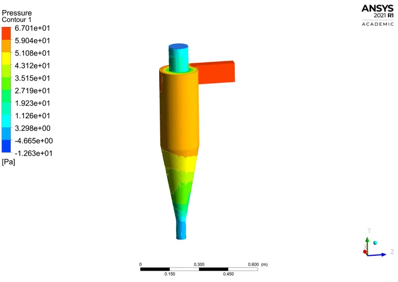
4.1.2 Diameter - 3`mum`
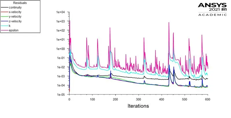
Residuals:

Pressure drop:
4.1.3 Diameter - 5`mum`
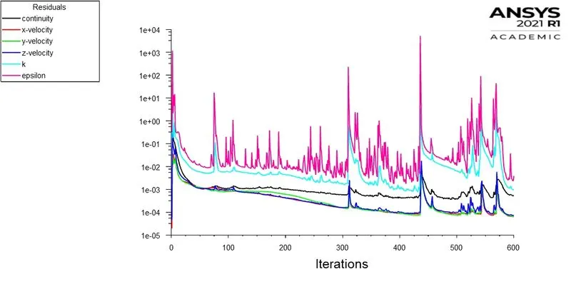
Residuals:

Pressure drop:

4.2 Results for varying velocity with constant particle diamter(5e-6m):
4.2.1 Velocity - 1m/s
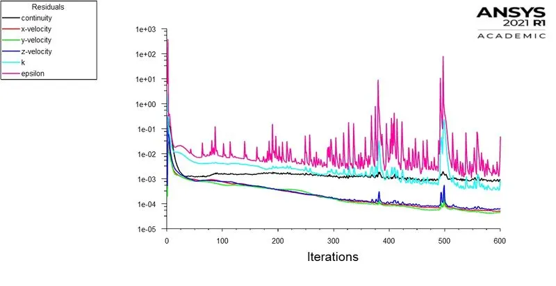
Residuals:

4.2.2 Velocity - 3m/s
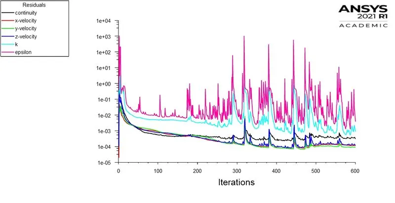
Residuals:

Pressure drop:
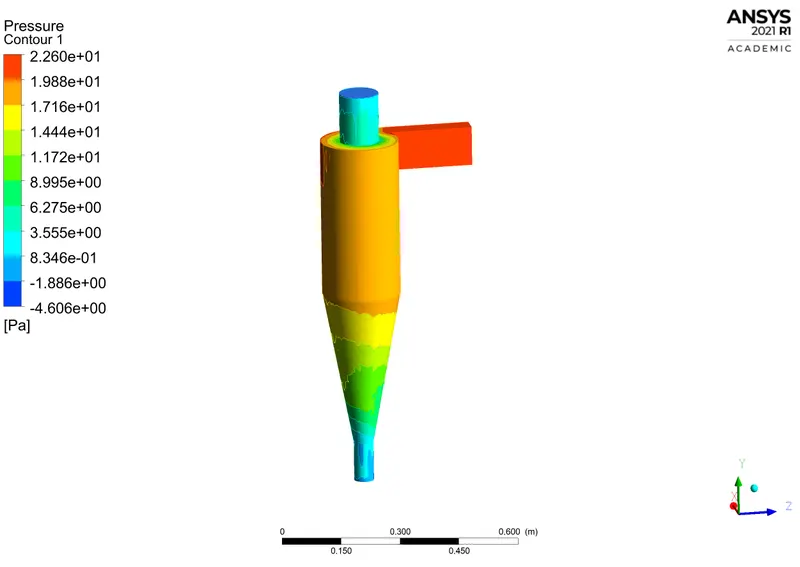
4.2.2 Velocity - 5m/s
Residuals:
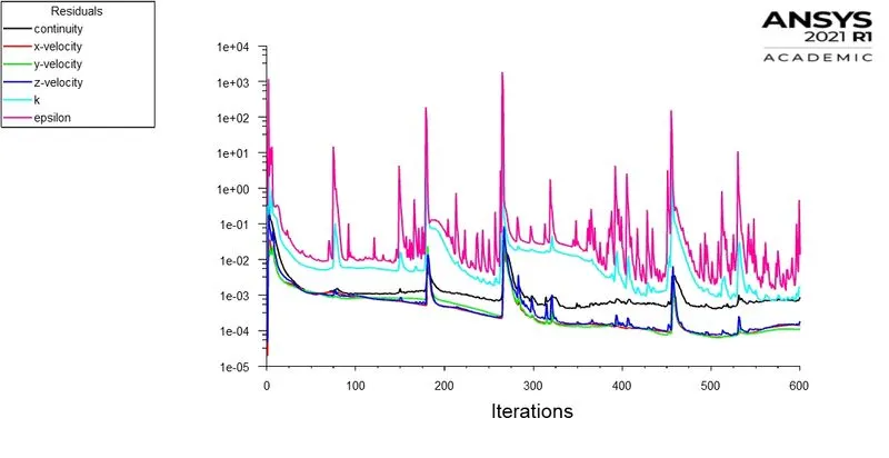

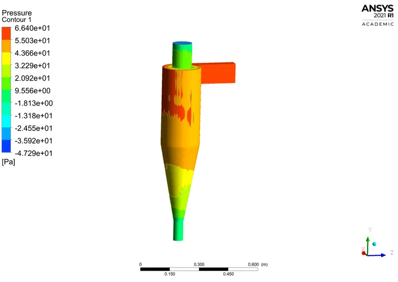
Pressure drop:
5. Conclusion:
| Parameters | Diameter constant with varying velocity (5e-6m dia) | Velocity constant with varying Diameter(3m/s) | ||||
| Cases | 1. 1m/s | 2. 3m/s | 3. 5m/s | 4. 1e-6m | 5. 3e-6m | 6. 5e-6m |
| Separator efficiency in % | 5.14 | 77.2 | 89.7 | 55.88 | 21.32 | 26.47 |
| Pressure drop in Pa | 1.6051 | 17.9905 | 19.11 | 51.7434 | 54.3257 | 52.405 |
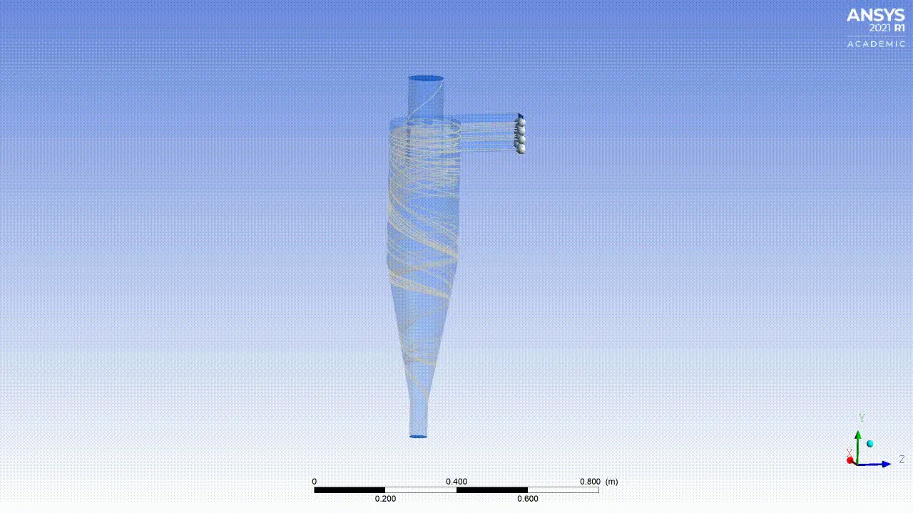
- There are 3 important parameters in particles tracking and they are - escaped, trapped and incomplete. Escaped means that the particles are out of the set boundary. Trapped means that the particles are terminated from their path once they reach the bottom of the separator and incomplete means that the particles are still inside the separator simply swirling around.
- In almost every case exept 6th, there are incomplete particles. This could be due the flow/particle velocity and the energy dissipation of these particles.
- When particles collide with each other due to swirling motion and turbulence, they transfer momentum which cause loss in energy as well as pressure.
- Incomplete particles can be avoided by ensuring proper flow velocity. It can be observed that at 5m/s for 5e-6m particle dia, there are no incomplete particles and the separator efficiency is the highest.
- Hence this study concludes that, to get optimal separator efficiency, selecting parameters such as empirical model, proper flow/particle velocity and suitable particle diameter is necessary. And to arrive at the final value, few iterations between the above said parameters is also necessary.
6. References:
- https://energyeducation.ca/encyclopedia/Cyclone_separator#:~:text=fine%20filtration%20stages.-,Effectiveness,particulate%20matter%20in%20flue%20gas.
- https://nptel.ac.in/content/storage2/courses/103103027/pdf/mod5.pdf
- https://savree.com/en/encyclopedia/cyclone-separator-working-principle-dust-separator
- https://www.academia.edu/2893863/Evaluation_on_empirical_models_for_the_prediction_of_cyclone_efficiency