Week 8 - Challenge 2 - Base Bracket Design
Aim
- To create the Base Bracket Plastic component from the given Class-A surface.
- To create the tooling axis for the given Class-A Surface meeting the requirements of the draft angle and perform the Draft analysis on the model.
Draft
Draft is the amount of taper for molded or cast parts perpendicular to the parting line. It also a slant that is applied to each side of most features of an injection molded part By applying appropriate draft angle the mold will be easier to remove and it also accounts for thermoplastic shrinkage in Injection molding. The draft may also alter the form and fit of the part during assembly.
A draft of minimum of 0.5 degree draft per side is recommended. For textured sidewalls use an additional 0.4 degree draft per 0.1mm depth of texture. But maintaning the minimum draft could be costly during manufacturing hence an optimum draft angle of 3 degree could be maintained.
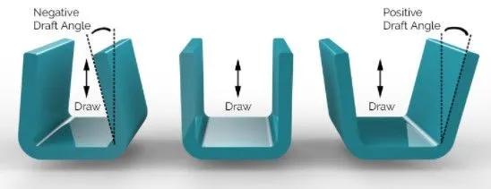
Types of surfaces involved
Class A surface
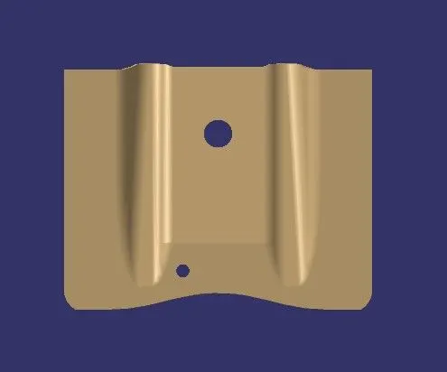
This is the input surface for the design engineers for designing the inner panels or features of the parts. It is the styling surface of the component which shows the outer appearance of the parts.
Class B surface
The thickened surface is called as B surface. It is also called as engineering surface. This surface contains all the necessary part feature like fillet, ribs, bosses etc.
Class C surface
The surface joining the class A surface and class B surface is called as C surface.
Tools used
- Multiple Extract
- Trim
- Un-trim
- Offset
- Extrapolate
- Boundary
- Sweep
- Join
- Smooth curve
- Close surface
- Intersect
- Publication
Steps involved in creating the Base Bracket
Tree structure
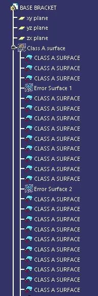
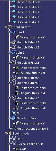
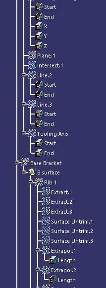
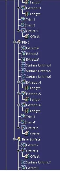
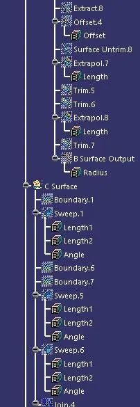
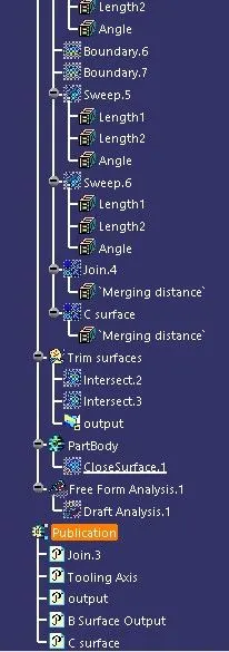
Step :1 Check the class A surface
The input class A surface is checked for any gaps or disjoints using the join or boundary commands.
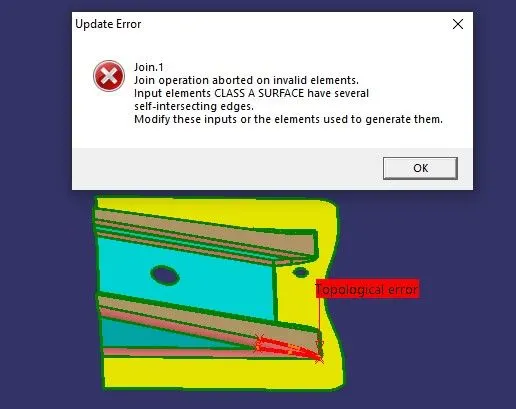
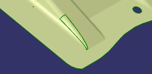
If there is any Minor error the it can be rectified or else send back to the Class A surface designer to make the necessary modifications properly.
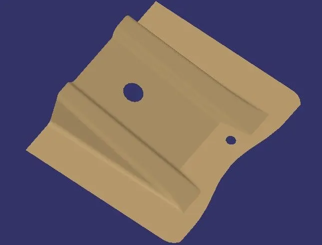
Step :2 Create the Tooling axis
ZX plane
If we check the inntersection of ZX plane on the class A surface we can clearly see that the all the surface can easily cleared in the tooling axis during ejection.
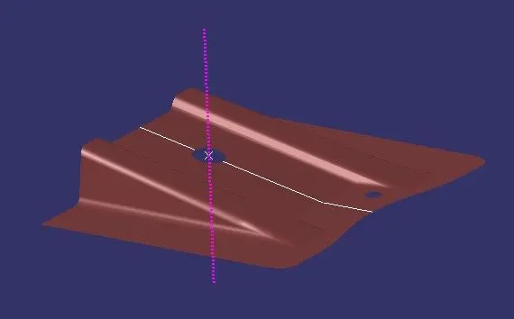
YZ plane
In the YZ plane we can check the tool axis clearance for the surfaces which may not clear the tooling axis line, by drawing normal lines along the surfaces(intersection points) and getting an bisecting line as the tooiing axis.
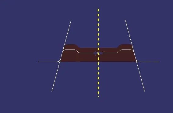
Bisecting line
The bisecting line is used to create a line bisecting the two reference lines created in normal direction. The bisecting lines helps us to achieve the average draft angle between the two reference lines.
Step 3
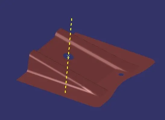
The tooling direction is created with the intersection of the normal lines in the YZ plane intersection.
Step 4
In the next step publish the tooling axis and Class A surface so that we can access it easily and use it for further creation of surfaces or thick body.
Draft Analysis
Step 5
Once the tooling axis is created the draft analysis can be done. For viewing the draft analysis results we need to change the view parameters into customise mode enabling only the material.
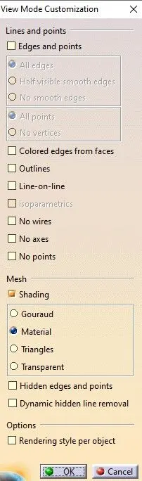
Go to insert-analysis-feature draft analysis.
The compass option is used to choose the tooling axis. The color coding shows the result of the draft analysis done. The limits of the draft angle can be changes according to the needs.
Types of the modes in the analysis
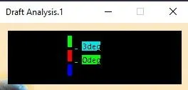
A single limt can be chosen to show the positive or negative draft
Multiple limits can also be set based on the requirements
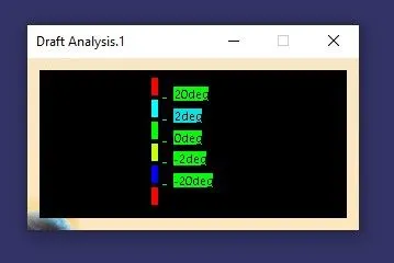
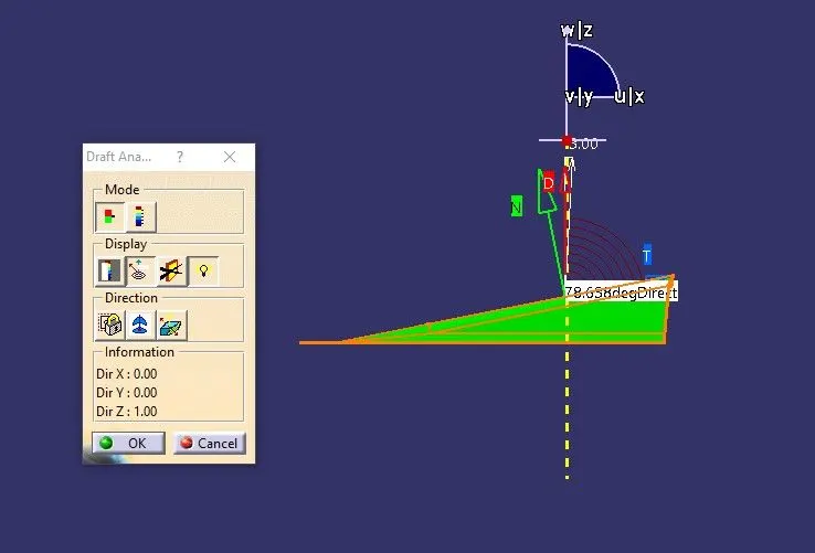
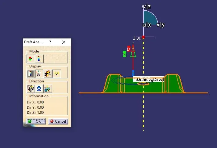
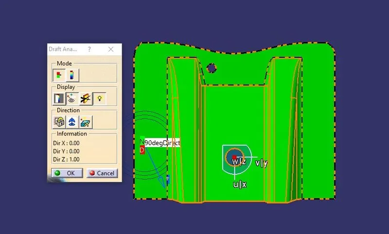
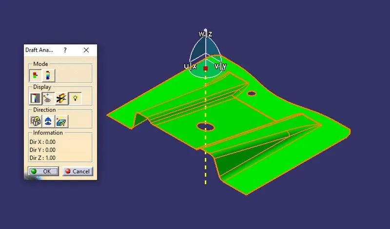
The draft angle value can be found at any given point of the surface. For this case 3 degree is chosen as the optimum angle and we can see that the entrire model has positive draft angle highlighted in green color. Zero draft angle would have been shown in red color and negative draft in blue color.
Side View
Front View
Top view
Isometric view
Step 6 Creating the Class B surface
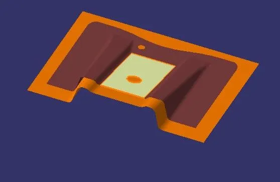
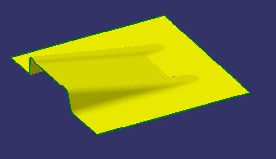
- The class B surface can be created by offsetting the Class A surface, for ease of design we can divide the surface into smaller portions and then work on them.
- The surfaces are extracted and then they are untrimmed and extrapolated to get the required intersections and the surfaces are trimmed off and offsetted according to the required thickness.
-
Fillet value
In order to maintain constant wall thickness Fillet value= Fillet value + wall thickness. The fillet value is added for the surface offsetted below and no surface offset or thicken should be made above the Class A surface since it is the most outermost styling surface
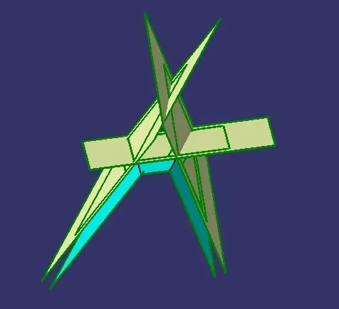
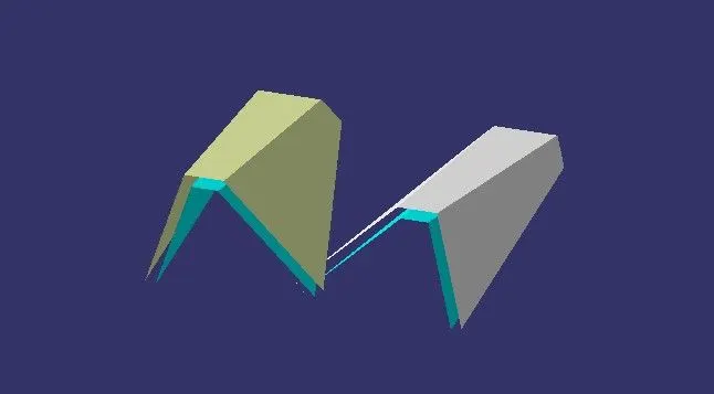
Ribs
Both the ribs are designed separately following the same steps and then trimmed with the base surface.

Base Surface
Step :7 Class C surface creation
The Class C surface is created by sweeping the extracted boundary of the Class A surface with respect to the tooling axis.
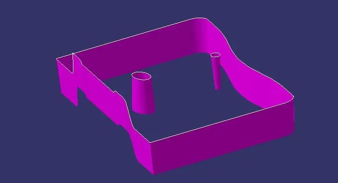
Then the Class A and Class C surface are joined together
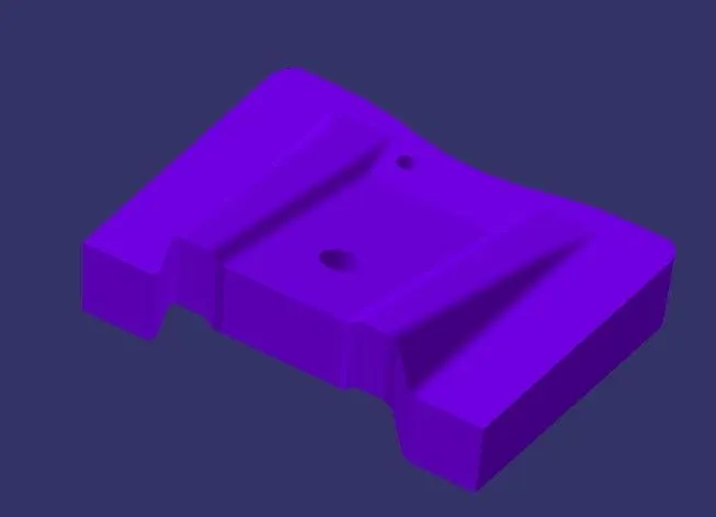
The join of the Class A and Class C surface is trimmed with the Class B surface to get the required output.
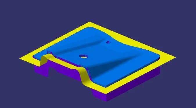
Output
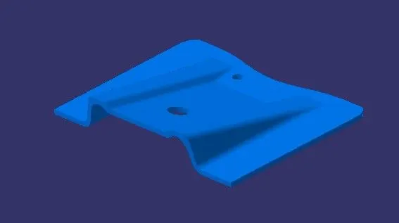
Then the closed surface command is used to make the solid body from the output surface
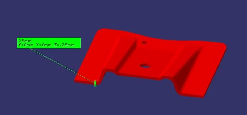
part images
Front view
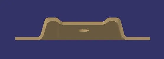
Side View
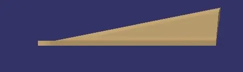
Top view
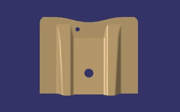
Bottom view
Conclusion
Thus the base bracket is created from the class A surface with the required thickness and the draft analysis is performed checking the required draft angle.