Week 11 - Final project
Aim
- To Create thickened(Closed Surface) part using master section.
- To Create the mounting features as per design guidelines used in the industry with master sections provided.
- To apply material to the parts
- To do the Draft analysis & Tooling analysis for each part
- To create parting lines and check tooling feasibility
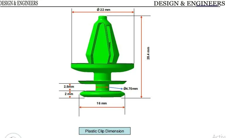
- To use Push pin with Dog house for Lower substrate to Door panel attachment
- To use heat stakes for part to part attachment
Introduction
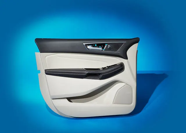
Door Trim
- A Door Trim is an interior component attached to the inner side of the door. This improves the appearance of the vehicle interior and also the vital module component that creates a more comfortable interior by providing a variety of accouterments and functions.
- Door panels were formerly made of cardboard with an upholstered interior finish of vinyl, leather, cloth, carpet, or other materials for the decorative trim. Modern cars typically have door cards made of plastic, most often using injection moulding, as well as incorporating other decorative materials.
- The door trim must be light weight and have high impact resistance.
Materials commonly used
- Acrylonitrile Butadiene Styrene(ABS)
- Polyvinyl chloride(PVC)
- Polypropylene(PP)
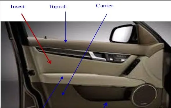
Door Trim Components
- Upper trim
- Applique
- Door Release handle
- Arm rest
- Switch Bezel
- Grab handle
- Speaker grille
- lower trim
- Map pocket
Design Methodology
Extract the the class A surfaces and insert the parts in the assembly and work by top down assembly approach.
Tooling Axis Creation
Tooling Axis is the direction in which the core and cavity opens. It must be chosen in manner where whole part can be ejected easily.
Check the class A surface
- The input class A surface is checked for any gaps or disjoints using the join or boundary commands.
- If there is any Minor error the it can be rectified or else send back to the Class A surface designer to make the necessary modifications properly.
The most suitable direction for tooling axis was found and the tooling axis was created for the respective parts.
Then the class B and class C surface are created and the Class A and C surface are joined trimmed with Class B surface to get the closed surface which is used to make the solid body
Tooling Axis
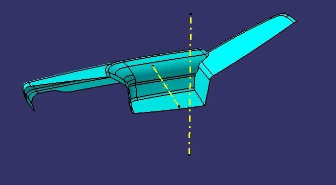
Arm Rest
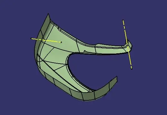
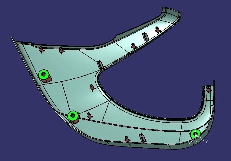
Lower Substrate
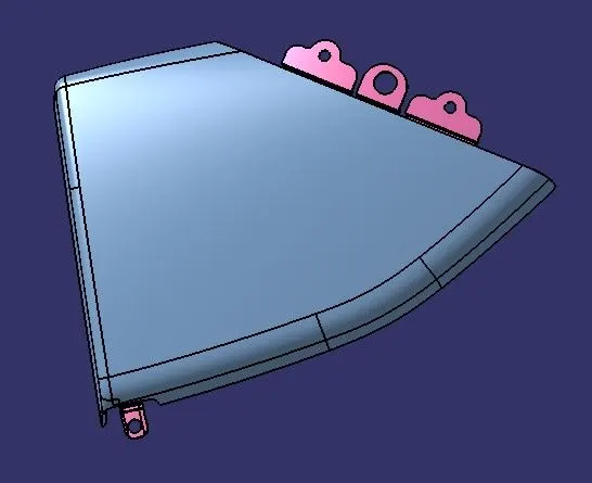
Map Pocket upper
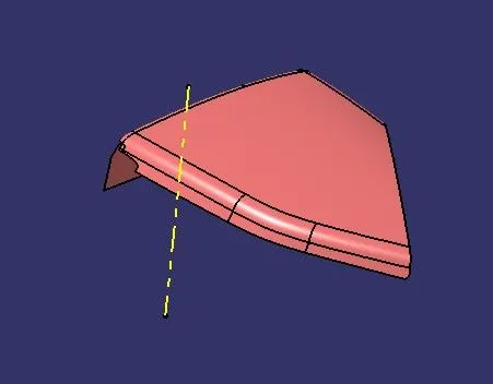
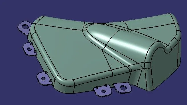
Map pocket Lower
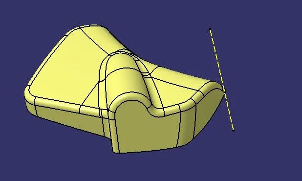
Draft Analysis
Once the tooling axis is created the draft analysis can be done. For viewing the draft analysis results we need to change the view parameters into customise mode enabling only the material.
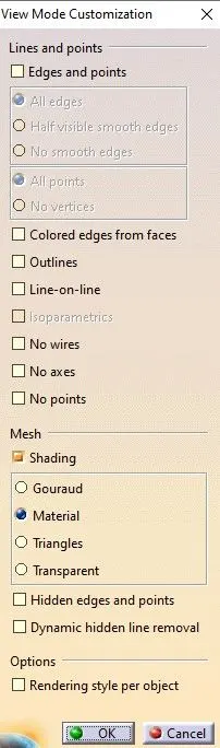
Go to insert-analysis-feature draft analysis.
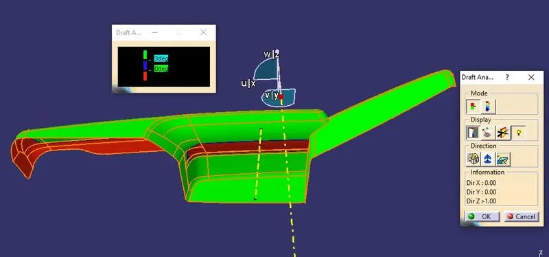
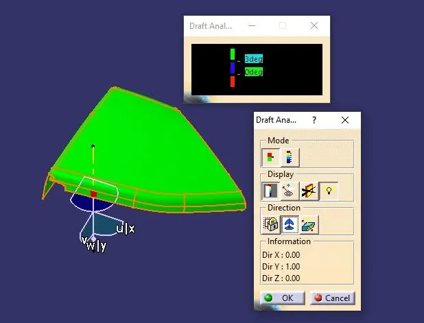
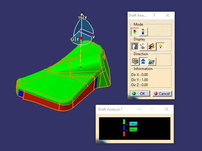
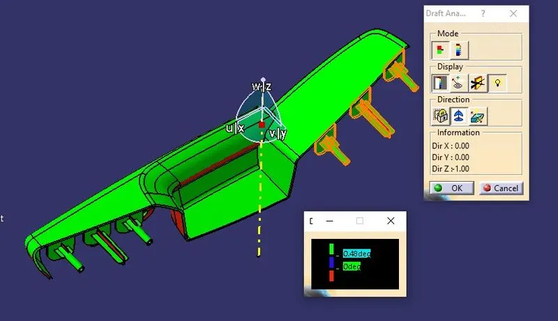
The compass option is used to choose the tooling axis. The color coding shows the result of the draft analysis done. The limits of the draft angle can be changes according to the needs.
Types of the modes in the analysis
A single limt can be chosen to show the positive or negative draft
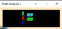
Multiple limits can also be set based on the requirements
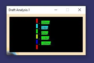
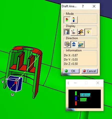
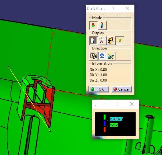
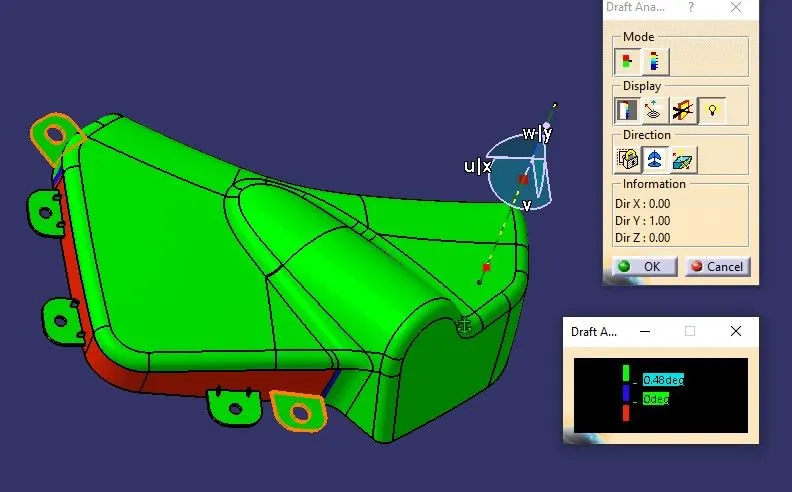
The draft angle value can be found at any given point of the surface. For this case 3 degree is chosen as the optimum angle and positive draft angle is highlighted in green color. Zero draft angle will be shown in blue color and negative draft in red color.
Draft Analysis
The regions/patches failing the draft requirement must be informed to class A surface designer and so that he can change it, or they can be manufactured as separate parts and joined or tooling axis has to be made complex to eject the part, but both are cost increasing solutions, hence it is better to modify the class A surface to clear the entire part in the main tooling axis.
Arm Rest
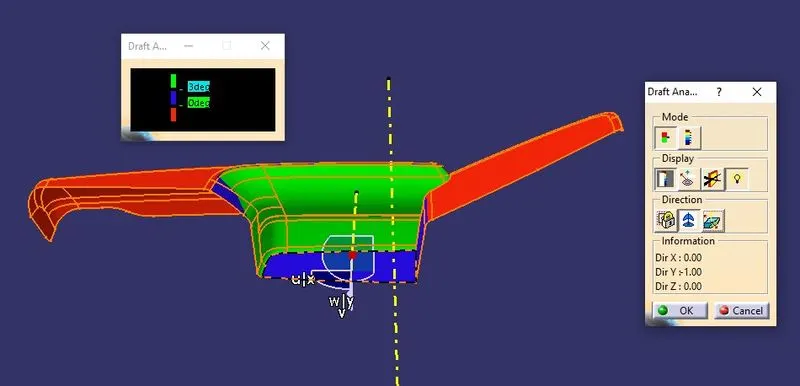
Lower Substrate
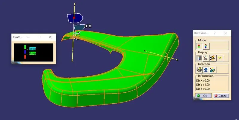
Map pocket Upper
Map pocket lower
Individual parts creation
Arm Rest
Class A surface
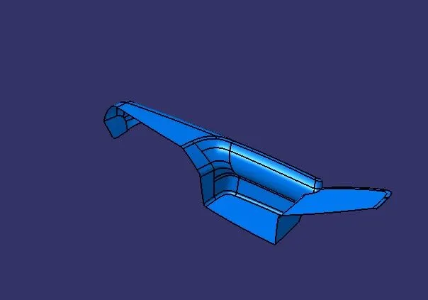
Class A and B surface
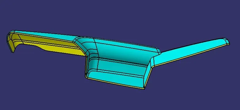
Class C surface
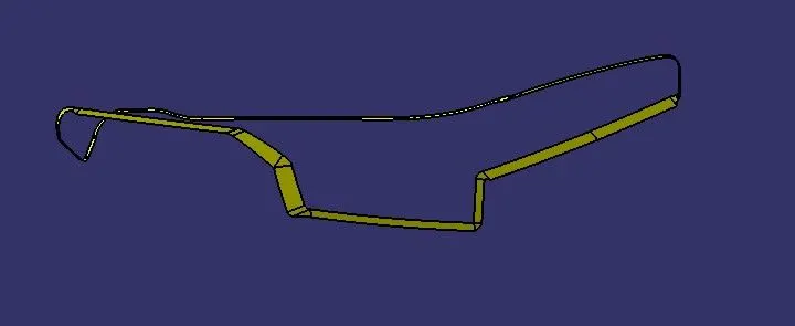
Class A and C surface
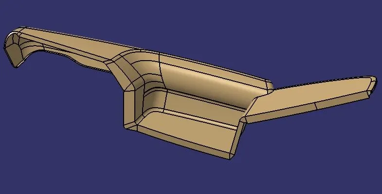
Closed Surface
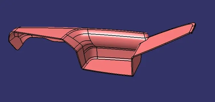
Lower substrate
Class A surface
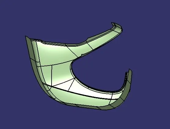
Class A and B surface
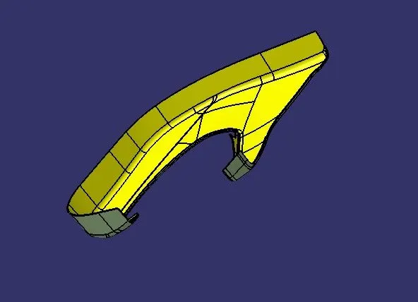
Class C surface
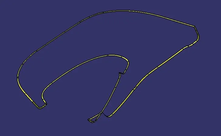
Class A and C surface
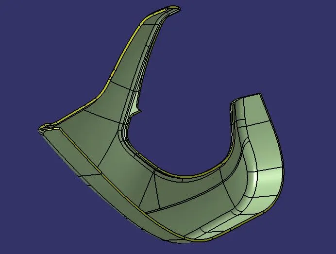
Closed Surface
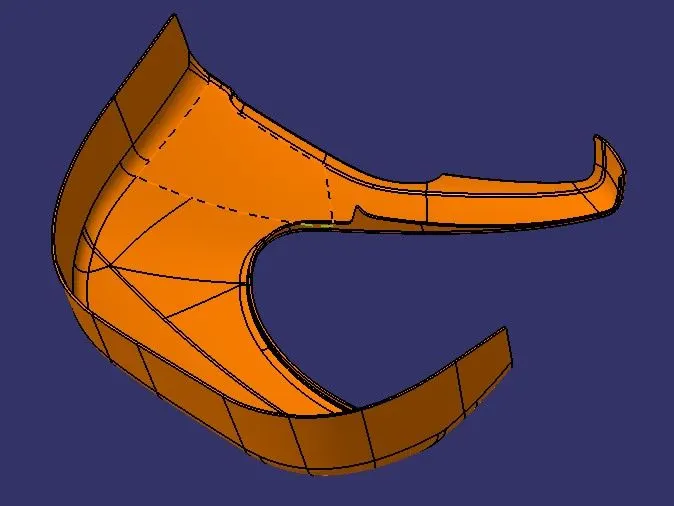
Map pocket upper
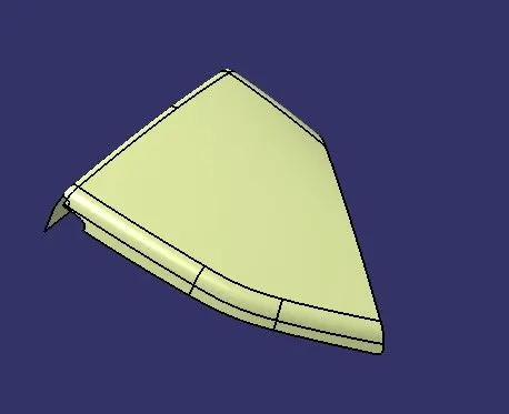
Class A surface
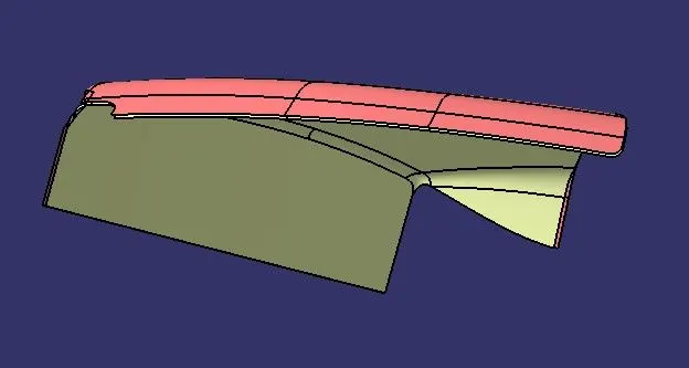
Class A and B surface
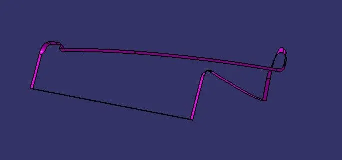
Class C surface
Class A and C surface
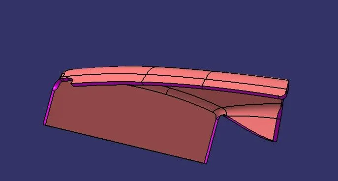
Closed Surface
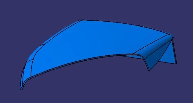
Map pocket Lower
Class A surface
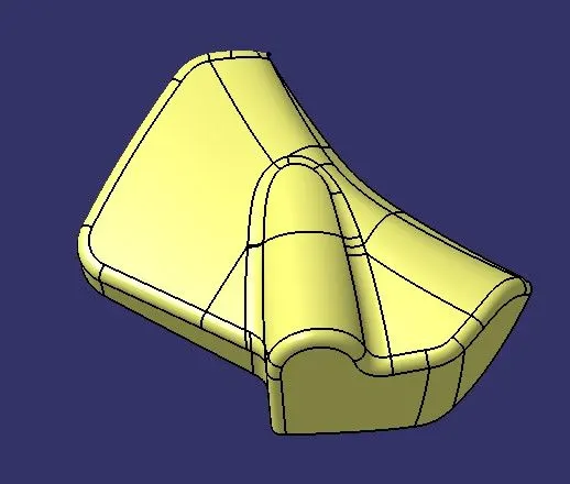
Class A and B surface
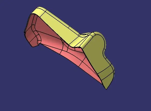
Class C surface
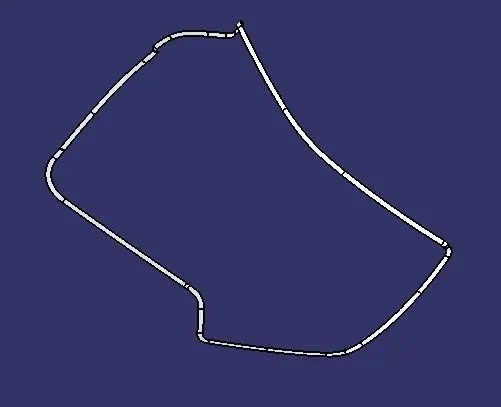
Class A and C surface
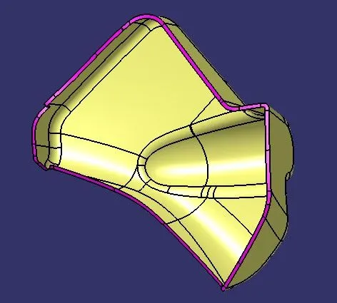
Closed surface
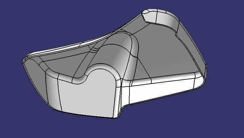
Engineering Features
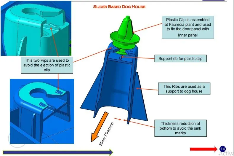
Dog House with push clips
Dog house
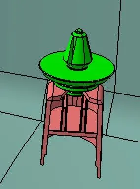
Dog house is an engineering feature used in plastic trim design. Dog houses are used as supporting feature. Doghouse is a embossment for screws to attach one piece of plastic to another one. For example, It can be used for adding garnish for the bumper cover.
Input
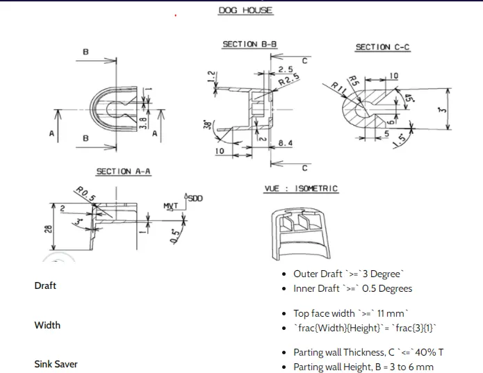
Draft analysis
Heat staking
Heat staking also known as thermoplastic staking is the process of joining two dissimilar materials together. In heat staking we use local heating and cooling to raise the temperature of plastic components and allow plastic reforming to be carried out.Heat Staking eliminates the need for extra hardware, which can become defective, break, or otherwise suffer from quality control issues.
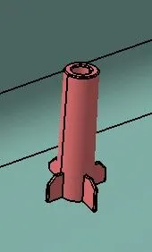
The minium of 0.5 degree draft should be provided and ribs can be attached to impart strength to the heat stakes.
Materials Used:- Polycarbonate (PC), Polypropylene (PP), Polystyrene (PS), Acrylonitrile butadiene styrene (ABS), Nylon.
Advantages
- Heat staking is done in one machine cycle.
- Heat staking is safe to use with a broad range of electronics and produces a higher pull strength versus the ultrasonic technique.
- very less Mechanical Vibration
Applications
- Heat staking LED Stamped Arrays or LED Flex Circuits into the plastic housings for OEM automotive and aerospace industries.
- Heat staking is also the preferred process in many medical device assembly applications for attaching adhesive patches to wearable glucose monitor devices and wearable medicine dispense devices versus the more brittle feel of an ultrasonic welded patch against the patient’s skin.
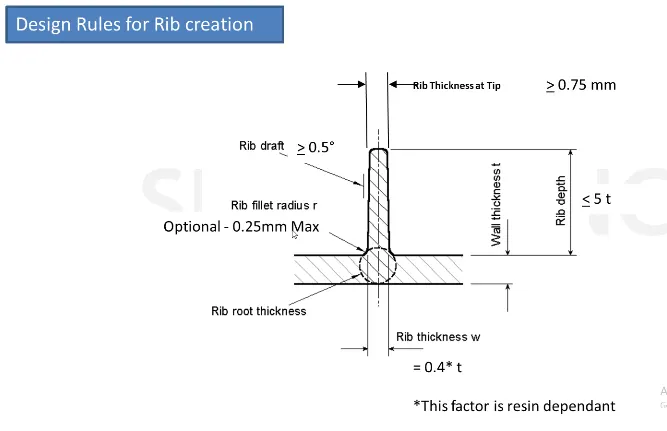
Ribs
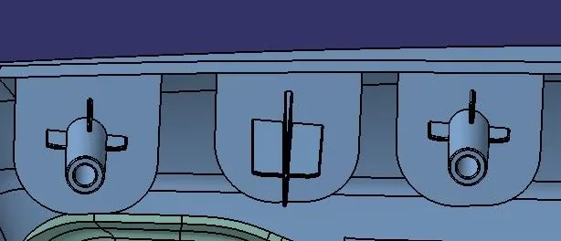
These are attached to provide strength to the bosses or heat stakes or the part itself.
Flanges
Flanges are designed according to the master sections to support and attach the engineering features.
Part Draft Analysis
Arm Rest
Lower substrate
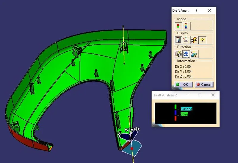
Map pocket upper
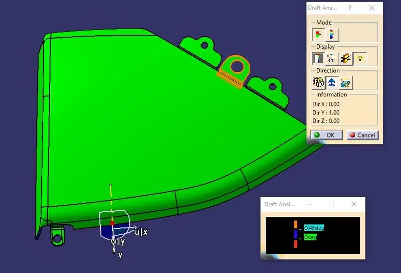
Map pocket lower
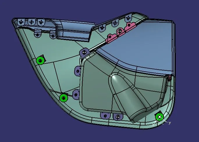
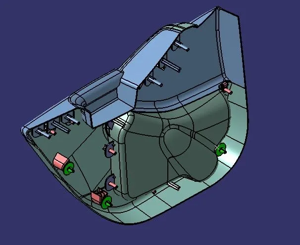
Part and Assembly Images
Arm Rest
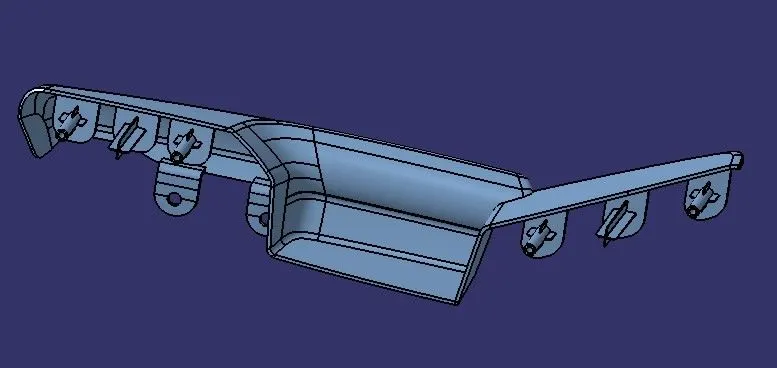
Lower Substrate
Map pocket upper
Map pocket lower
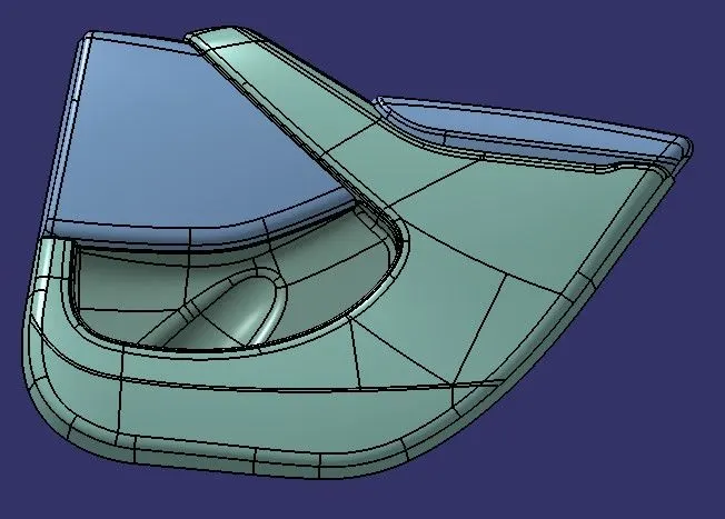
Assembly Images
Conclusion
Thus the door trim is created with required engineering features in Catia V5.