Week 3:- BiW Fixture Design Methodologies Challenges
BIW Fixture Design Methodolgy
1.Design Methodology
Design methodology is the study of the principles, practices and procedures of designing. It is a process of analysis, synthesis and evaluation.
Types of design methodologies
Top Down Design or Stepwise Refinement
In this the end solution is known and works is carried out backwards, refining each step along the way.
Bottom Up Design
This methodology starts with a foundation and works up towards a solution.
Structured Design
This is an industry standard. The technique starts by identifying inputs and desired outputs to create a graphical representation.
Structured Analysis and Design Technique
This approach utilizes a diagram to describe the hierarchy of a system's functions.
Data Structured Systems Development
Data structure determines the system structure in this methodology.
Object Oriented Design
This methodology is based on a system of interacting objects.
Design methodology used for a BIW fixture design
It is the pre-design process carried out during the concept development phases in fixture design
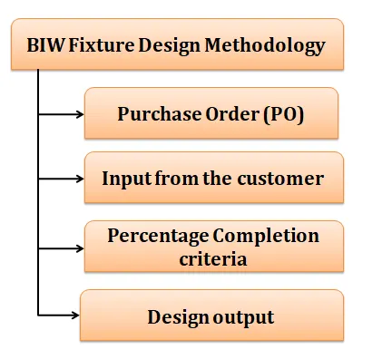
Step:1 Purchase order(PO)
A purchase order is a contract between the buyer and the seller and it gives specific information like product or services to be delivered, delivery date, and any other terms and conditions
including the price. The purchase order is also called as ‘PO’.
Stages involved in PO
Stage 1- Purchaser creates purchase requisition.
Stage 2- Purchaser issues purchase order.
Stage 3-Vendor approves rejects, or submits PO for discussion.
Stage 4- Purchaser records purchase order planner.
Details mentioned in PO
- Description of the products that are ordered
- Quantities of the parts(kg, meters, numbers etc.,)
- Price at the time of order
- Name of the vendor to whom the purchase order is being sent
- Shipment address.
- Billing address of the company
- Terms and conditions of payment.
- Due date of delivery/consignment.
Step:2 Input from the customer
The input given by the customer serves as the starting point for the design team. The customer gives all the specifications and standards that has to be considered while designing the
fixture. From the customer input the scope of the work is evaluated and the necessary processes like design, analysis, testing, GD&T etc. are carried out.
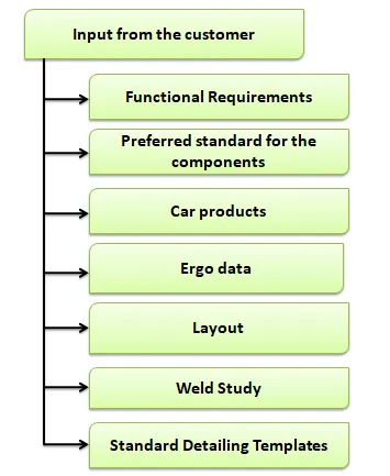
The common input given by the customer includes
- Functional requirement of the fixture(Hemming/checking/storage fixture)
- Preferred standard components.(Eg. ABB, NAAMS, ZYTRAn etc.)
- Ergo data for the operator (safety zone, loading unloading height etc)
- Layout of the assembly line.
- Car products(3D, 2D CAD files, PLP points, clamp plan, risers etc.)
- Weld study (Type and number of welds, type of gun etc.)
- Standard detailing templates.
Step:3 Percentage Completion Criteria
It is the criteria used in design and dispatch phases of the BIW fixture.It is used to check the progress of the project based on the percentage of work completed.
For example
Input and concept design - 0-25%
Concept approval and simulation - 25-40%
Design finalization and detailing - 40-85%
Testing and dispatch - 85-100%
Step:4 Design Output
The design output comprises of 3D models and 2D drawings of the tools.
There are two types of tools
Unitized tools
They have multiple units on a common base. They are represented in two kinds of sheets.
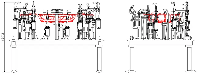
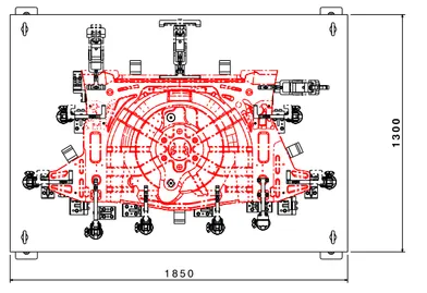
Layout sheet- It is a detailed drawing of individual units including all the components.
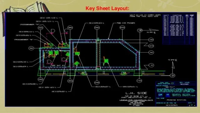
Key sheet- it is an index of units and their placement on the tool base.
Non-unitized tools
These are stand alone units and are detailed completely on a layout sheet.
2. Inputs required from the customer to start designing a Fixture
The input given by the customer serves as the starting point for the design team. The customer gives all the specifications and standards that has to be considered while designing the
fixture. From the customer input the scope of the work is evaluated and the necessary processes like design, analysis, testing, GD&T etc. are carried out.
Functional requirement
It defines the usage of the fixture. It could be used for welding, Hemming or Checking fixture. Depending on this the design considerations are taken in to account while designing the
fixture.
Preffered Standards
The standard pre-available parts are frequently used in fixture design. These standard parts saves our project time and money. These are the standard for fixture design parts ABB,
NAAMS, TUNKERS, ZYTRAN, DESTACO.The standard parts like riser. L-Blocks Retainers,Clamps, Cylinders, Switches, Sensors etc. can be used if they meet the requirements
Car Products
- GD & T
Geometric dimensioning & Tolerance of the part for which the fixture have to be designed. GD & T provides information about Locating pins, Rest, Clamp, Dumps and slides information of
each station and Sequence & opening of clamps, Dumps and slide stroke information.
- Part List
This is the list of part which are going to assembled in the fixture. It includes information about the part name, Part number,Tooling revision, Part thickness etc.
- Cad files of part
The 3D model file of the car part designe by using modelling software is given from the customer.
- Clamp plan
This is the clamping plan of the part whicle doing the operation. We can not change th eclamp plan without the permission of the customer. Itis very important input from the customer. It
provides location of pins, Rest, Clamps, Dumps etc.
- Product assembly process sheet
It gives detail process of the completion of the part from scratch to the finished product assembly.
- Layout
Layout gives information about Flow of parts, Station pitch, Robot stations, Tool changers, Tip dressers, Platform height, Sub asselmbly links & loading/Unloading sequence.
- Ergo Data
It is the study of human behaviour & movements during the assembly work. It provides data regarding loading and unloading height, working safety zone of the operator etc.
- Weld study
This gives the information of the type of weld gun required which also depends on the size and thickness of the part etc. It also gives details of the weld matrix and the weld point
positions. The geo weld point ensures the geometry of the assembly and the Re-spot weld points adds strength to the already welded point.
- Standard detailing templates
Every customer have their standard of detailing & the templates which are used for 2D drawing & detailing.
3. Input obtained from Car Products
GD&T
GD&T provides information and also help to calculate the clearances for locating pins, rest, clamp, damp & slide unit information of each station Also includes the information of sequence
of openings of clamps, dumps & slide stroke information. GD&T is also essential for stack up analysis.
Parts list
It gives the lists of parts which are needed the fixture assembly. The list contains the information of part number, part name, quantity, revision of fixture, part thickness, etc. It helps the
operator to indentify and assemble the parts correctly.
CAD files
The 3D model of the car parts is provided by the customer. This helps the designers to start fixture design process and do the further developments. The 3D cad files could be in the format
of step file (stp) or IGES file based on the requirement. The CAD files are used in the fixture assembly.
Clamp plan
Clamp plan provides the information of location of pins, Rest units, clamp unit, dump etc. It is the important input from customer. Any changes in the clamp plan must be done with proper
communication and consent of the customer.
Product assembly process sheet
It gives the details about the stages wise assembly process like how the parts move from one assembly process to other after the completion of joining process.
4. Clamp plan
Clamp
A clamp is a device which is used to hold or secure objects tightly together to prevent movement during the fixture operation.
Functions of a clamp
- A clamp must hold the workpiece rigidly at the desired position.
- The clamp must be fast acting and clamp the workpiece in minimum time.
- The clamp must be able to resist forces and vibration.
- No scratch marks should be left on the workpiece.
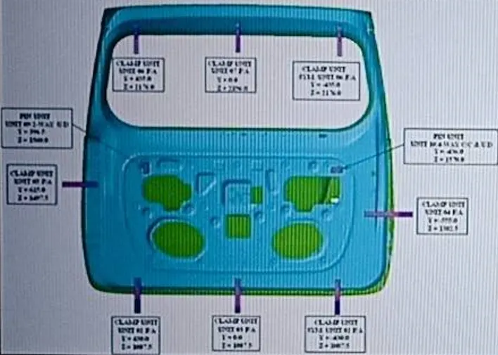
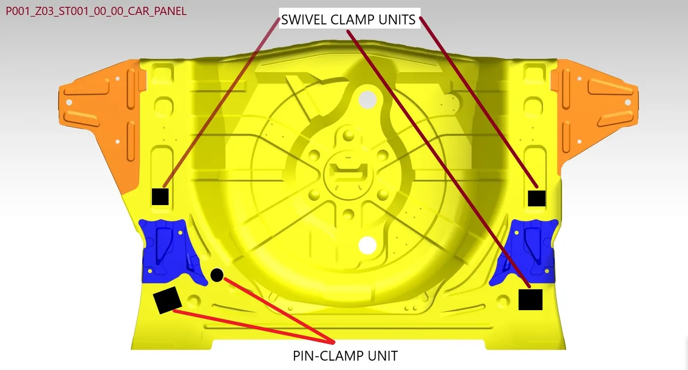
Clamp plan
The clamp plan provides the information of location of pins, rest, clamp units, Dump etc. The customer gives the location where the clamps can be located based on the design intent of the
part so the position of the clamp should not be changed without commmunicating to the customer. This plan gives the exact position of the camping units by mentioning a co-ordinates the
particular position.
5. Purpose of a layout
Layout
It is defined as plan for the effective arrangement of facilities and resources for optimum utilization of machines, processing equipment and maintenance departments. The layout is laid
inorder to achieve the proper usage of Men, Materials, Machines in a plant.
Plant layout is a floor plan showing the arrangement and the design of machinery and equipment of a plant. A good plant layout enables the quickest flow of material, at the lowest cost
and with the minimum handling to the complete processing of the product, from the receipt of raw material to the shipment of finished product
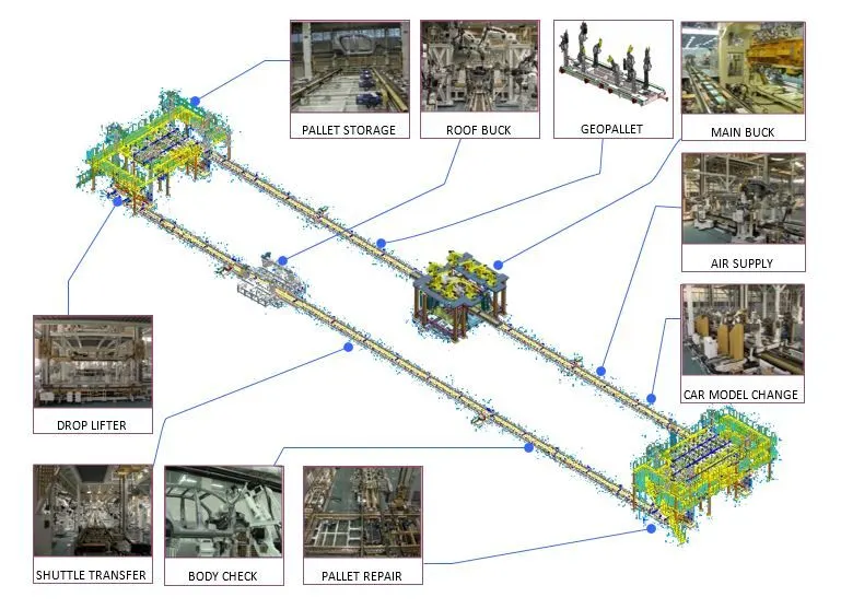
It the position of objects like robots, Fixtures, Racks etc. It shows the zone of reacheability for the robot used for the fixtures it is also called as the swept area of the robot. It is decided
based on the space available for the fixture.
Layout marks the area required for flow of parts, Station pitch, Robot stations, Tool changers, Tip dressers, Platform height. It also provides details on the Sub assembly links, loading and
Unloading sequence for the various operations.
Purpose of a layout
- Show the flow of parts in the assembly line
- To show the Station arrangement and distance between them.
- Highlight the position of Robot stations
- Give details on accessories like tool changer and tip dresser and their changing location.
- Sub assembly links
- Loading and unloading sequence of the parts
- To show the Platform height and operator ergonomics.
A layout of car assembly line
6. Ergo Data
Ergonomics
It is defined as the study of people's efficiency in their working environment. The goal of ergonomic study is to eliminate discomfort and risk of injury due to worker.
It also focusses on improving the efficiency of the operator. It helps to design machinery that is safe for operator to operate.
This data helps to design systems which require less effort by the operator and aid the operator to maintain the proper posture while working.
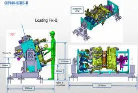
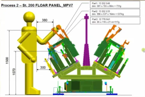
A ergonomic working condition
7. Weld study
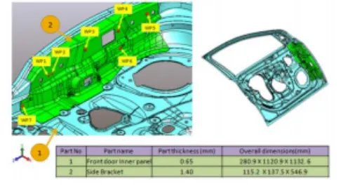
It is study that gives the information on the type of weld gun required for welding a part and it depends on the size and thickness of the part etc. It also gives details of the weld matrix
and the weld point positions. The automatic or semi-automatic weld guns are used. MIG welding is usually applied for joining of structural aluminium components, extrusions, castings and
sheet upto 2 mm thick.
Types of spot welds
Geo spot weld
The geo weld point ensures the geometry of the assembly the
Respot spot weld
Re-spot weld points adds strength to the already welded point. These are the weld points that were not completed during the geo weld.
Selection of weld gun
It is based on the following factors
- Type of weld required.
- Number of spots to be done.
- Type of current(AC/DC) required.
- Patch of gun travel.
A picture showing weld matric and weld points- geo spot weld in red and re-spot weld in green.
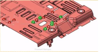
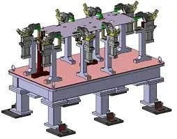
Weld study of a car panel
8. Criteria for percentage completion in the designing stage
It is the criteria used in design and dispatch phases of the BIW fixture.It is also used to decide the timeline and schedule of the project. It is used to check the progress of the project
based on the percentage of work completed. It shows the current status of the project and duration for completion of each task.

For example
Input and concept design (0-25%)
This stage includes the point from where the customer input is received and the concept design of the fixture is created.
Concept approval and simulation(25-40%)
The design concept is sent to the customer and asked for his approval and then the simulationn of the fixture is done.
Design finalization and detailing (40-85%)
If the customer is satisfied with the concept design and the simulation meets the required design intent, then the detailing works like layout, key sheet, drafting of the parts are carried
out.
Testing and dispatch(85-100%)
After the assembly of the fixture and quality inspection, the testing is carried out if the results are satisfactory then the fixture is packaged and dispatched.
9. Output in design
The design output comprises of 3D models, 2D drawings of the tools, Bill of materials. It has the drawing and specifications required for the component manufaturing.
The 3D files and 2D drawings are given to the customers in their required format and the key sheet, detailing of the parts has to be done in the standard template given by the customer.
Unitized tools
They have multiple units on a common base. They are represented in two kinds of sheets.
Layout sheet- It is a detailed drawing of individual units including all the components.
Key sheet- it is an index of units and their placement on the tool base.
Non-unitized tools
These are stand alone units and are detailed completely on a layout sheet.
10. Design tree structure and its significance
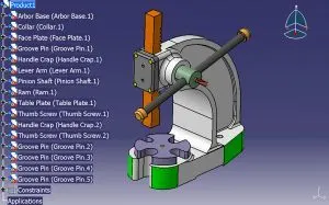
The tree structure is also known as design tree, feature tree, or history tree.It shows all the individual features in the CAD model are connected hierarchically, creating a network structure
where every node represents a feature and every connection represents a dependency between two features. It shows all the features, sketches, parts used to design a product. It also
helps the designer to locate any used design object within the design file.
A well organized structure is useful for
- Identifying or finding a specific part, tool or unit in the assembly.
- A well strutured design tree helps to eliminate the errors during design study, manufacturing, assembly and quality inspection.
- If the parts or assemblies are not properly or the design tree is not structures properly. it will create confusion to understand the design & may create major possibilities of making an error.
- Naming of a fixture or a unit or a part gives the information as to which project or zone or assembly do they belong.
- It can help us to identify the quantity of items of same type or differnet types are being used in assembly.
- Under the product there are main assemblies, Sub assemblies, designed part, Standard parts etc. these all parts are provided with specific numbers, Zone etc to identify them easily.
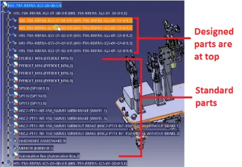
The above figure shows the design tree structure in which designed parts are at top and all the standard parts are at bottom
The number highlighted in blue denotes different things
H1L-T9A-RRFRA-JG3-00-00-00
H1L-T9A- The project name
RRFRA-Panel name
JG3- Jig number. 3
00- Unit number.
00- part number.
00-Component number.
11. Types of Units
Unit
A unit is a device has a specified function, especially one forming part of a complex mechanism.multiple units are joined together in order to form a fixture and are attached to a common
base,which serves as a common support to the units where they are fixed.
The BIW fixture is made of multiple units each serving a different function and purpose.The units are classified into two types
- Unitised tools
- Non unitised tools.
Unitised tools
Unitized tools are part of multiple units or multiple tools inside a BIW fixture.These are the tools which has to be represented by two formats i.e. Key Sheets and Layout
Sheets.
Simple units
Rest unit
Rest unit is basically a unit where the component is tested,there is no upper clamp to it.theere is no force applied to it.There is no cylinder attached to 'usually it will have a riser, a blade
and few rest mylers.
Fixed pin unit
It is a non-movable locating unit. It is used to locate the part quickly and correctly.
Retract pin unit
It is a movable pin unit and it can be up and down by using a retracable pneumatic cylinders which can be retraced to a certain distance.
Rough Locators
Rough locators are used to help the operator to locate the workpieces in the automated process.
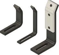
NAAMS Rough locator
Sensor unit
The sensor unit is used to ensure that the correct parts are assembled at the correct place. For example- If a assembly has 10 components then each part will have a sensor or multiple
attached to it to ensure that all the required components are attached.
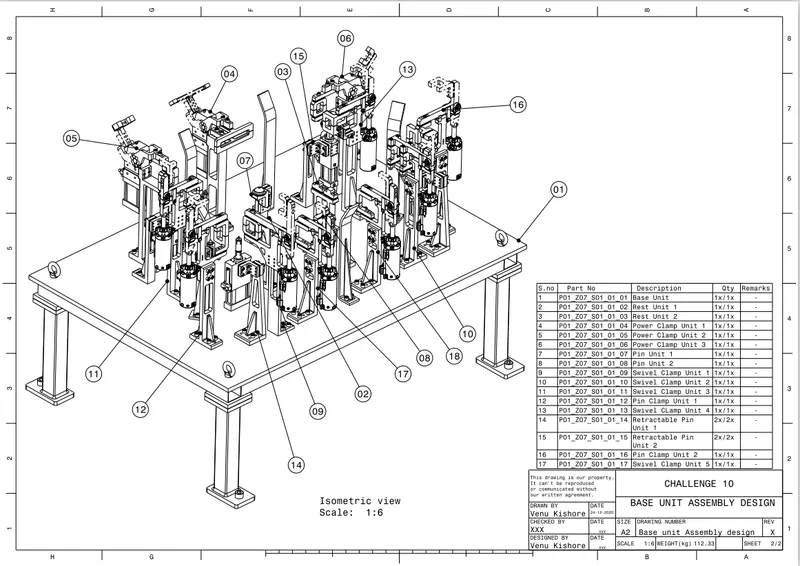
Base unit
A base unit is a unit where all the other units are assembled.
Parts of the base unit
Complex units
The complex unit is used in addition with the simple units for specific purposes.
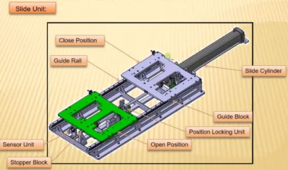
Slide unit
The slide units comprises of the sliding mechanism involved used in the fixture. It is used when there not much floor space available.
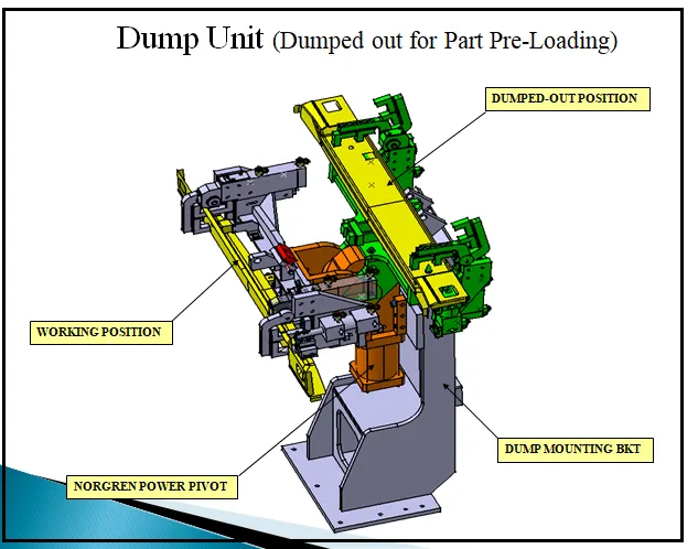
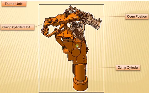
Dump Unit
Dump units are used when we can not use normal units like clamp unit, pin unit etc. due to some space constraints. It contains the dump cylinder, riser & blade should have enough
strength to bear the load of the cylinder and all the units.
Non-Unitized tools
Non unitized tools dont have any process functonality they are just used to store the components like grippers turntable, stands, etc.
Example- Stands, take out trolleys, Conveyor ,Turn tables, and gripper.
12. Fixed pin units and its purpose
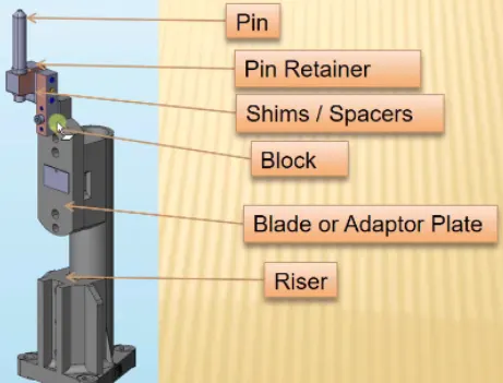
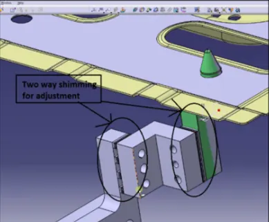
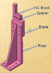
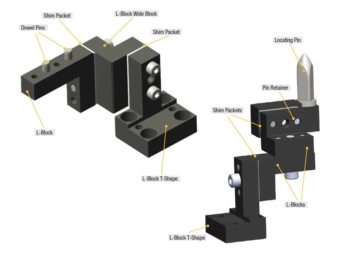
Fixed pin unit consist of riser, blade, block, shims or spacer, pin retainer & pin.The Riser is the standard part which is used to rise up the height of the while unit. Blades are plates mounted
on the riser. Other parts like cylinder, arms etc are mounted on the blade. Shims also known as spacers comes with the thickness of 0.1mm. 0.2mm. 0.5mm etc and used to compensate
the stackup tolerance which reflects at the panel holding part called Mylars. In fixed pin shims are used to adjust to traslational motions. Pin retainer will support the pin & the locating pin
which restricts movement of the car panel.
Purpose of fixed pin unit
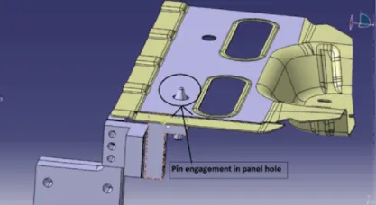
Fixed pin unit is a unit designed to locate the car panel using pin. The fixed pin unit uses the 3-2-1 principle. It restricts 6 degrees of freedom of the car panel. If 2 pins are used to locate
car panel one pin must arrest 4 way (4 translational ) and the seconf one must arrest 2 way (2 rotational ) of a car panel.
13. Parts of a fixed unit
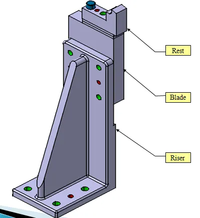
Riser
Riser is a structure generally used to mount the toggle clamp and rest, clamp mylars and location pin. It is not necessary to have one riser where all the parts of clamp or rest or location
units are mounted. Generally risers are either made of plate fabrication or plate and tube welding together or from single gas cut plate. These are generally manufactured to give height to
the assembly.
Blades
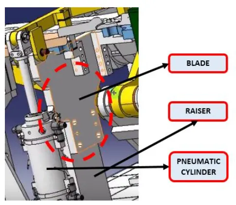
The blades are plate like structure attached to the riser. The parts like the cylinder, arms, raiser etc are mounted on the blade. The chamfer is provided on the blade to strengthen the
blade.
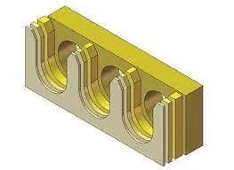
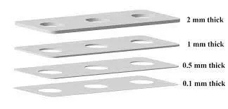
Shims
Shims are typically used in order to support, adjust for better fit, or provide a level surface. Shims may also be used as spacers to fill gaps between parts subject to wear. Shims are the
small parts which comes with the thickness of 0.1mm,0.2mm,0.5mm,1.0mm etc.
Pin retainer
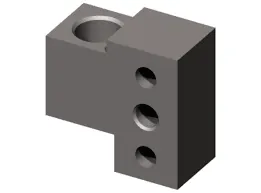
pin retainers are blocks made specifically for NAAMS locating pins. They retain the desired location of the pins during the automation process.
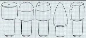
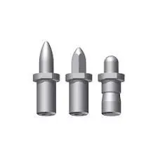
Locating pin
locating pins are used for controlled, fine tolerance positioning of a work piece. Usually two locating pins are enough to properly locate the work piece on one plane.There are dozens of
styles of locating pins that can be utilized in a design. Locating pins are a great way to make sure the parts you are putting together fit the way you want them to fit. Drill two holes
opposite each other in each part, install a cylindrical locating pin, parts are aligned exactly the way we want. If we are having alignment issues with using just bolts or other fasteners, a
locating pin can be a great way to firm up our assembly.
14. Rest unit and its purpose
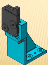
Nc blocks/Mylars
Mylars are the part which are holding the panel from top & bottomit is a jaw type.during welding it wont deforms from its position.lt is also known as fingers. lt wont allow the deformation
of the part due to welding stresses.
Mylars are of two types
- Clamping mylars
- Resting mylars
Only resting mylars are seen in resting unit.The panel which rests on the part is known as resting mylars.
Riser
Riser is a structure generally used to mount the toggle clamp and rest, clamp mylars and location pin. It is not necessary to have one riser where all the parts of clamp or rest or location
units are mounted. Generally risers are either made of plate fabrication or plate and tube welding together or from single gas cut plate. These are generally manufactured to give height to
the assembly.
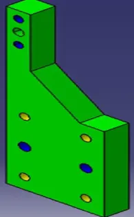
Blades
The blades are plate like structure attached to the riser. The parts like the cylinder, arms, raiser etc are mounted on the blade. The chamfer is provided on the blade to strengthen the
blade.
Shims
Shims are typically used in order to support, adjust for better fit, or provide a level surface. Shims may also be used as spacers to fill gaps between parts subject to wear. Shims are the
small parts which comes with the thickness of 0.1mm,0.2mm,0.5mm,1.0mm etc.
15. Fundamentals of the sensor unit
Sensor is a device which detects or measures a physical property and records, indicates, or otherwise responds to it. It is a unit designed to sense car panel postion and orientation using
electrical sensors. The information/signals from the sensors is send to the PLC to process the signal and give the required output signal. Commonly used sensors are proximity sensor, laser
sensor, photo electric sensor, Infrared sensor etc.
sensor unit design fundamentals
- Every single loose panel which are being welded in a tool should be sensed. The assembly of car panel consist of number of panels. The location of every panel is fixed. There are some locating units, clamping unit,rest unit etc, are provided for proper location and operation. The sensor is attached in this unit to sense the part is loaded or not. If the part is not loaded the sensor will send negative signal to the PLC controller and operation will not start and viceversa. Hence every single loose part should have at least 1 sensor.
- Each panel should be sensed by 1 to 2 sensors depends on the size of panel, Preffered location of sensors to be in diagonal opposite ends of panel. sensor is used to sense the part is loaded or not and starts the operation by sending the positive signal and vice-versa.
- Every sensor should be mounted in such a way that is can be adjusted in 3 directions.
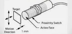
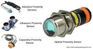
Proximity sensor
A proximity sensor is a sensor able to detect the presence of nearby objects without any physical contact. A proximity sensor often emits an electromagnetic field or a beam of
electromagnetic radiation (infrared, for instance), and looks for changes in the field or return signal.
Inductive proximity sensors operate under the electrical principle of magnetism when a fluctuating current induces the voltage in a target object. The inductive proximity sensor contains
certain type of solid-state control system. It contains an oscillator circuit that generates a high-frequency magnetic field
Thus the proximity of the object is detected by a change in capacitance. The sensor can also be used to detect a wide variety of non-metallic and metallic objects and typically operate over
a range of 3 to 30 mm.
- Inductive Proximity Sensor.
- Optical Proximity Sensor.
- Capacitive Proximity Sensor.
- Magnetic Proximity Sensor.
- Ultrasonic proximity Sensor.
Photoelectric sensor
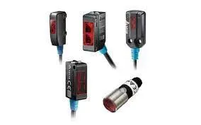
A photoelectric sensor is a device used to determine the distance, absence, or presence of an object by using a light transmitter, often infrared, and a photoelectric receiver. They are largely used in industrial manufacturing.
A Photoelectric Sensor consists primarily of an Emitter for emitting light and a Receiver for receiving light. When emitted light is interrupted or reflected by the sensing object, it changes the amount of light that arrives at the Receiver. The Receiver detects this change and converts it to an electrical output.
There are three major types of photoelectric sensors: thru-beam, retroreflective, and diffused. Each sensor has its own strengths and can be used in a variety of ways.There are three major types of photoelectric sensors: thru-beam, retroreflective, and diffused. Each sensor has its own strengths and can be used in a variety of ways.
Checking objects on production lines or conveyors: photoelectric sensors can detect items' sizes to spot any errors, or simply spot their absence, as well as picking up problems like misaligned caps on bottles. They are widely used in the food and pharmaceutical industries, and in packaging plants.
Laser Sensors
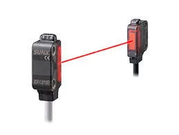
A laser sensor is a measurement value recorder working with laser technology and turning the physical measured value into an analogue electrical signal. This means that the laser sensor
is conceived for contactless measurement.These sensors are integrated in a point laser or a line laser. Laser sensors generally work well in a dirty environment since the focused light can
“burn” through dust. The focused beam also enables long sensing distances, and detection of small objects or targets through small openings. Laser sensors are often used in process
monitoring and closed-loop feedback control systems.
The laser emits a laser beam to the target. The light reflected off the target is concentrated by the receiver lens and forms an image on the light receiving element. When the distance
changes, the concentrated light reflects at a different angle and the position of the image changes accordingly.
- Laser distance sensors.
- Displacement sensors.
- Laser projectors.
- Laser light curtains.
- Laser photoelectric sensors.
- Positioning lasers.
- Laser edge detection sensors.
16. Rough locator unit and its design fundamentals
Rough Locators
Rough locators are used to help the operator to locate the workpieces in the automated process.
NAAMS Rough locator
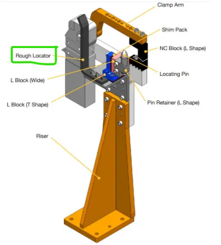
It is used a fool proofing method, because due to the rough locator part cannot be located in incorrect position. The rough locators are set according to the respective pancl. Hence the part
can only be loaded in defined direction and orientation.
Fundamentals of rough locator design
- Rough locators should be placed at the edges of the car panel which it has to guide.
- It must be placed at the same angle of the car part edge with a minimum distance of 2.5mm from the edge of the car part.
- Rough locator should guide the panel in the pin arresting direction.
- Rough locator should guide the panel before 10-15 mm to start of the pin engagement.
- It should have entry angle for the car panel in the range between 30-45 degree.
- Rough locator should be designed with two slots to mount the easy adjustments The locators should be in the direction of car part guiding.
Base unit
A base unit is a unit where all the other units are assembled.
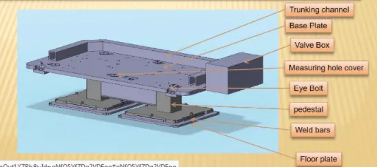
Parts of the base unit
Parts of Base unit
- Valve box
- Base plate
- Trunking channel
- Hole measuring cover
- Eye bolt
- Pedestal
Base plate
It is a flat plate or frame which supports the base of the column and distribute the column weight and stress and stabilize the fixture. The number of mounting holes are drilled to
assemble the other parts and units. It could be made of steel or aluminum based on the application. The base plate can be 25 to 40mm thick.
Valve box
Valve box supplies air to all the pneumatic cylinders assembled in the fixture. It consist of solenoid valve which collects the air from the pneumatic cylinders. The pnuematic powered
fixture works on the air pressure given from the valve box.
Trunking channel
Trunking channel is a kind of cable duct, which helps to guide and protect the wirings/ tubes used in the fixtures.
Hole measuring cover
The coordinates points are engraved on hole measuring cover. This hole gives the coordinates which serves as a reference placements of other units. This co-ordinates helps in CMM and
QC inspection.
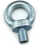
Eye bolt
An eye bolt is a bolt with a loop at one end. They are used to firmly attach a securing eye to a structure, so that ropes of cables may then be tied to it for lifting purpose. Eyebolt is used
to lift the base unit while relocating.
Pedestal
Pedestal stand like structure where the entire unit of the base will be mounted.
Floor plates
Floor plates is used to mount the base with floor. It also helps to achieve the flat mounting of the fixture.
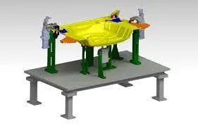
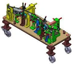
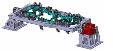
Types of Base unit
Fixed type
Moving type
Rotating type
18. Dump unit and its functions
Dump unit is a type of complex unit. It is used when there is less space available and have fit all the part in it. It consists of clamp unit, pin unit attached panel will be assembled. It has
dump cylinder and complex design.The dump cylinder performs the operation of clamping and unclamping of the car panel. more than one cylinder may be rquired perform certain
operations. The first cylinder dumps the assembly carrying clamp Mylar, pins and then this assembly performs the required operation in this unit. The proper care must be taken to ensure
that the open position of dump unit, the panel should be removable.
19. Slide unit and its uses
Slide unit
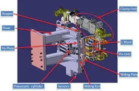
Slide unit is a positioning unit which is used to position the car panel, units, weld gun, and the robots for the certain operations in the BIW fixture. The slide units comprises of the sliding mechanism involved used in the fixture. It is used when there not much floor space available.
Slide unit is classification based on the type of guide ways used
- Hardened guide way.
- LM guide way
Slide unit classification based on the prime mover used
- Manual slides
- Hydraulic/pneumatic slides.
- CNC slides
Slide unit classification based on the orientation
- Horizontal slide unit
- Vertical slide unit
- Angular slide unit
Basic requirements of slide unit design
- Reverse stroke 10mm to be considered in both forward & retracted condition.
- Cylinder and LM guides should be validated for load and stroke conditions.
- Master guide way should be constrained and the subsidiary guide way to be free.
- Mechanical hard stop to be considered for both extended & retracted condition.
- Shock absorber should be used for both extended & retracted condition to reduce impact load.
- Slide to be locked/clamped in the working position.
- Slide to be locked with a safety pin in the retracted position during transportation to prevent damage.
- The two end limits to be sensed externally by a proximity switch.
- The design should be checked for screw accessibility, ease of assembly, machinability of parts.
- The LM guide & rails are integral assemblies and should not be separated at any cost.
- LM guide ways must be lubricated for long life
Conclusion
Thus the design methodolgy of BIW fixture was learned.