Week 11- Assembly Workbench
Aim
- To create the individual parts and then create a assembly of those parts in the assembly workbench in Catia V5.
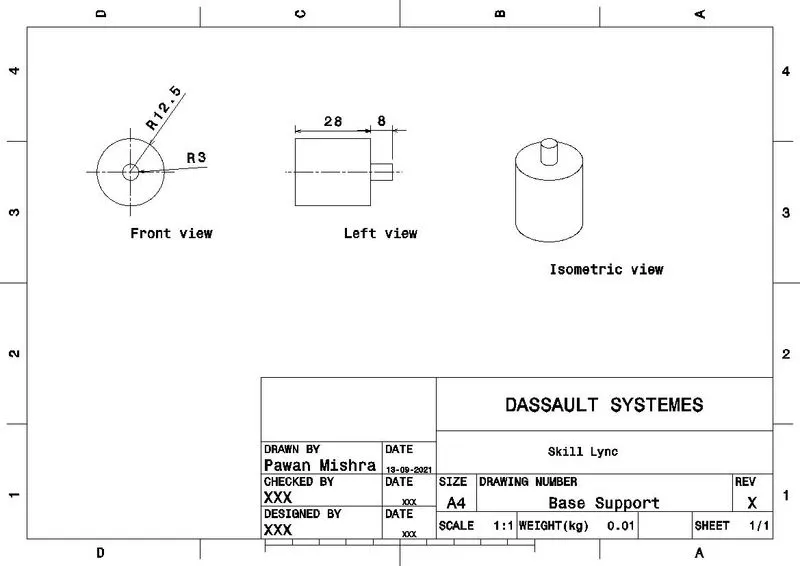
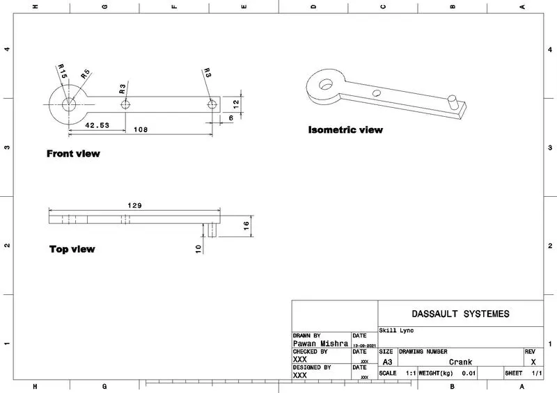
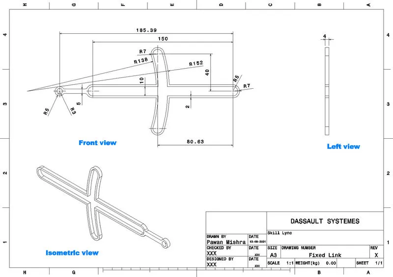
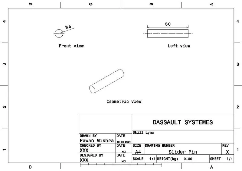
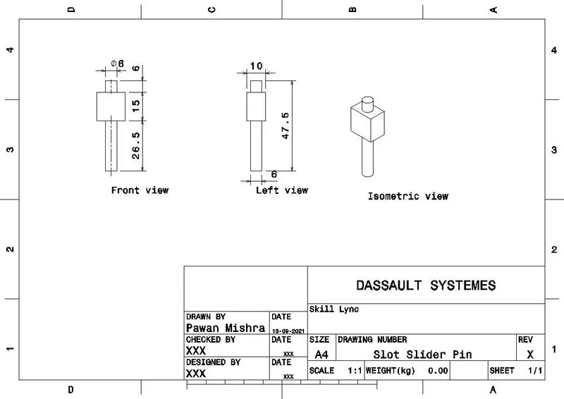
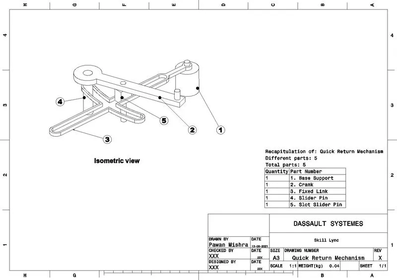
- To create an 2D drawing of the modelled parts.
Design Methodology
- The fully defined sketches of the parts were drawn withrespect to the input drawing.
- The sketches were converted into solid/3D parts using required commands.
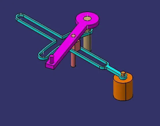
- Then the Parts were inserted into the assembly workbench and then the necessary constraints were provided to complete the assembly.
Quick Return Mechanism
Sketches and Part Images
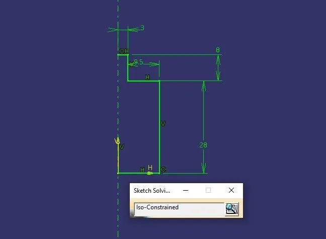
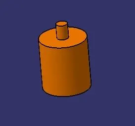
Base Support
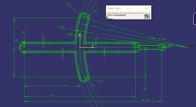
Link

Crank
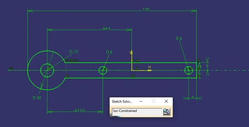
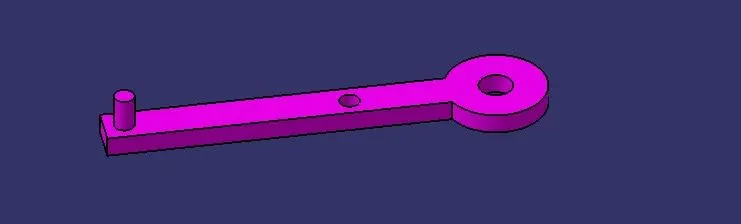
Slider Pin
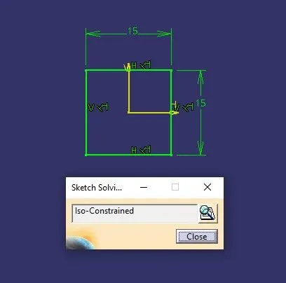
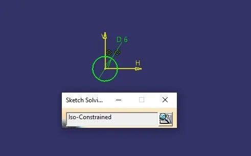
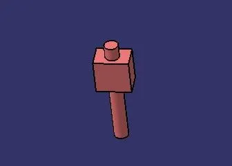
Pin
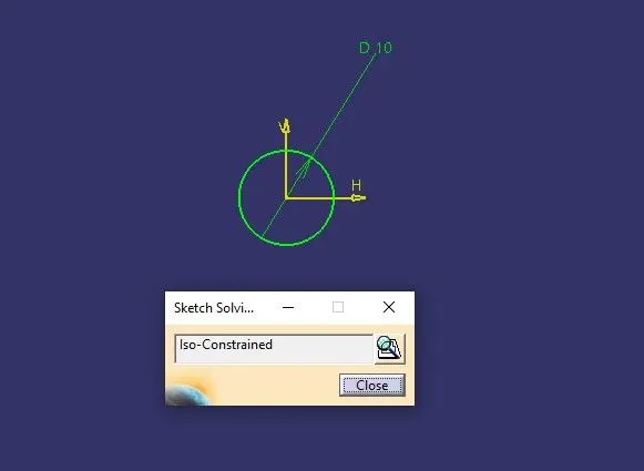
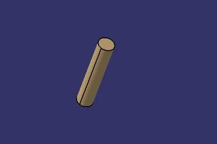
Constraints
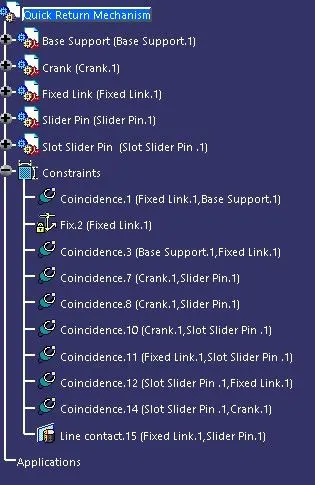
Assembly
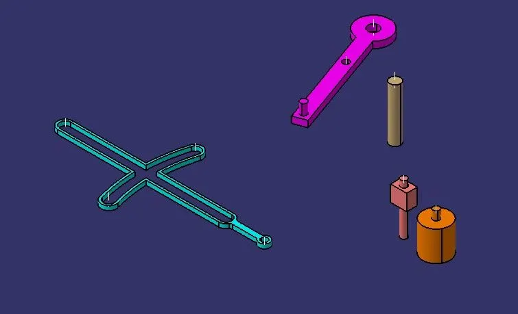
Exploded View
Part Drafting Images
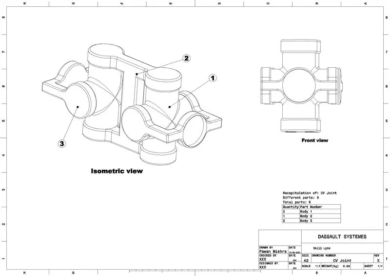
CV joint
Constant-velocity joints also known as homokinetic joints allow a drive shaft to transmit power through a variable angle, at constant rotational speed, without an appreciable increase in friction or play. They are mainly used in front wheel vehicles.
Part Images and sketches
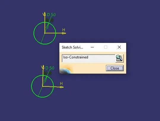
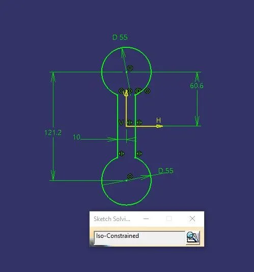
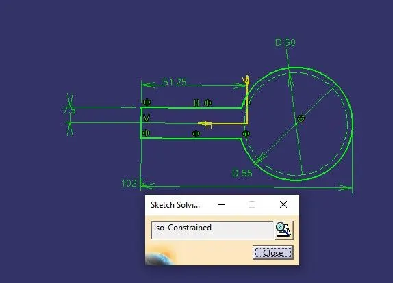
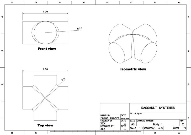
Body 1
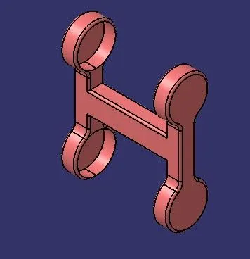
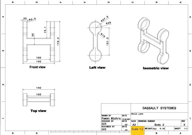
Body 2
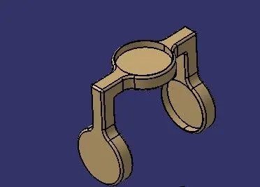
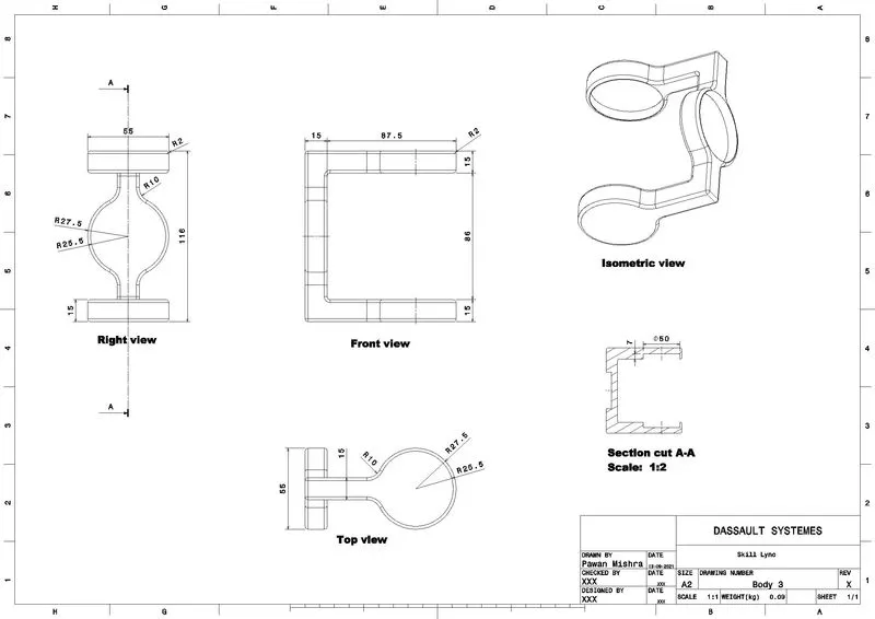
Body 3
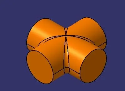
Constraints
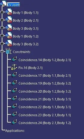
Assembly
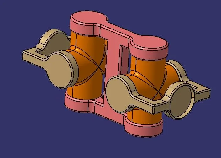
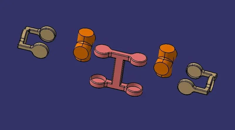
Exploded View
Drafting Images
Conclusion
Thus the Quick return mechanism and CV joint were modeled and assembled in catia V5 and the parts were drafted.