Week 9 - Attachment Feature Creation - Challenge 2
Aim
To Create the boss and Dog House for the Centre console coin holder considering the design rules.
Boss
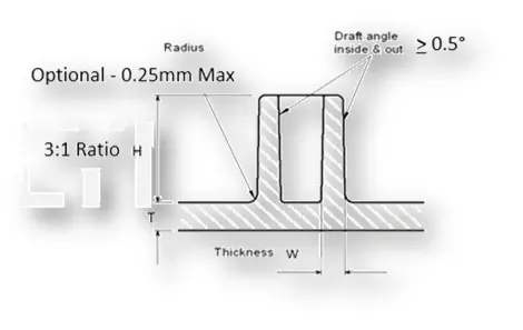
A boss is a protruding feature on a work piece.They are commonly found in injection molding designs to aid in the assembly of molded parts by providing a channel for a screw.
General Guidelines for Bosses
- Draft - 0.5 degrees on walls of boss
- Thickness - Typically 40%* of the nominal wall at the base.
- Height to Diameter Ratio - 3:1
- Radii - 0.25mm maximum radii
Dog house
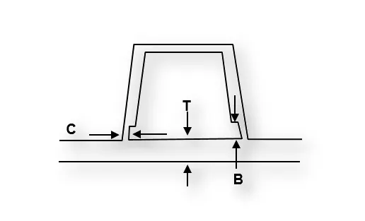
Dog house is an engineering feature used in plastic trim design. Dog houses are used as supporting feature. Doghouse is a embossment for screws to attach one piece of plastic to another one. For example, It can be used for adding garnish for the bumper cover.
Design Input
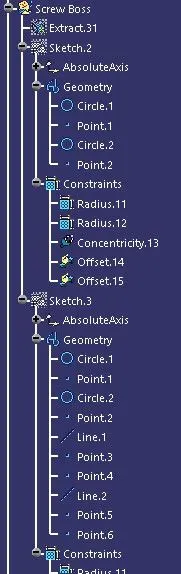
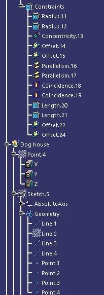
Tree structure
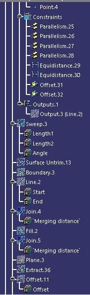
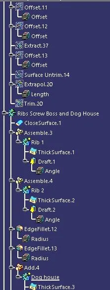
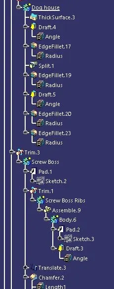
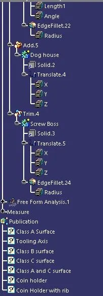
Tooling axis
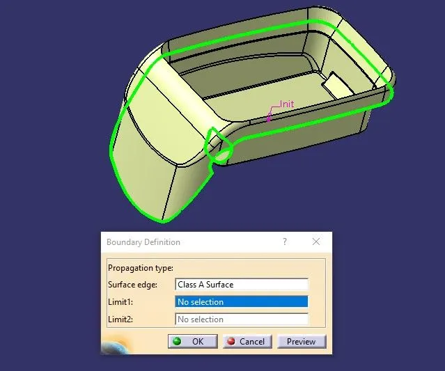
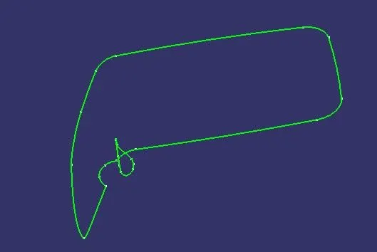
Check the class A surface
- The input class A surface is checked for any gaps or disjoints using the join or boundary commands.
- If there is any Minor error the it can be rectified or else send back to the Class A surface designer to make the necessary modifications properly.
In this case we can see that the Class A surface does not have any gaps or disjoints and has smooth and continuous boundary.
Create the Tooling axis
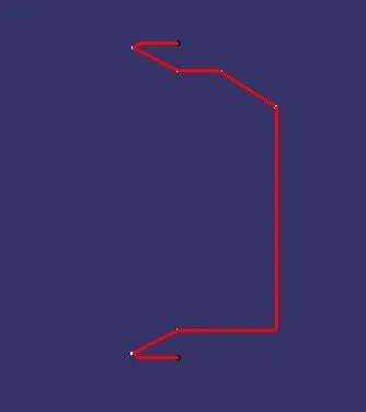
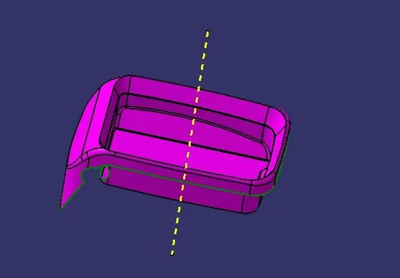
The tooling axis is the direction in which the core and cavity opens and closes. In this case we can see that the bin area surface can be used as tooling axis center point. The intersecting lines can be drawn to identify the surfaces which could not be cleared in tooling axis.
Side core axis
We can see that the dod house inner surfaces cannot be cleared with the above tooling direction hence we create a tooling axis satisfying the side core.
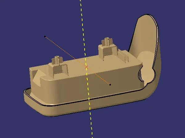
Bisecting line tooling axis
The bisecting line is used to create a line bisecting the two reference lines created in normal direction. The bisecting lines helps us to achieve the average draft angle between the two reference lines.
Publish
In the next step publish the tooling axis and Class A,B,C surfaces so that we can access it easily and use it for further creation of surfaces or thick body.
Draft Analysis
Once the tooling axis is created the draft analysis can be done. For viewing the draft analysis results we need to change the view parameters into customise mode enabling only the material.
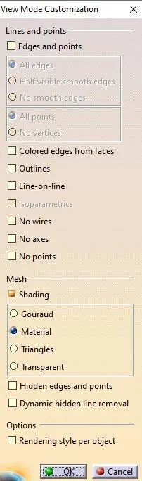
Go to insert-analysis-feature draft analysis.
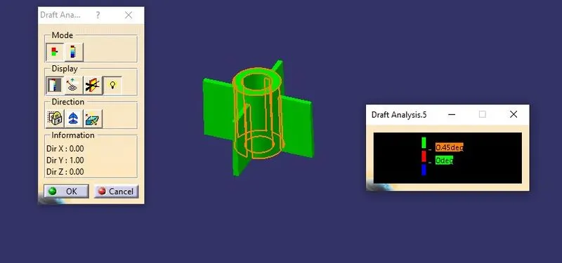
The compass option is used to choose the tooling axis. The color coding shows the result of the draft analysis done. The limits of the draft angle can be changes according to the needs.
Types of the modes in the analysis
A single limt can be chosen to show the positive or negative draft
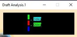
Multiple limits can also be set based on the requirements
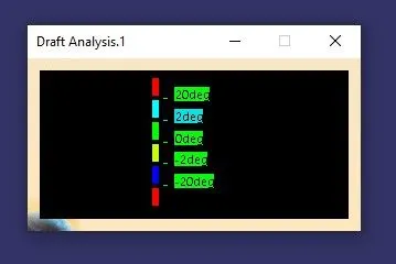
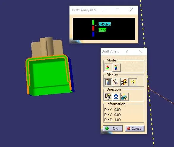
The draft angle value can be found at any given point of the surface. for the ribs 0.5 degree is optimum and we can see that the some parts of the model has positive draft angle highlighted in green color and some parts with zero draft highlighted in blue color. The negative draft is shown in red color.
We can see that the dog house inner faces clear the side core tooling axis and the screw boss clearing the main tooling axis
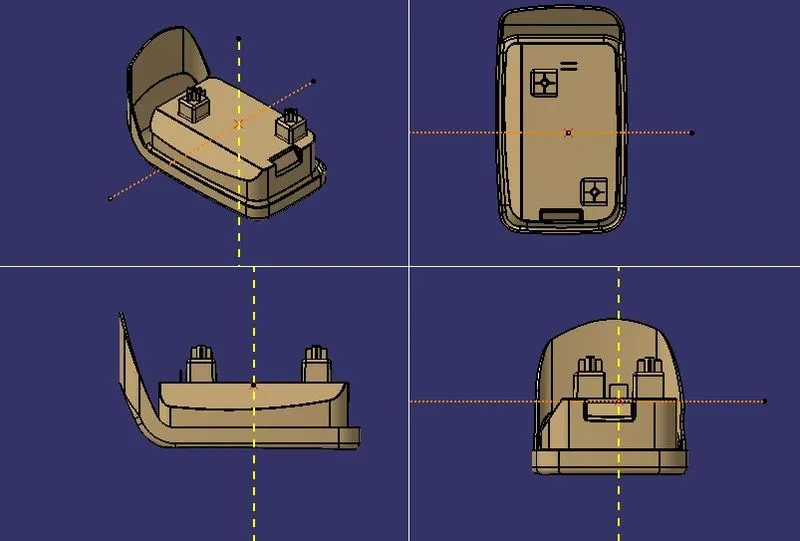
Part image
Conclusion
Thus the boss and Dog House are Created for the Centre console coin holder considering the design rules.