Week 2:- BiW Fixture Basics Challenge
BIW Fixture Design
Aim
To study the BIW fixture design basics.
1.Process of project execution activity
Project Execution
Project execution is carrying out the already designed plan. It involves putting into action all the activities that were set in the previous processes of the project cycle. All the activities are done according to the set plans, sequence and procedures to satisfy the requirements of the project. The purpose of implementing or executing a project is to deliver the expected results. Concerning the span of the project processes, this project execution is the longest and is the one that utilizes a lot of the resources.
The various activities used in the project execution of a BIW fixture design are shown with the help of the flowchart
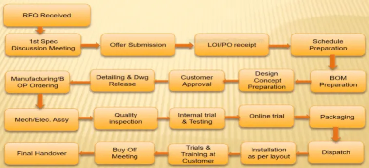
The process involved in process design
Step:1 Request for quote (RFQ)
RFQ is an excellent tool for efficient and cost-effective sourcing. It is available in many formats, generally company have their own format.RFQ is also known as an invitation for bid (IFB). It is a process in which a company asks selected suppliers and contractors to submit price quotes and bids for the chance to fulfill certain tasks or projects. It is a document that details a buyer’s requirements and asks vendors to respond with pricing and payment terms. It must contain details like technical data, cost, timeline of the project, etc. Based on the customer requirement the project execution plan and estimation are made.
Step2: Specification preparation
In the next step the detailed technical details, cost break down, project schedule, resources required to complete the project within the timeline are decided. The time and resources required to execute the individual tasks like part modeling, analysis, drafting and detailing, design for manufacture, applying GD&T to the components, purchase of parts etc, are considered and an outline is made.
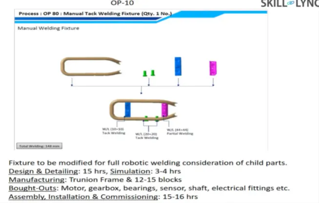
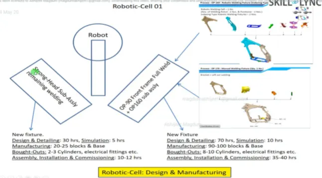
A detailed specification sheet for manual tack welding fixture for placing a technical offer.
Step3: Offer submission
All the relevant details from the previous step is sent to the customer. All the techical drawings, detailed cost breakdown, project timeline, CAD files are shared with the customer.
Step4: Letter Of intent (LOI) or Purchase order
After the offer is submitted Purchase order is sent by the customer if the offer details is satisfactory to the customers. The customer may compare the offer with other competitors and decide whether to place the order or not. Purchase order is a contract or confirmation of that the order for such a material is placed. The LOI is sent with final specifications and the terms and conditions.
Step5: Schedule Preparation
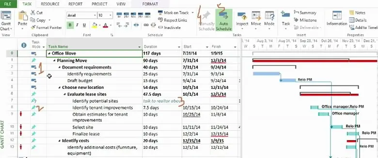
The required time for the individual tasks is calculated and the suitable resources are allocated. Since the processes are interdependent the completion of the tasks on time is essential to complete the project within the schedule. A back up plan is also made to accounnt for any unplanned delay in unfavorable circumstances. The final schedule is made and the whole team should strive to completion the tasks on time to complete the project within the estimated timeline. The schedule can be made and tracked using software like windchill, Primevera, Gant chart etc.
A scheduling sample
Step6: BOM preparation
A bill of materials (BOM) is a centralized source of information containing a list of items used to manufacture a product and the instructions on how to do so. The decision of make/buy is made and indicated in the BOM. It lists the consumables,vendor name, quantity of items, bought out parts etc, in a tabular form.
A sample BOM for a reactor
Step7: Design Conceptualization
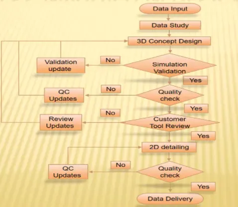
All the basic ideas from the previous stages is taken into consideration and the concept based on the customer specification is prepared in the form of 3d models, drawings, DFM, is made and sent to the customer for approval for the further processes.
Step8: Cutomer Approval
It is also known as the design approval process. The customer studies the design concept and approves it if all the specifications are met. If there are any changes to be made it is communicated. If any changes are stated by the customer the specific teams work on it and send the updated details. If the customer is satisfied then the project is moved to the next step.
Step9: Detailing and drawing release
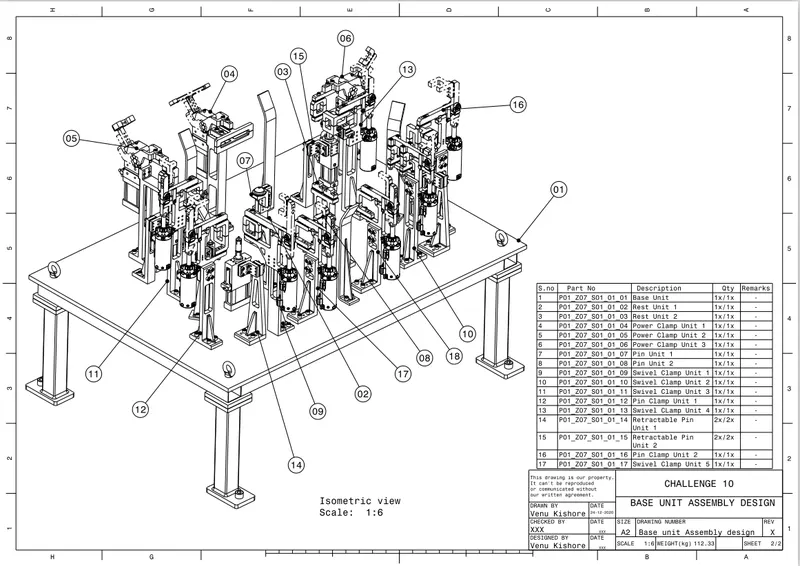
Once the customer gives the consent for manufacturing the final drawing for manufacturing is prepared. The separate list for parts to be manufactured and bought are prepared. The standard parts are chosen according to the requirement from the catalogue. The motor, mylar, shims can be outsourced. The surface finish, tolerance, material, welding parameters are mentioned in the drawing sheet. The drawings are verified and then sent for the production.
Step10: Mechanical and Electrical Assembly
Once the individual parts are manufactured and the quality check are done the assembly process starts. The mechanical(mylar, base unit, clamp unit, fasteners, locators etc) and electrical parts(switches, sensors, motors etc) are assembled as per the drawing sheet.The assembly stations are made for ease of assembly and time saving. once the parts are assembled the quality check is done again to check the compliance of the output to the mentioned specifications. If all the dimension are within the limits the part is sent for testing.
Step11: Internal trial and testing
Once the fixture is assembled then its functionality and reliability is tested. The parametrs clamping of the component, location of hole with the pin provided, loading and unloading of the panel is checked. The ergonomics of the fixture operation is also tested. If these criterias are matched then the weld gun travel path is checked. The the part is sent to the quality inspection team.If the trial and testing passes then the fixture is considered ready for manufacturing.
Step12: Online training
Once the internal trial is completed the online training commences. The entire process is carried out in manual and automated methods. The proper functioning of the sensors, alarms, actuator, valves, motor, are checked. The cycle time of the process is compared to the estimated cycle time. Once the BIW fixture clears the online training it is ready for production
Step13: Packaging
Packaging is enclosing or protecting products for distribution, storage, sale, and use. The tested fixture is disassembled and the individual parts are packaged to avoid any damage to the intricate parts. The part name, part number, quantity is labelled. The handling guidelines are also mentioned.
Step14: Dispatch
The packaged fixture with all its components is dispatched through ship, air, trucks, or container. Proper method should be chosen to ensure safey delivery.
Step15: Installation
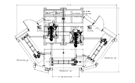
Once the package is delivered at the customers location, the installation of the fixture as per the specification is done. All the stations are installed as specified in the layout. The bases are assembled on a flat floor to avoid deviations. The shims can be used to make adjustments. The whole assembly is checked for functionality as intended.
Step16: Trial and training at customer end
After the fixture installation the production trial begins. At the same time the operators at the customer end are trained to operate the fixture. The loading, unloading, operation, safety systems, etc are taught to the operator. The entire operation from loading to unloading is clearly explained
Step17: Buy off meet
The customer feed back on the training and fixture is obtained, if the customer requires any additional features he has to pay the extra cost. If something is not according to the PO then the necessary corrections are made. The service and warranty,documents are signed.
Step18: Final handover
Once all the legal formalitities and paper work is completed then the fixture is handed over to the customer.
2. Types of joining process
Joining
Joining is a manufacturing processes by which two or more materials can be permanently or temporarily joined or assembled together with or without the application of external element in order to form a single unit. Joining examples are welding, brazing, soldering, adhesive bonding of materials.
• Joining produces permanent joint between the parts to be assembled.
• Joined parts cannot be separated easily by application of forces.
• Joining is mainly used to assemble many parts to make a system.
Riveting
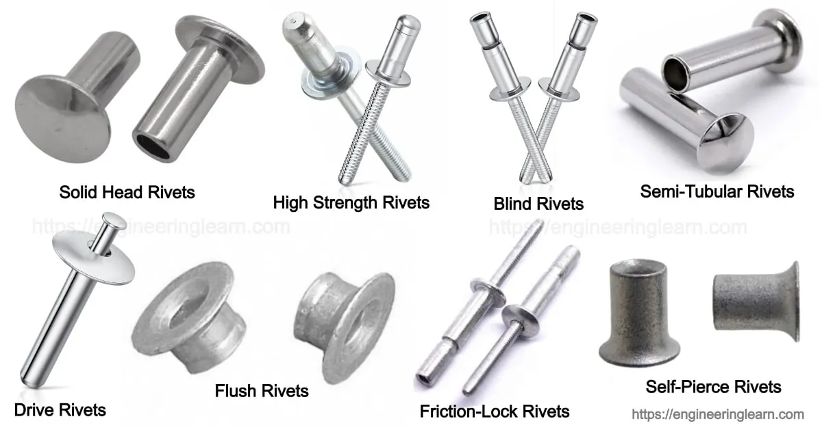
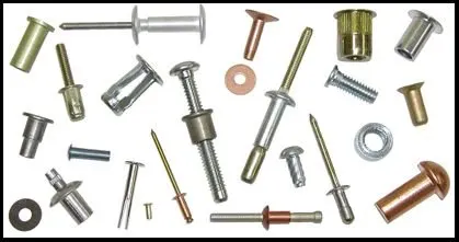
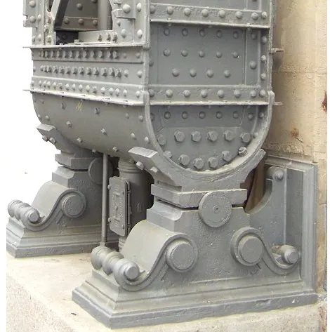
A rivet is a mechanical fastener with a plane unthreaded shaft that is inserted through holes to join two or more parts together. A permanently formed head at each end prevents the rivet from removal from the hole. The shaft prevents any radial movements of the components. it is used for thin metal plates.
A riveted girder
Advantages
- Cost effective
- Flexibility in design
- Durability
- Easy inspection and maintenance
Disadvantages
- Increase in structural weight
- No good appearance
- More workforce is required.
Welding
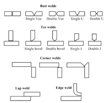
Welding is a joining process in which two or more parts are joined or coalesced at their contacting surfaces with application of heat with or without application of pressure.
Weld joints
Advantages
- Welded joint is strong and permanent.
- Welding provides smooth appearance and has simplicity in design.
- It can be done in any shape and any direction.
- Welding process can be automated.
Disadvantages
- High labor cost
- Members may become distorted due to uneven heating and cooling during welding.
- To dismantle a welded joint we have to break the weld.
- High initial investment
Fastening
A fastener is a device that mechanically joins two or more objects together. The fasteners can be used to make permanent or non-permanent joints. This allows the joints to be dismantled or removed without damaging the joined parts. Metal fasteners must be strong and be able to bear significant loads. They are often manufactured using powder metallurgical and casting processes.
Threaded fasteners are the most widely and commonly used for assembling parts because they offer ease in installing and uninstalling as required. Fastener threads are standardized to two major standards: ISO (Metric) and ANSI (Unified). Their threads can also be right-handed or left-handed depending on the application.
Advantages
- Weight reduction in the component is typically achieved.
- Ability to join high-strength steel up to a tensile strength of Rm = 1500 MPa.
- Minimum space requirements are needed within the tool.
- Tool maintenance is easy and simple.
Disadvantages
- They carry all load at specific points, which contribute to fatigue.
- Difficulty of refastening
- Corrosion
Brazing
Brazing is a metal-joining process in which two or more metal parts are joined together by melting and flowing a filler metal into the joint, the filler metal has a lower melting point than the adjoining metal. Brazing differs from welding since it does not melt the work pieces join them.
It can be used to join wide array of materials, like brass, copper, stainless steel, aluminum, zinc-coated steel, and ceramics. Laser brazing can be used to join dissimilar metals.it can be used to join almost all metals except aluminium and magnesium.
Advantages
- Corrosion resistant joints.
- Brazing preserves metallurgical characteristics of material because low temperatures.
- Provide excellent sealing as compared to spot welding, riveting or fastening.
- It is easy to automate for bulk production.
Disadvantages
- The job size is limited
- The color of the joint is often different from that of the base metal that create an aesthetic disadvantage.
- Weak joint as compared to welding.
- Metal to join must very close to ensure capillary action of molten filler metal.
Soldering
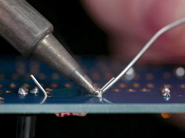
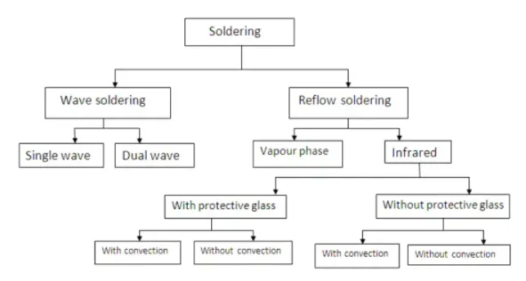
Soldering is a joining process used to join different types of metals together by melting solder. Solder is a metal alloy usually made of tin and lead which is melted using a hot iron. The iron is heated to temperatures above 600 degrees fahrenheit which then cools to create a strong electrical bond. The filler is made up of antimony, bismuth, brass, copper, indium, tin or silver. the flux helps prevent oxidation and can sometimes chemically clean the metal and commonly the rosin flux is used which helps to improve the mechanical strength and electrical contact of electrical joints.
Types
- Soft soldering (90 °C - 450 °C)
- Hard (silver) soldering (>450 °C)
Advantages
- It can be operated at low temperature.
- Base metal does not melt.
- Both metals and non-metals can be joined by this process.
- Less time required to join.
Disadvantages
- Strength of joint is less.
- This is not useful when joint works under high temperature.
- It is not useful at Long length weldings.
- Heavy metals cannot be welded by this operation.
Hemming and seaming
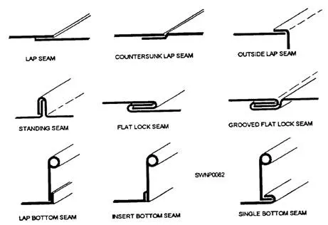
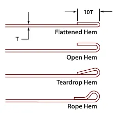
Hemming and seaming are two similar metalworking processes in which a sheet metal edge is rolled over onto itself. Hemming is the process in which the edge is rolled flush to itself, while a seam joins the edges of two materials. The hemming operation is used to connect parts together, to improve the appearance of a part and to reinforce part edges.
Advantages
- using robotic hemming high volume production can be met.
- Low cost and simple in operation.
Disadvantages
- Material deformation may occur.
- Dimensional variation may occur.
Adhesive Bonding
Adhesive bonding uses an adhesive material, or glue, to join a wide range of dissimilar materials. The glue does not generally react with the materials being bonded. The Surfaces to be bonded are cleaned if necessary. Then the two-part adhesives are accurately mixed and blended together. Then the adhesives are placed at the joint in position using a dispenser. If the location is complex and needs to be accurate then jigging is necessary along with the application of a clamping force. Sometimes the heating of adhesive in an oven for a certain curing time is required to form a secure bond. The common adhesive materials are elastomers, polymers, super glue like cyanoacrylates, acyrylic resin, epoxies, polyurethanes, methylmethacrylates, rubber-based anti-flutters, PVC, butyls, bitumens, thermoplastics.
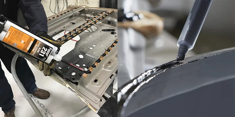
Applications
- Production of aluminium closures and all-aluminium car body structures
- sound dampening
- structural bonding
Advantages
- It can be used to make superior stress-bearing components.
- Adhesives distribute stress load evenly over a broad area which reduces stress on the joint.
- Adhesive bonding can provide smooth surface appearance.
- Irregular shapes and dissimialar materials at low temperature can also be joined.
Disadvantages
- It mostly requires surface preparation treatments, impurities impair the bonding strength.
- More time is required.
-
Difficult disassembly of joined parts
- Low creep strength.
3. Resistance welding and its application in automotive industry
Resistance Welding
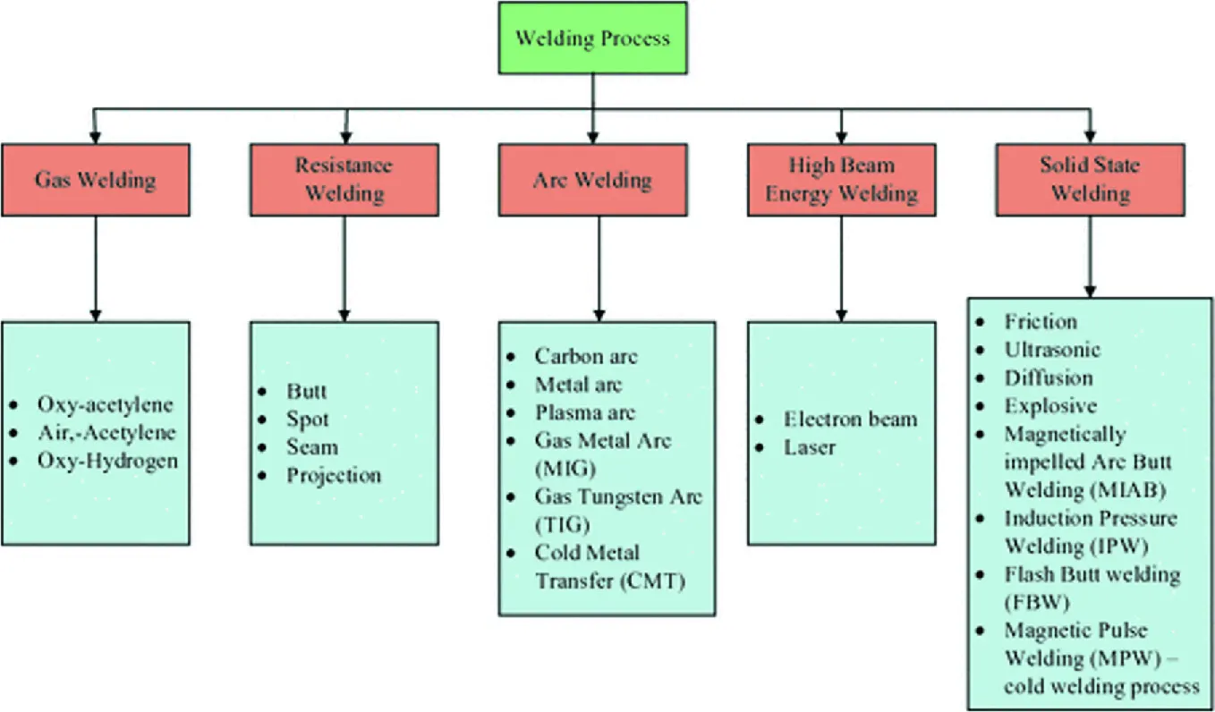
Resistance welding is the joining of metals by the application of current and force through the welded parts develops resistance and thus creates a nugget in the melt joint. It can be used for automotive, aerospace and industrial applications. Resistance welding is a fusion welding process that requires the application of both heat and pressure to achieve a proper joint.
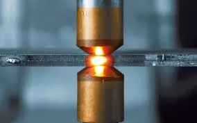
- Resistance welding is widely used in automotive industries.
- Projection welding is widely used in production of nut and bolt.
- Seam welding is used to produce leak prove joint required in small tanks, boilers etc.
- Flash welding is used to welding pipes and tubes.
Resistance seam welding
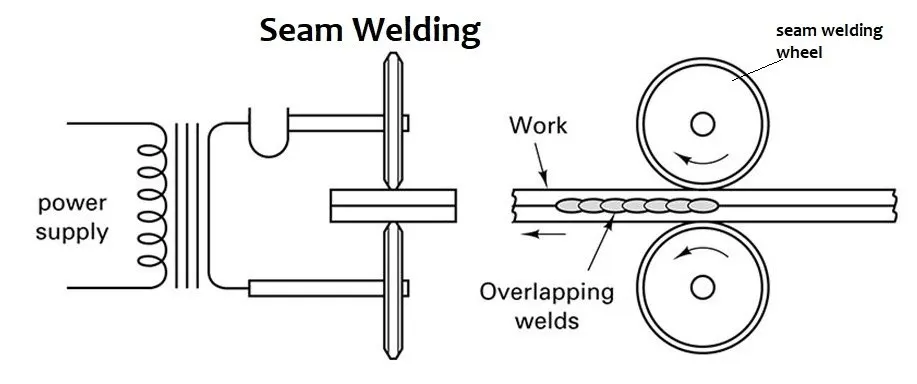
Resistance seam welding is a a continuous weld is produced by passing the work between rotating wheel-shaped electrodes, which exert the welding pressure and also conduct the welding current. It may be continuous or intermittent. It is used to make airtight joints.
In this process the rollers are contacted to the workpiece. The high current is passed through these rollers. Due to increase in temperature the interface surfaces will melt and form a weld joint. Now the rollers start rolling on the work plates. This will form a continuous weld joint.
The movement time of the weld and electrode is controlled to assure that the weld overlaps and the workpiece is not too hot.
Applications
- Fuel tank assembly
- welding pipes and tubes
Advantages
- It can produce airtight welds
- It is a fast welding process
- No flux or filler is required
Disadvantages
- Only straight or uniformly curved line welds are possible.
- Limited thickness of sheet can only be used.(Upto 3mm)
Resistance projection welding
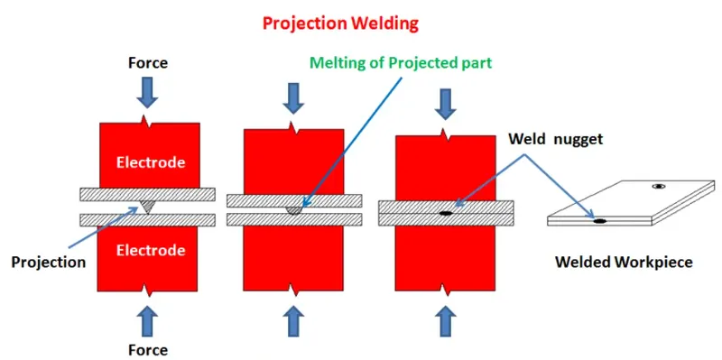
Projection welding is quite similar to as spot welding in operation. But in projection welding a dimple is produced on work pieces at the location where weld is desired.The work pieces are held between electrode and a large amount of current pass through it. A small amount of pressure is applied through electrode on welding plates. The current pass through dimple which melt down it and the pressure causes the dimple flatten and form a weld.
Advantages
- It has no limitation on the thickness of the metals to be welded.
- More than one spot can be made in single operation.
- This process is suitable for automation.
- It gives a good heat balance while welding.
Disadvantages
- It can not be applied to some type of brasses and coppers.
- Projections cannot be made in thin workpieces.
- Equipments are costlier.
Resistance spot welding
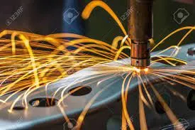
In this process, the parts to be joined are held firmly between two heavy electrodes, which are connected in the secondary circuit of the step-down transformers. The maximum resistance exists at the contact surface of the two parts being joined and high heat is developed.The spot size mainly depends on electrode size (4-7 mm).
Advantages
- Spot welding is quick and easy.
- No fluxes or filler metal is required to create a joints by spot welding
- Automation is feasible to reduce cycle time.
- Thin sheets can be easily spot welded.
Disadvantages
- It can create only localized joints.
- Cleanliness of the plates is very important to produce defect free joint.
Resistance Butt welding
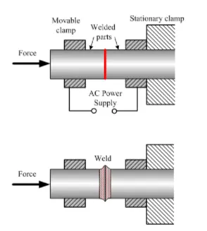
The heat is produced by the electric resistance at the butting surface by the flow of current and no arcing takes place between the surfaces being joined. A light pressure and a heavy current passed through the joint.When sufficient heat has been produced the two parts are suddenly pressed together and the current is simultaneously stopped. A thin film is produced around the joint which is subsequently removed to give a weld of this type.
Application
It is used for welding chains, rail ends, shaft axles etc.
Advantages
- It is a cheaper process
- It offers great strength factor.
Disadvantages
- It has More chances of fire hazards.
- Metal is lost during flashing and upsetting.
- Concentricity and straightness of the work pieces during welding process is often difficult to maintain.
4. Fusion welding and its application in automotive industry
Fusion welding is a process that uses heat to join or fuse two or more materials by heating them to melting point. The process may or may not require the use a filler material. External application of pressure is not required for fusion welding processes, except for resistance welding, where substantial contact pressure is required during welding for sound joining.
Arc Welding
Shielded metal arc welding(SMAW)
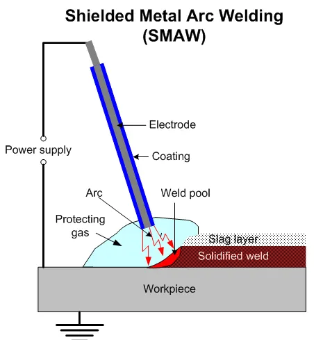
Shielded Metal Arc Welding (SMAW), also known as manual metal arc welding (MMA or MMAW), flux shielded arc welding or stick welding. It Suitable for welding both ferrous and non-ferrous materials in all positions. It uses a metallic consumable electrode of a proper composition for generating arc between itself and the parent work piece. The molten electrode metal fills the weld gap and joins the work pieces. The electrodes are coated with a shielding flux of a suitable composition. The flux melts together with the electrode metallic core, forming a gas and a slag, shielding the arc and the weld pool. The flux cleans the metal surface, supplies some alloying elements to the weld, protects the molten metal from oxidation and stabilizes the arc. The slag is removed after solidification.
The SMAW welding machine provides constant current (CC) using direct current (DC) or alternating current (AC). Direct current operates on different directions based on the polarity. Alternating current switches between directions.
Applications
- Construction
- Pipelines
- Shipbuilding
- Underwater welding
- Farm machinery manufacturing
Advantages
-
Simple, portable and inexpensive equipment.
-
Wide variety of metals, welding positions and electrodes are applicable.
-
Suitable for outdoor applications.
Disadvantages
-
The process is discontinuous due to limited length of the electrodes.
-
Weld may contain slag which requires cleaning.
-
Fumes may make the process control difficult.
Metal Inert gas(MIG) welding
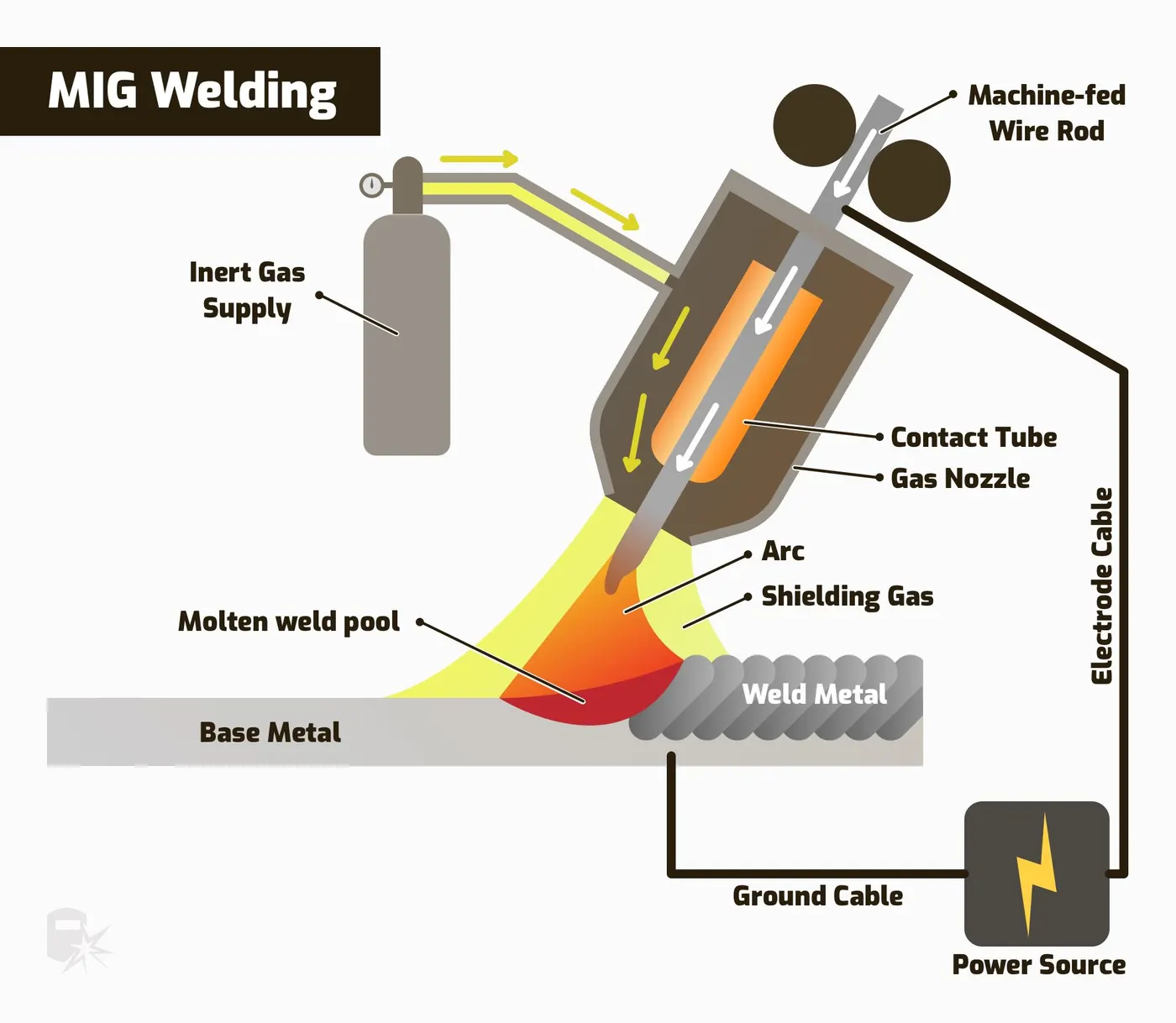
MIG welding is also known as Gas Metal Arc Welding (GMAW). MIG welding uses an electric arc between a consumable wire electrode and the workpiece leading them to melt and join. The shielding gas is used to protect the weld from airborne contaminants, or oxidation. It is easier to learn MIG welding and it produces welds that require little to no cleaning and finishing.
Applications
- MIG welding is most commonly used to repair cars, motorbikes, recreational vehicles etc.
- MIG welding is best suited for fabrication of sheet metal.
Advantages
- It can be used to weld thicker materials
- It has Greater deposition rates.
- It has shorter lead times
- The Production cost is low
Disadvantages
- Higher initial setup cost
- Less efficient where high duty cycle requirements are necessary
- Radiation effects are more severe
Tunsten Inert Gas welding(TIG)
It is also known as Gas Tungsten Arc Welding (GTAW). This arc process uses a non-consumable tungsten electrode to create the arc between the electrode and the base plate. An inert shielding gas is used to protect from oxidation or other atmospheric contamination. This process can be used on thin parts, and requires the consumable wire for filling the gap. The TIG welders require highly specialized training to ensure they achieve proper precision and accuracy.
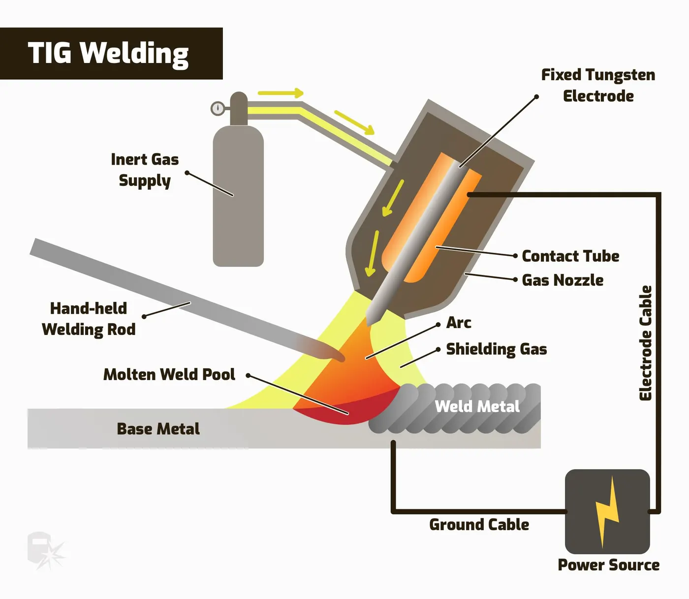
Applications
- In Aerospace industry to fuse the intricate airplane parts and the plane’s skin while still enhancing its much valued aesthetic value.
- Automobile Industry to produce corrosion resistant metal fusion.
- Industries use TIG welding on the thin workpieces, and also for nonferrous metals.
Advantages
- Tig welding is used to make rust-resistant metal fusion.
- High precision and strength weld can be made.
- TIG welding does not produce slag
- It can be performed in any welding position
Disadvantages
- It is a slow welding process
- High skilled labor is needed for TIG welding.
- Operation cost is much expensive
- Welders are exposed to high intensities of light.
Plasma Arc welding
Plasma arc welding is a liquid state welding process in which, the metal to metal joint forms in molten state. The hot ionized gases are known as Plasma. These hot ionized gases used to heating the work plates, and the joint is created due to fusion. This welding process is same as TIG welding process except plasma is used to weld the work pieces instead of arc. Filler material may or may not be used. The flux also prevents spatter and sparks while suppressing ultraviolet radiation and fumes.
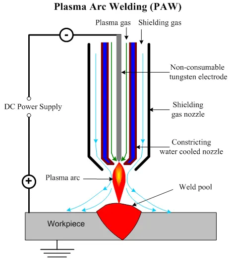
Applications
- This welding is used in marine and aerospace industries.
- It is used to weld pipes and tubes of stainless steel or titanium.
- It is mostly used in electronic industries.
- It is used to repair tools, die and mold.
Advantages
- High welding speed can be achieved
- It can be easily used to weld hard and thick work pieces.
- The distance between tool and work piece does not effects the arc formation.
- Low power consumption for same size weld.
- More stable arc produced by PAW method.
Disadvantages
- Higher equipment cost.
- Noisy operation.
- More radiation
- High maintenance cost.
Submerged arc welding
It is a joining process that involves the formation of an electric arc between a continuously fed electrode and the workpiece to be welded. A blanket of powdered flux surrounds and covers the arc and, when molten, provides electrical conduction between the metal to be joined and the electrode. The SAW process is usually automated.Material applications of SAW include carbon steels, low alloy steels, stainless steels, nickel-based alloys,etc
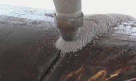
Applications
- It can be employed to weld carbon, steel, aluminum, titanium, and minimal alloy materials.
- Used in the industries of welding pipes, structural manufacturing, vessel manufacturing, storage tanks, and ship buildings
Advantages
- At least half or more of the flux is recoverable
- Minimal welding fume is emitted
- Minimal arc light is emitted
- SAW is suitable for both indoor and outdoor works
- Less distortion
- Deep weld penetration
Disadvantages
- It can be performed only in the flat position.
- It cannot be used for complex shapes and is normally limited to long, straight seams or rotated vessels or pipes.
5. 3-2-1 principle
3-2-1 Principle
The 3-2-1 principle is the basic principle used in BIW fixture design. It is used to lock all six degree of freedom of the workpiece. It is a Component holding principle where three pins are located on any of the 1st principle plane(XY, YZ, ZX). And two pins are located on the 2nd plane which is perpendicular to the 1st plane, and at last one pin on the plane which is mutually perpendicular to the 1st and 2nd planes.By using this method Componet movement can be arrested in all six degrees of freedom.
The Location of a part to be machined involves mainly three steps: Supporting, Positioning, and Clamping. Every free body has a total of twelve degrees of freedom 6 translational degrees of freedom and and 6 rotational degrees of freedom(+X, -X, +Y, -Y, +Z, -Z). All the 12 degrees of freedom except the three transitional degrees of freedom (-X, -Y and -Z) must be fixed in order to locate the work piece in the fixture.
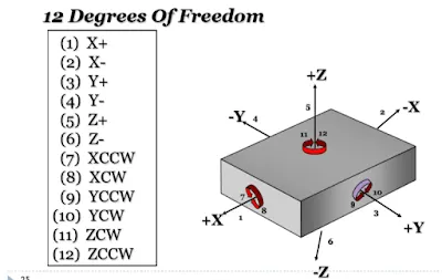
Locators used in 3-2-1 principle
Primary Locators
It arrests 5 DOF. Three primary locators are placed under the work-piece, it it also known as datum.
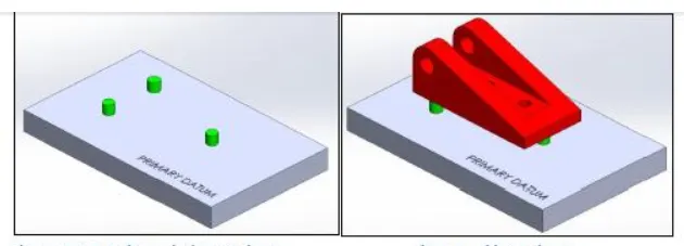
It stops Axial Movement downward along Z- axis and Rotation about the X and Y axis in both directions.
Secondary Locators
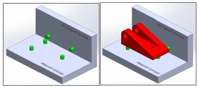
Tertiary Locators
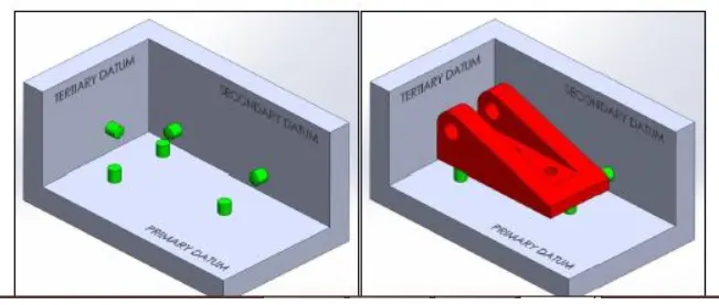
6. Body co-ordinate system(BCS)
Body Coordinate system in BIW
A coordinate system is a reference system consisting of a set of points, lines and surfaces.
used to detine the positions of points in space in either two or three dimensions. The body coordinate system has been widely used in the automotive industry for drawing of body parts, product and process design. In general BCS is also called as car line and Body line.
The body coordinate system helps to locate the parts in the assembly, design of fixture for the components and assembly of the components. Every car manufacturer may have different and unique BCS. It is a origin point from where all other measurements are made. It could be located anywhere in the vehicle. it assists in quality checks and enables the designers to create a standardized system.
Car body alignment is when the coordinate system relates back to the single coordinate system used in the overall car assembly. For a car it can be located at centre of the front wheels.
A vehicle’s (motion) degrees of freedom named in 3 main geometrical planes, such as transversal plane and symmetry plane. For ground vehicles, the motion in ground plane is often treated as the primary motion, which is why longitudinal, lateral and yaw are called in-ground-plane degrees of freedom. The remaining degrees of freedom are referred to as out-of-ground-plane.
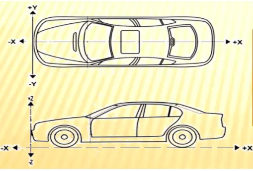
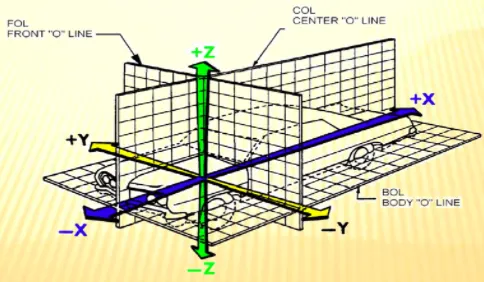
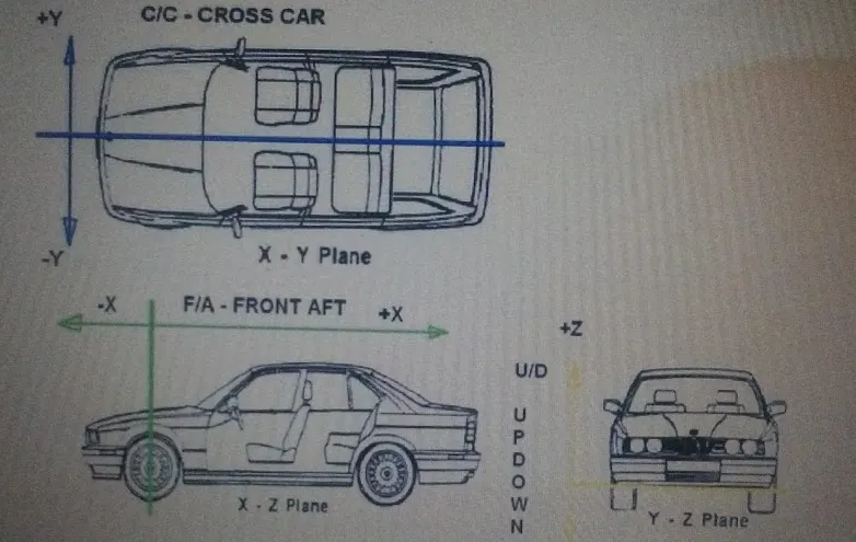
The directions meaning used in the BCS in the below image
- X=Longitudinal direction [(Fore & After - FIA) or (Front O Line - FOL)]
- Y=Transverse direction [(Cross car - C/C) or (center O line - COL)]
- Z=Vertical direction [(Up & Down - U/D) or (Bottom Line - BOL)]
- (OX) is defined at the front center of a vehicle,at the origin of the body coordinate system indicating the length of car
- (OZ) is located below the underbody of the car and it indicates height of car,
- The coordinate system (OY) is starting point for the center of the car body it indicates width of car.
7. Body plane system and its Significance
Body plane
Body planes are the reference planes in an automotive car. These planes are 3 mutually perpendicular imaginary planes. These are generally considered tobe present at the Driver position or sometimes at the engine location or at the front end of the car, depending on the customer. The Measurements from the body planes to the parts are called as bodyline dimension.
These body planes in car named as
- FOL - Front "O" Line
- COL - Centre "O" Line
- BOL - Body "O" Line
- The Measurement along FOL or X axis is called as F/A Front Aft
- The Measurement along COL or Y axis is called as C/C Cross Car
- The Measurement along BOL or Z axis is called as U/DUP Down
Significance
- These planes are used to define the GD&T of all car parts in a automotive domain.
- It helps in flawless design for assembly(DFA)
- It shows the location of any part in the assembly with respect to the origin.
Conclusion
Thus the basics of the BIW design was studied.