Radar Mast & Final Assembly of Yacht
Modeling of Sun seeker Predator Yacht
Introduction
This project is the second part of ultimate solid works course in skill lync, Solid works is used for planning, visual ideation, modeling, feasibility assessment, prototyping, and project management. In this module I have learnt how to make 2d sketches of the parts of a Sun seeker Predator yacht and convert them into surfaces and solid models using various tools. After creating individual parts they were assembled using the appropriate mates. Finally a photorealistic render was created using solid works visualize and photo view 360.
Sun seeker Predator Yacht
Sun seeker International is a British luxury performance motor yacht brand. Originally named Poole Power Boats, the company was founded by brothers Robert and John Braithwaite in 1969. The Sun seeker Predator yacht has all the hallmarks of greatness. like Striking style, remarkable power and an innovative use of light and space.
Objective
- To create fully defined sketches and model parts of Sun seeker predator Yacht in solidworks and learn surface modeling in better way.
- To create assembly of Sun seeker predator Yacht.
- To learn how to apply appearances and decals to various parts.
- To understand the application of lights, camera, in rendering.
- To create and photorealistic render of the Sun seeker predator Yacht using photo view 360 and solid works visualize.
Design methodology
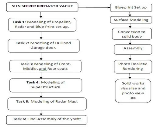
COMMANDS AND TOOLS USED
Extruded Surface
This tool is used to extrude a sketch or sketch contours in one or two directions to create a surface and its extent can be defined.
Swept surface.
This tool is used is used to sweep a closed profile along an open or closed path to create a surface. To create different shapes guide curves, profile orientations, twist angles may be used.
Lofted Surface
This tool is used to loft a surface between two or more profiles or sketches, by defining the start and end constraints and guide curves to control the shape.
Boundary Surface
This tool is used to create surface between profiles that are tangent or have continuous curvature in all directions.
Filled Surface
This tool is used to patch/fill a surface within a boundary which is defined by edges, sketches, or curves.
Ruled Surface
This tool is used to insert ruled surfaces in specified directions (tangent, normal, tapered, etc). from edges. After creating surface we can trim and knit the surfaces and also remove the connecting surfaces.
Offset Surface
This tool is used to offset surface using one or more contiguous faces. This tool creates a surface with gaps which can be repaired manually, or adjust the offset distance value and run the tool again.
Delete Face
This tool is used to delete faces from solid bodies to create surfaces, or delete a face from the surface body. It can also be used delete and patch faces to form continuous surface, or delete and fill to replace faces with a single face.
Extend surface
This tool is used to extend one or more edges or faces on a surface based on end condition and extension types.
Trim Surface
This tool is used to trim a surface where it intersects with another surface, a plane, or a sketch. It is defined by trim type( standard/mutual), trim tool (sketch, surface, plane), and selecting the surfaces to remove or keep.
Knit Surfaces
This tool is used to combine two or more adjacent, non intersecting surfaces into a single surface body provided they join at a edge. If the resulting knit surfaces encloses a volume, you can create a solid body.
Split Line
This tool is used to project an sketch, spline or surface face onto other surfaces or planar faces to split them into multiple bodies.
Thicken
Creates a solid feature by thickening one or more adjacent surfaces, multiple adjacent features can also be thickened if they are knitted.
Sketch
Sketch is 2D representation of 3d models and it is created using sketch entities like line, circle, arcs, spline, polygons,etc
Offset entities
Offset one or more sketch entities by a specified distance. If the original entity changes then the offset entity also changes when you rebuild the model.
Boss Extrude
Extrudes a sketch or selected sketch contours in one or two directions to create a solid feature. Extrude can also be offset to specified distance.
Fillet
Creates a rounded internal or external face along one or more edges on a solid or surface feature. Fillets can be of constant or variable size.
Edit Appearances
Edit the appearance of the entities in the model using appearance properties such as texture mapping and colors.
Lofted Boss
This feature adds material between two or more profiles to create a solid feature. It helps to generate complex geometries
Dome
This feature can be used on planar or non-planar surfaces to get a closed curved surface.
Extruded cut
This feature is used to remove materials from a solid model by extruding a sketched profile in or two directions. In multi body parts we can choose body to cut and bodies to keep.
Split
This tool is used to project an entity onto other curved or planar surfaces. We can create multiple bodies from single body.
Revolved Boss
Revolves a sketch or selected contours around a axis to create a solid feature. We can define axis of revolution and direction.
Trim Entities
Trims or extends a sketch entity to be coincident to another or deletes a sketch entity
Shell
Shell feature hollows the part and leaves the face open which you select and creating thin walled features on the remaining surfaces. If a face is not selected then a closed hollow model is created
Mirror
Mirrors features, faces, and bodies about a plane or a planar face. In assemblies you can mirror assembly features
Combine
Using the combine tool we can add, subtract, or find common area of two different bodies. A multi body part is required for this feature. In this model two different boss extrudes common area was chosen
Linear pattern
This feature patterns features, faces, and bodies in one or two linear directions. This can be defined by selecting reference geometry and instances can be skipped.
Chamfer
This feature is used to create sloped or angled corner or edge. It can be defined by either choosing distance distance or angle distance option.
Projected curves
This feature is used to create 3D curve from 2D curves from two different curves
Swept Boss
This feature sweeps a closed profile along an open or closed path to create a closed surface. A wide variety of shapes can be created by using the options like guide curves, twist and profile orientation options.
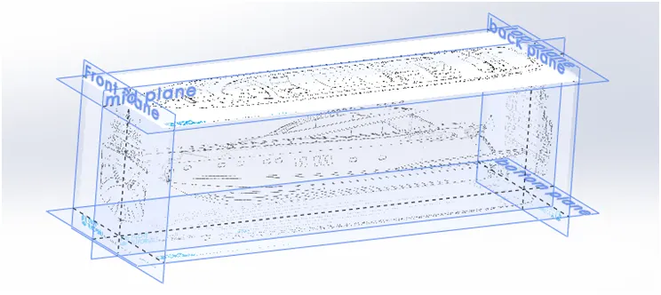
Blueprint set up
Under the Solid Works menu, go to Tools > Sketch Tools > Sketch Picture… and import
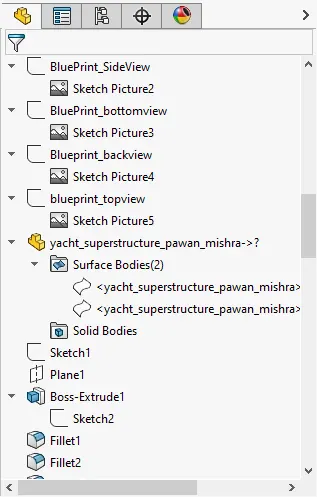
The blue print set up is actually setting up Sketch pictures in different planes to have reference for drawing the exact shape and giving proper dimensions to the model to get the intended design. Normally, the sketch pictures have orthographic projections. It helps the designer to model the parts with proper proportions and accurate dimensions. As the blueprint is used as a reference for modeling it must a accurate as possible to get the best results.
.
Propeller
The propeller is used to provide a method of propulsion so the yacht is able to move forward through the water. The propeller consists of two or more blades connected together by a central hub that attaches the blades to the engine shaft.
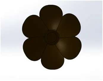
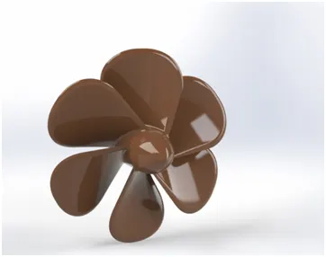
Features used to model the propeller
- Sketch
- Revolve
- Reference Geometry (plane)
- Lofted Boss
- Fillet
- Extruded Cut
- Circular Pattern
Radar
Radar stands for Radio Detection and Ranging. It is an Electromagnetic sensor used for detecting, locating, tracking, and recognizing objects of various kinds at considerable distances. It operates by transmitting electromagnetic energy toward objects, commonly referred to as targets, and observing the echoes returned from them.
The targets may be aircraft, ships, space craft , automotive vehicles, and astronomical bodies, or even birds, insects, and rain. Besides determining the presence, location, and velocity of such objects, radar can sometimes obtain their size and shape as well. The radar consists of antenna which transmits electromagnetic signals and the receiver receives those signals and gives precise results even in adverse weather.
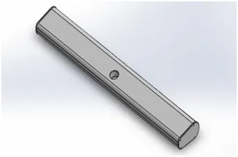
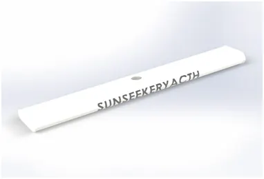
Features used to create radar
- Sketch
- Extruded Boss
- Fillet
- Extruded Cut
- Sketch pattern
- Split line
- Mirror
Hull
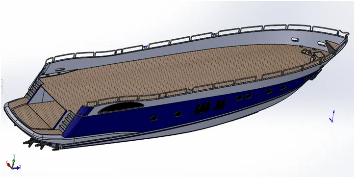
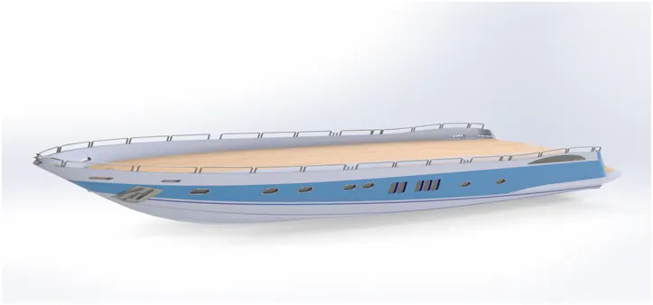
The hull of a ship is the most notable structural entity of the ship. To define the hull, it can be said that it is the watertight enclosure of the ship, which protects the cargo, machinery, and accommodation spaces of the ship from the weather, flooding, and structural damage. The hull is the portion of your boat that rides both in and on top of the water. It consists of parts like the railings, anchor, deck, windows, bow, and garage.
It is generally made up of steel, Aluminum, or wood. The different types of hull are displacement hull, flat bottom hull and semi-displacement hull.
Features used to model the hull
- Blue Print set up
- Sketch
- Projected Curves
- Lofted Surface
- Trim Surface
- Knit surface
- Surface Extrude
- Surface Fill
- Shell
- Extruded Boss
- Extruded Cut
- Fillet
- Chamfer
- Reference Geometry(plane)
- Swept Boss
- Revolved Boss
- Dome
- Helix/spiral curve
- Linear Pattern
- Extrude thin
- Mirror
- Combine
- Split line
Garage door
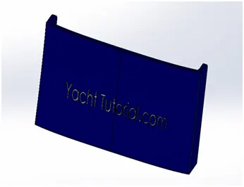
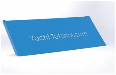
The garage is located at the bow of the yacht. The garage door is used to close the garage space in the yacht. The opening mechanism of the garage door can be mechanical or electrical. The garage is normally used in the yacht for the storing cars, bikes, paddle boards, dive gear, inflatable mats, jet skis, sea bobs etc.
Features used to model the Garage door
- Sketch
- Cut Extrude
- Shell
- Fillet
- Mirror
- Reference Geometry(plane)
Seats
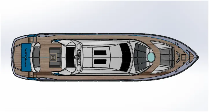
The seats are; located at the front, middle and rear of the hull for the recreational purposes. It is the place for enjoying the view of the sea from the yacht. The front seats can accommodate three persons. there is Jacuzzi pool at the front which is a large hot tub full of water used for hydrotherapy, relaxation or pleasure.
The middle seats also have a table which can be used for dining purposes or having parties. It can accommodate six persons. The rear seat also provides a great view. The seats are generally made of high quality materials for great comfort and luxury. There is flag to give out signals or for aesthetic purpose.
Front seat
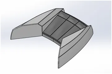
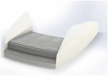
Features used to model the front seat
- Blue print set up
- Sketch
- Swept surface
- Trim surface
- Filled surface
- Lofted surface
- Knit surface
- Chamfer
- Revolve
- Extruded cut
- Fillet
- Mirror
- dome
Middle seat
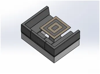
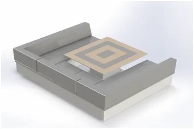
Features used to model the middle seat
- Blue print set up
- Sketch
- Extruded boss
- Reference geometry (plane)
- Chamfer
- Fillet
- Mirror
- Extruded cut
Rear seat
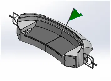
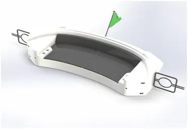
Features used to model the middle seat
- Blue print set up
- Sketch
- Swept surface
- Trim surface
- Ruled surface
- Lofted surface
- Extend surface
- Knit surface
- Extruded boss
- Extruded cut
- Chamfer
- Fillet
- Reference geometry (plane)
- Offset surface
- Swept boss
- Mirror
- Revolved boss
Superstructure
A superstructure is an extended construction of any building or platform that rises above the rest of the building or platform in a distinct manner. The word comes from a combination of two Latin words, the Latin prefix ‘super’ means above of, whereas the stem word ‘structure’ means to build up. This is designed uniquely since it provide the identification of the yacht. It is designed in a way that it does not hinder the mobility of the vessels. It also provides space and room for the passengers for recreational and exercise.
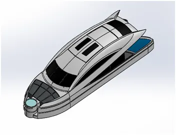
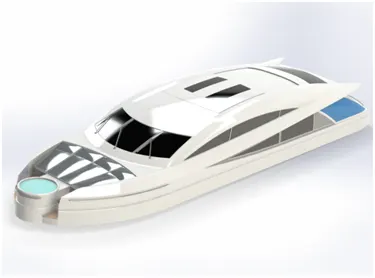
Features used to model the Superstructure
- Blue print set up
- Sketch
- Extruded surface
- Offset entities
- Trim
- Reference geometry (plane)
- Swept surface
- Ruled surface
- Trim surface
- Projected curve
- Filled surface
- Knit surface
- Lofted surface
- Extend surface
- Extruded boss
- Fillet
- Offset surface
- Thicken
- 3 d sketch
- Dome
- Swept boss
- Extruded cut
- Split line
- Extruded surface
- Mirror
- Chamfer
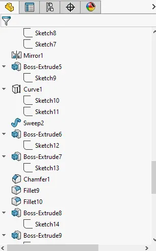
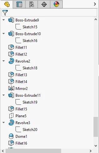
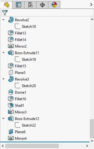
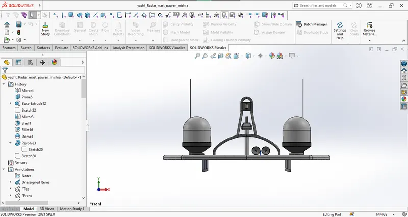
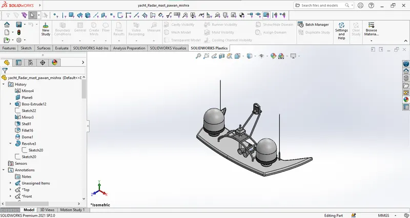
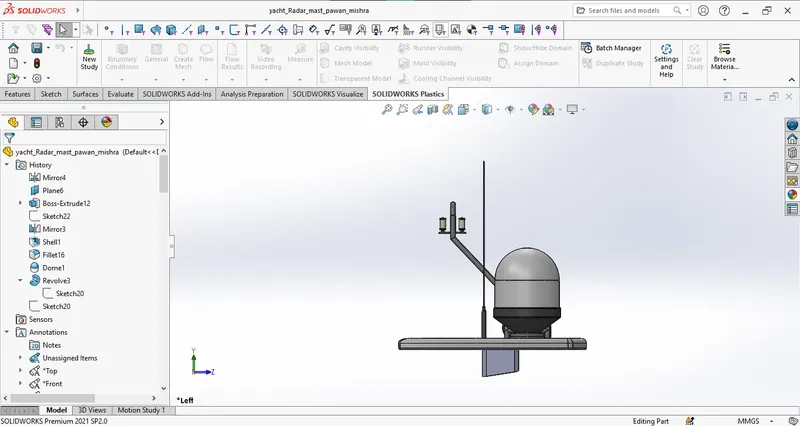
Radar mast
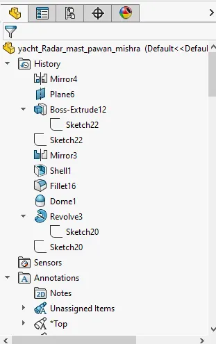
Mast is the tall pole that holds up the sails and radar on a ship.
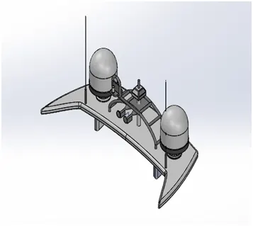
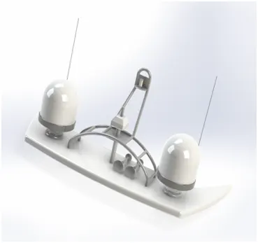
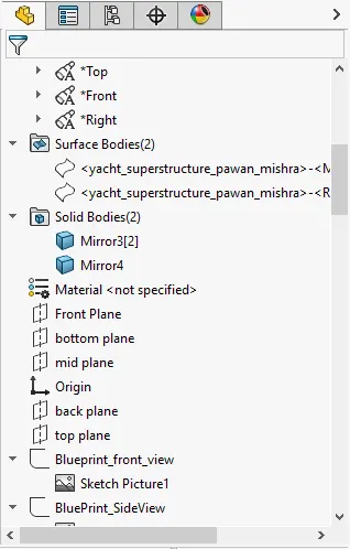
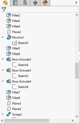
Features used to create Radar mast
- Blue print set up
- Sketch
- Extruded boss
- Fillet
- Revolved boss
- Reference geometry (plane)
- Swept boss
- Mirror
- Chamfer
- Dome
Assembly
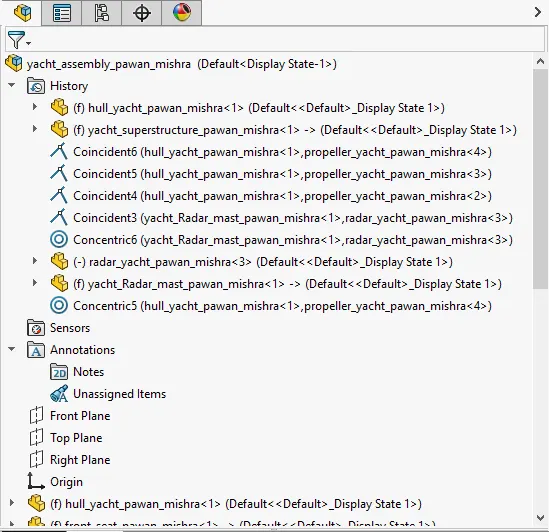
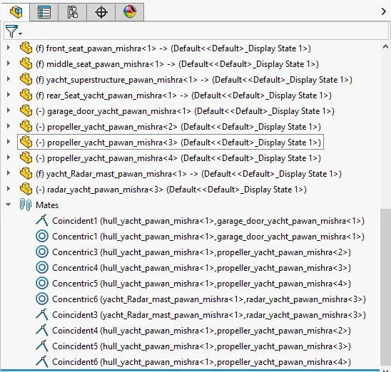
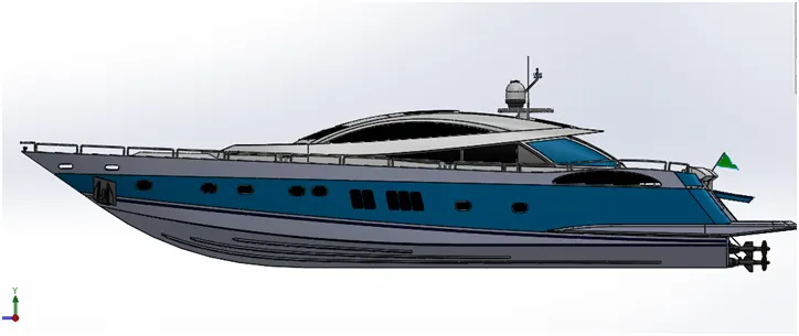
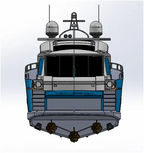
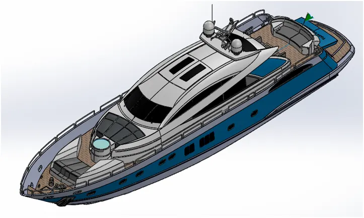
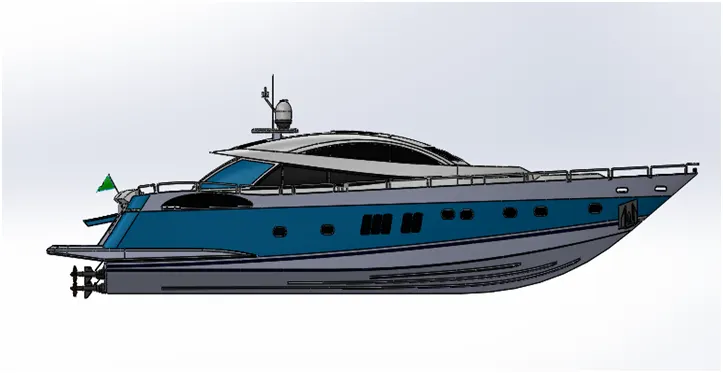
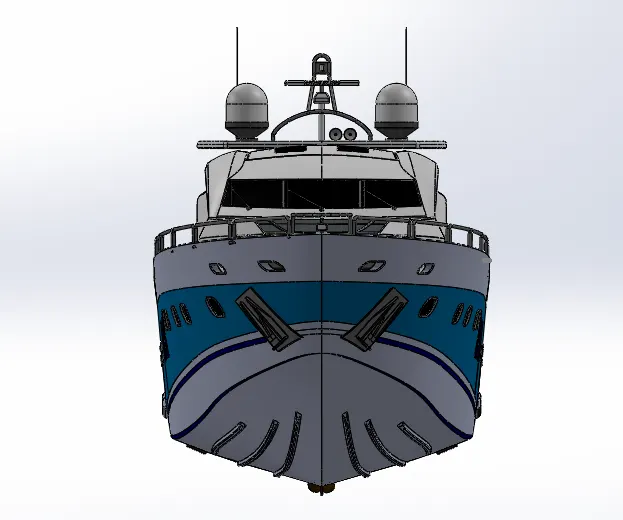
The parts were inserted into the assembly environment and assembled using appropriate mates.
Mates
Mates are used to create geometric constraints between assembly parts, we can define the linear and rotational movements of the components. We can move a component within its degrees of freedom, visualizing the assembly's behavior. For example coincident, parallel, concentric, etc.
Rendering
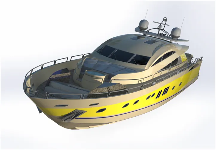
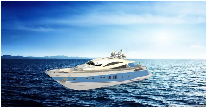
Rendering or image synthesis is the process of generating a photorealistic or non-photorealistic image from a 2D or 3D model by means of a computer program. In this project the rendering is done with photoview 360 and solidworks visualize. The decals were added to the models like gas tank, rear fender to give them better look.
PhotoView 360
This is a SOLIDWORKS add-in that produces photo-realistic renderings of SOLIDWORKS models. The rendered image incorporates the appearances, lighting, scene, and decals included with the model.
Solidworks visualize
It is used to create photo-quality content in the fastest and easiest way. We can form images to animations, interactive web content, and immersive Virtual Reality. Bring our products to life
Rendered images
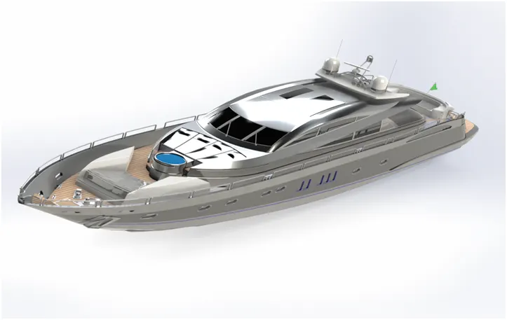
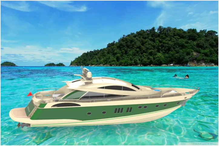
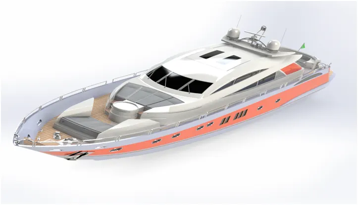
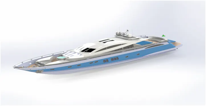
Conclusion
The parts of the yacht were modeled individually with fully constrained sketches and the parts were inserted into the assembly environment. The yacht was assembled using the appropriate mates. Then the decals were added to the models like hull main floor, steps etc to give them realistic look. The suitable appearances were added to individual parts to give them better look. Then the photo realistic render was created using the solid works visualize and photo view 360. Thus a better understanding of solid works tools and features was achieved.