Advanced Sheet Metal Design Using NX Cad Challenge_6_Bracket
Title: Advanced sheet metal design using NX Cad:- Bracket
Objective
- The objective of this project is to design the Bracket using the Siemens NX Cad software’s sheet metal application.
- To learn and understand use of various tools used in sheet metal design.
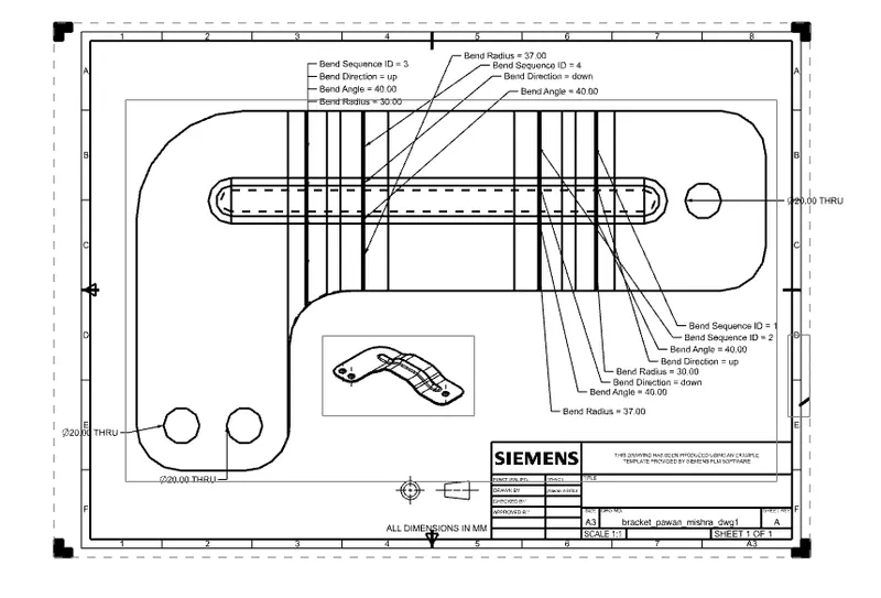
- To make a draft of the Bracket modeled.
Introduction
Sheet metal is a type of metal which is formed into thin sheets by various industrial processes. It’s thickness varies from 0.5mm to 6mm. It is widely used in Automobile, Aerospace, roofs for buildings and so on, the most commonly used metals are aluminum, steel, tin, etc.
Sheet metal Enclosures are used to resist corrosion and provide electrical conductivity. The product is widely used for various industrial purposes.
Design Methodology
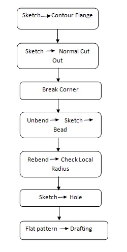
Description of tool and features
Contour Flange
This tool is used to create a base feature by extruding a sketch along a vector, or adds material by sweeping a sketch along an edge or chain edges.
Normal Cutout
This tool is used to cut the material by projecting a sketch onto the model and cutting perpendicular faces intersected by the projection.
Unbend
This tool helps to flatten a bend and the material adjacent to the bend so that the holes or other features can be created.
Bead
This tool is lift an area around a contour which simulates the stamping tool.
Rebend
This tool is used to restore an unbend feature to its previous bent state, along with the features added after unbend feature.
Flat pattern
This tool is used to create a flat pattern from the formed sheet metal part.
Drafting
Drafting is used to convert 3d models into 2d technical drawings.
Hole
This tool is used to create holes of various type like screw type, counter bore, counter sink etc.
Model Images
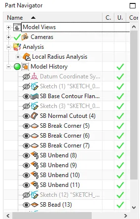
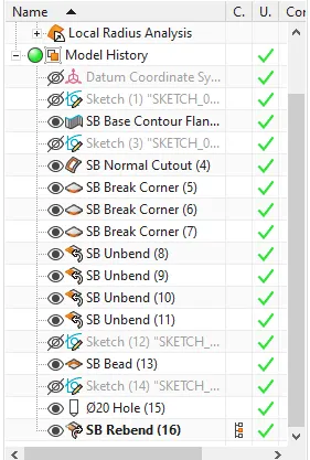
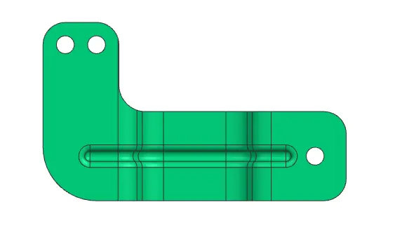
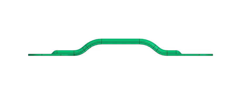
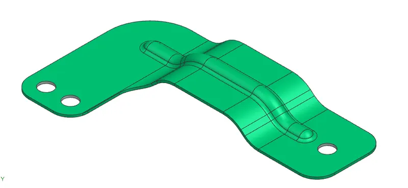
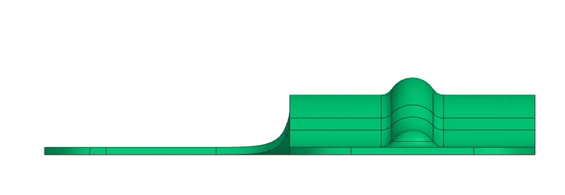
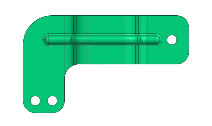
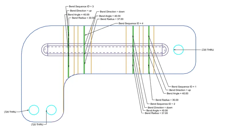
drawing image
Conclusion
Thus tools and features in Nx Cad sheet metal application were understood and the bracket was created and the model was drafted.