Week 1:- Introduction to BiW and Fixtures Challenge
Introduction to BiW and Fixtures
Aim
To study the basic concepts of BIW and its fixture design
1.BIW and its parts
BIW
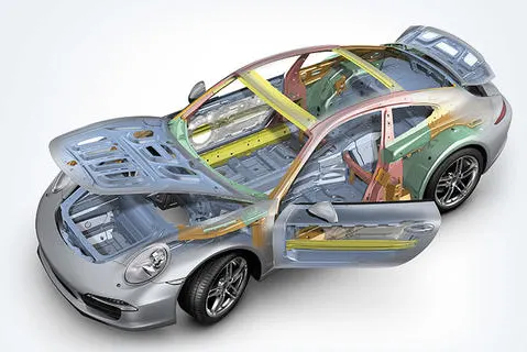
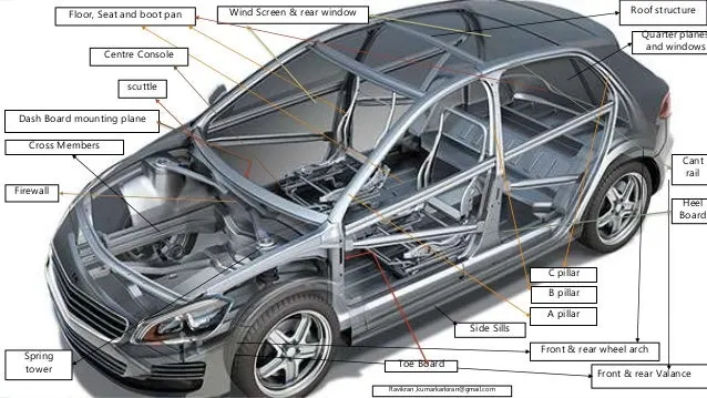
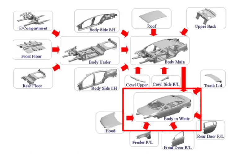
- Body in white (BIW) is the stage in automobile manufacturing in which a car body's frame has been joined together.
- It is a stage in car assembly before painting, motor, chassis sub-assemblies, or trim like glass, door locks/handles, seats, upholstery, electronics, etc.have been integrated into the structure. Assembly involves different techniques such as spot, MIG/TIG welding), riveting, clinching, bonding and laser brazing.
- Biw are welded sheet metal components which form the vehicles structure to which the other components will be married, i.e., engine, chassis, exterior and interior trim.
- Examples- hood, roof, fender, side doors etc.
- steel and aluminum have been used for making BiW; the steel is preferred for its high strength and low cost, aluminum is preferred for its lower density that helps reduce car weight.Modern super cars used reinforced carbon fiber owing to its superior mechanical properties.
- The BIW contributes about 25%to 30 % of the car's weight.
Function of BIW
- To provide safety to the occupants and pedestriants in the event of crash by absorbing the impact energy.
- To minimize the drag and improve the aerodynamics of the car.
- To insulate the occupants in the car from the NVH from the transmission and road noise.
significant properties of BIW material
- It must have high tensile strength as well as high stiffness-bending, torsional, static, and dynamic.
- It must also provide good quality safety both to the car body and to its occupants against crashes of all kinds—front, rear, side, or even rollover, meeting the Motor Vehicle Safety Standard.
- It should also be able to protect occupants from noise, vibration, and/or harshness (NVH) by absorbing or reducing these conditions.
- It should be easy to weld and form, highly paintable and easy to design.
- It should provide a good smooth surface finish.
- It should be corrosion resistant.
- It should also be recylable to be environment friendly.
BIW Types
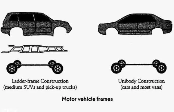
Body on Frame Construction
- Body is mounted on a separate chassis / frame
- Used in utility vehicles, trucks, buses
- Wheels and suspension are mounted on chassis
Monocoque construction (Chassis in built in Body)
- Chassis is inbuilt with BIW itself and there is no separate chassis
- Used in all the passenger cars and to some extent in utility vehicles
- Wheels and suspension are directly mounted to BIW.
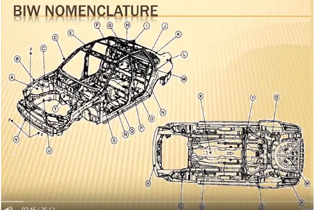
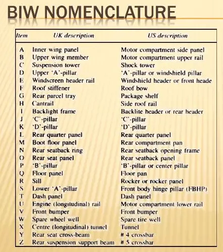
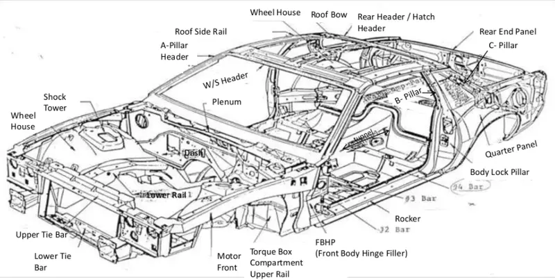
BIW parts
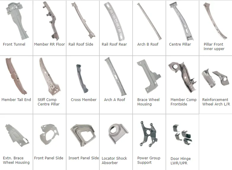
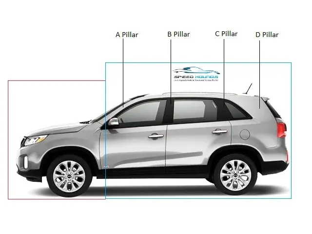
- Underbody structure
- Front end structure
- Body side structure
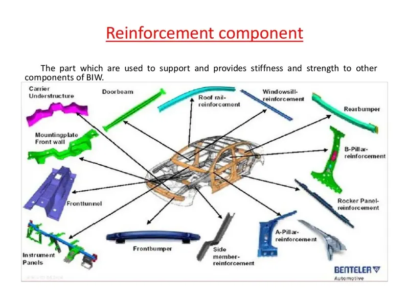
- Reinforcement
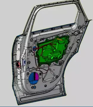
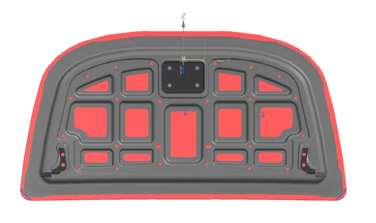
- Side closures
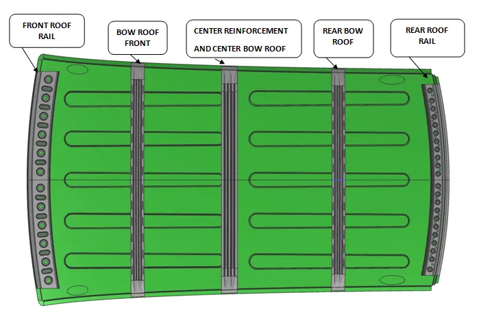
- Roof
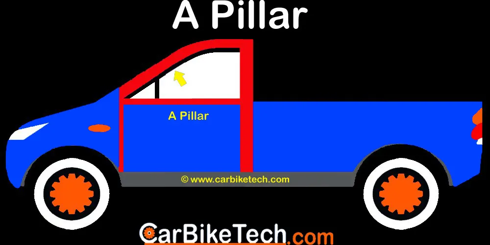
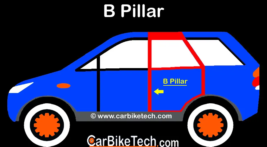
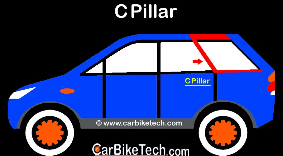
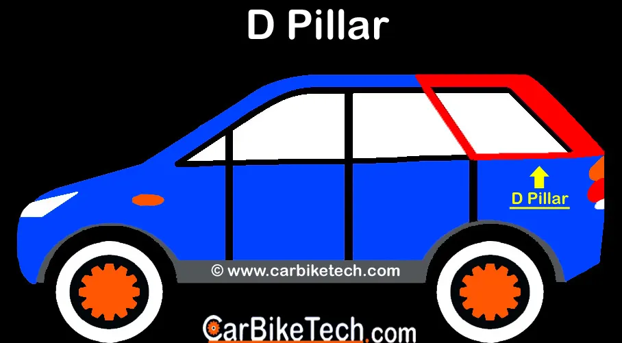
3.Fixture and its types
Fixture
A fixture is a work-holding or support device used in the manufacturing industry. They are used to securely locate (position part in a specific location or orientation) and support the workpiece The fixture should maintain conformity and interchangeability between the produced parts.The fixture does not guide the tool.It also consists of work holding device, which is clamped on the machine able to hold the work in the position. The tools are set at the required positions on the work by using gauges and minor manual adjustment.
Main elements of Fixtures
Body: It is a plate, box or frame type structure in which the components to be machined are located. It should be quite sturdy and rigid.
Locating elements: These locators locate the workpiece in a proper position in relation to the cutting tool.
Clamping elements: The clamps holds the workpiece firmly in the located position.
Guiding and setting elements: These elements guide the cutting tool in case of jig and help in proper tool acting in case of the fixture.
Positioning elements: These elements include different types of fastening devices which are used in securing the jig or fixture to the machine at the proper position.
Indexing elements: They are provided when the workpiece has to be indexed to different positions in order to perform machining operations on different surfaces or different locations.
Types of Fixtures Used in Manufacturing
- Turning fixtures.
- Milling fixtures.
- Broaching fixtures.
- Grinding fixtures.
- Boring fixtures.
- Indexing fixtures.
- Tapping fixtures.
- Duplex fixtures.
- Welding fixtures.
- Assembly fixtures.
Types of BIW Fixtures
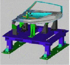
Pre-Production Fixtures
This fixture are used to check the feasibility of batch production before the fixture design is finalized. It is a kind of prototyping fixture used to check the functionality and precision of the fixture designed. These fixtures are used to verify the errors and can be used as an benchmark to design the production ready fixture. To check the functionality of the fixture operators, production engineer, quality control engineer work together to find any flaws within the fixture. It is done step by step and so it has a comparitevly longer cycle time. But designing a pre-production fixture is not common in these days due to high cost and time associated with it. The engineers try to make the production with as many standard parts as possible to avoid any misalignment or deviation.
Production Fixtures
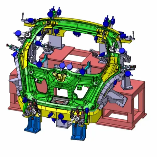
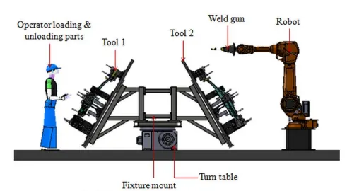
This fixture is designed with great care after complete study of the part to welded. This fixture is used in main production line. It should be able to provide precise location and adequate clamping to the part to get the required dimensions and tolerances. The clamping must onle provide the adequate clamping force and must not leave any impression on the part. The locators must locate precisely and arrest all the degree of freedom of the part.It should be designed to prevent distortion in the welded part.The base of the fixture must be rigid and stable. The ergonomics of the operator for loading and unloading the part is also studied and optimized to improve the productivity and time required to process the part. It is mainly used in automated assembly line.The robotic welding arms with various grippers and tools are used to complete the joining process. The operations like welding,hemming,gluing and fastening. The parts are checked randomly and if no errors were found the process runs continuosly. The fixture has to be maintained peridically to check by the quality control for any misalignments.
Checking Fixtures
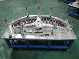
This fixture is used for geometric inspection of the manufactured part. It checks the various dimension and tolerances with help of coordinate measuring machine(CMM), The data is compared to the CAD drawing/GD&T sheet to ensure proper dimensions are met . It is not used in the main production line. It is used to check the assembly of automotive seats and the positions of the mounting and locating holes. It is also used in checking the orientation of the mounting legs of the seat.
Hemming Fixtures
This fixture is used to join the inner panel and outer panel of the automotive BIW parts.
Roll hemming fixture
Material used for making the Fixtures:
- Grey cast iron
- Hardened steel
- Plastic
- Stainless steel
- Bronze
- Carbide
Desing Principles
Design principles of fixtures
Rigidity
The fixtures should be sufficiently stiff to secure the preset accuracy of machining.
Fool proofing
It is the incorporation of design feature in fixture that will make it impossible to lead the work into the fixture in an improper position and also not interfere with loading and unloading the work piece.
Clearance
Clearance is provided to allow for any variation in component sizes specially in casted and forged parts. To allow hand movements so that the work piece can easily placed in the fixture and removed after machining .
Ejectors
The use of ejection devices to force the work piece out from the fixture when the work piece is heavy or when machining pressure forces and oil or coolant fill will cause the work to get stuck and difficult to remove.
Inserts
To avoid any damage to fragile and soft work piece and also to the finished surfaces of the work piece while clamping. Inserts of some soft material such as copper, lead , fiber , leather , hard rubber and plastic should be fitted to the faces of the clamps.
Design for Safety
Sharp corner on the body of jig and fixture should be avoided. Bolt and nut should be inside the body of jig or fixture and not protrude on the surface.
Sighting Surface
Machining on the work piece must be clearly visible to the worker. He should not be required to bend is neck for seeing the work piece or work surfaces.
Simplicity in design
They should be easy to set and cheap to manufacture.
Economical
A fixture should be simple in construction, give high accuracy , be sufficiently rigid and lightly weight.
- Resting - Stability
- Locating - W.r.to datum
- Orienting - W.r.to secondary datum
- Clamping - Ensuring above conditions not disturbed.
Advantages of fixtures
- It increases the machining accuracy and also increases production capacity.
- Requires less skilled operation.
- They reduce the production cost.
- Increases the quality of production in the industry.
- They enable the quick setting of a tool and the proper positioning of the work.
Disadvantages of Fixtures
- It Can have wear and tear over time.
- The high initial set up costs.
- It uses a lot of material and is bulky.
Applications of Fixtures
- Mass production of automobile parts.
- Inspection of parts in continuous production in manufacturing industries.
- Cutting the ingots in the steel plant.
- Pump assembling process
- For drilling the flanges and drilling holes to any required angles.
4.Basic Principle used in the Fixture Design
3-2-1 Principle
The 3-2-1 principle is the basic principle used in BIW fixture design. It is used to lock all six degree of freedom of the workpiece. It is a Component holding principle where three pins are located on any of the 1st principle plane(XY, YZ, ZX). And two pins are located on the 2nd plane which is perpendicular to the 1st plane, and at last one pin on the plane which is mutually perpendicular to the 1st and 2nd planes.By using this method Componet movement can be arrested in all six degrees of freedom.
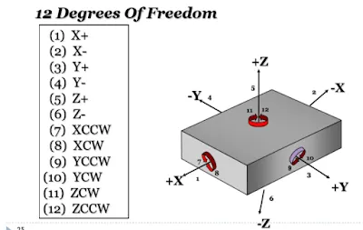
The Location of a part to be machined involves mainly three steps: Supporting, Positioning, and Clamping. Every free body has a total of twelve degrees of freedom 6 translational degrees of freedom and and 6 rotational degrees of freedom(+X, -X, +Y, -Y, +Z, -Z). All the 12 degrees of freedom except the three transitional degrees of freedom (-X, -Y and -Z) must be fixed in order to locate the work piece in the fixture.
Locators used in 3-2-1 principle
Primary Locators
It arrests 5 DOF. Three primary locators are placed under the work-piece, it it also known as datum.
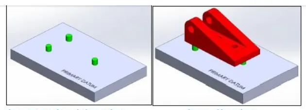
It stops Axial Movement downward along Z- axis and Rotation about the X and Y axis in both directions.
Secondary Locators
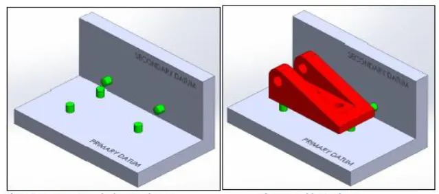
Tertiary Locators
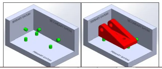
In the assembly line the car panel/car body parts are joined and the semi finished assembly moves from one station to another station until the final product is produced.In the process of joining in assembly line , panels are moved from one section to another sections.Those sections are called Stations. In BIW fixture designing we have various stations which are used to locate the panels so that joining processes can be done.
Lock and Dock Station
A station where the Car part is held by a gripper and the complete gripper is located and clamped. Normally a Robot unloads a gripper along with the car part and operations such as stud welding are done before the robot picks up the gripper.
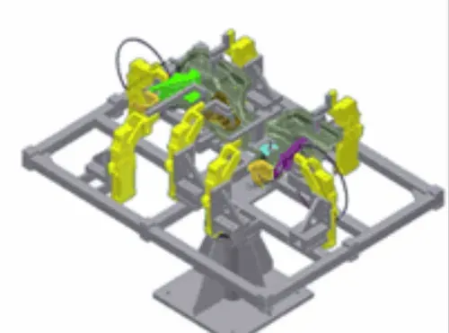
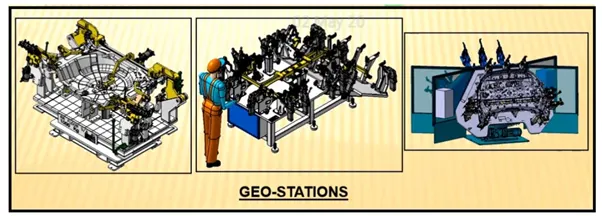
In geo station geometry of the two parts are fixed. it can be done by using welding or riveting . The Locating pins with closer tolerence of 0/-0.15 mm are used to define the precision and geomatry of the finished product. To achieve precise dimensions diameter of locating pins should be lesser than the panel hole dia. So Tolrence in locating pin is given in negative value.The individual panels of the product are accurately stacked in the Geo station and are spot welded. The MIG welding can also be used in continuous weld seam is used.
Example: if the hole dia of panel is 8mm then the pin dia should be 7.85mm(min).
Covel Cover geo-spot welding fixture
Respot Station
After the product comes out of the Geo Station with the left out spots of spot welding or riveting is then moved to Re-spot station.These left out spots may be the due to clamp plan, cycle time,robot reach ability or any other various reasons. It can also be due to high number of spot welds to be done. The re-spot station completes the incomplete work from the geo station and ensure the continuous operation of the assembly line. The locating pins in this station can have tolrence range of 0/-0.28mm.
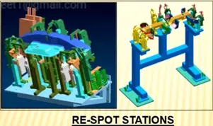
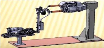
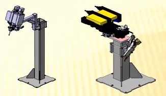
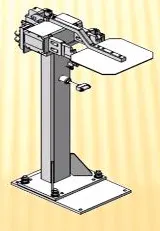
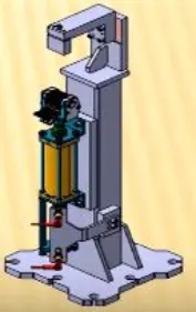
In this station , Pedestal gun is mounted on a tool and panel is manipulated manually or by robot to weld the panels. Pedestal station is generally a Re spot station. Re spot station and Pedestal station, both perform same kind of operation . but to decide whether to go for pedestal or a re-spot station some parameters needs to consider like cycle time, floor space, no. of welds, clamp plan, or size of the panel.
Loading Station
This station is used for loading of panel and to change the orientation of the if it is required in the next station. Sometime this station is used when Robots are unable to transfer panel from one station to another.
Gripper Station
The grippers are devices that enable robots to pick up and hold objects. It is combined with industrial robot arm to enable automated functioning of the key operations like inspection, assembly, pick and place and machine tending. Machine tending refers to the automated operation of industrial machine tools in a manufacturing plant, primarily using robot automation systems
For example
- Vacuum grippers
- Pneumatic grippers
- Hydraulic grippers
- Servo-electric grippers
Types of grippers used in the gripper station
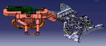
Process Gripper
This type of grippers are used to do operations like welding, gluing, riveting and can aslo be used for material handlng.
Material Handling gripper
These grippers are used for handling the BIW panels from one station to another in the assembly line.
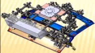
Dual gripper
This an gripper+gripper arrangement used for material handling between stations. It is used to handle larger parts.
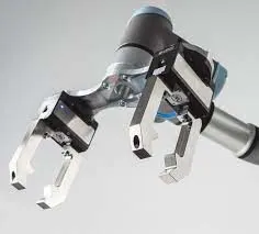
combo gripper
This is combination of gripper+welding gun. The same robotic arm can use the weling gun to do spot welds and replace it with another gripper and do material handling to move panels from one station to another.
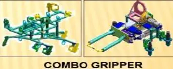
This station is used to make the balance between the process. Some stations carry out procees in lesser time as compared to their respective stations. In that case panels can be stored in one sation so that assembly line process remains smooth. The buffer stand is used for storage purpose. It can be done to store the inventory or excess part produced when the some machine in is maintenance in the assembly line.
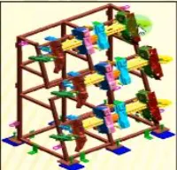
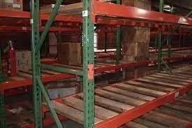
Racks
The place where the panels are kept ready to be used in the assembly process. It has part details like name, part model number, for correct usage of part for the assembly.
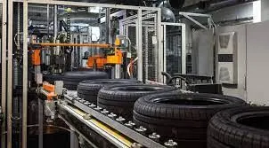
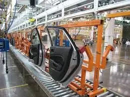
Conveyors
The conveyors are used to transport the parts from one station to another. It may be chain or belt type
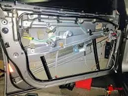
In this station Sealant application is carried out.This process can be carried out manually or by using robots. Sealer is used in between two panels so that panels do not flatter due to friction.
It is also known as the hemming station. In this Station inner and outer panels are joined.This station is normally situated between a Gluing and a Hemming station. In order to avoid the imprssion on the outer panel(A class surface), copper strips are used in between the weld tip and A-class surface.Ex: Doors, Liftgates, Body sides, etc.
Roll hemming Robot
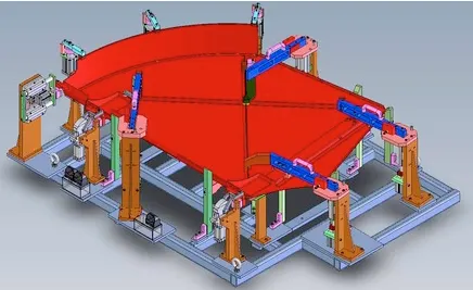
Framer Station
It is located next to the marriage station. The roof of the biw is attached in this station so it is called as framer station.
Curing Station
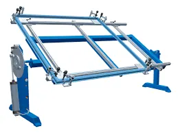
In this Station product recieved after sealing application, is kept idle at ambient temperature, which allows sealent to get dry with better bonding between the panel.
6.Basic terminologies used in the BIW fixture
Shims
Shim is a set of thin plates that are used to adjust the gap or used for a better fit. Shimming can be of thickness (2 mm, 1mm, 0.5 mm, 0.25mm, 5mm, 8mm, or 10mm). If proper fitting between mylar and Panel due to manufacturing errors then this error can be removed using shims. Shims are placed in the carline position so that gap can be adjusted in the required direction like X, Y, or Z.
Types of shimming
- One-way.
- Two-way.
- Three-way shimming.
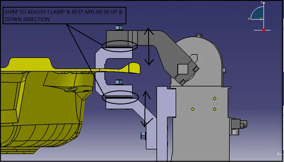
Number of shimming depends upon the NC cut angle and PIN angle with the car line.
- If NC cut is less than 15 deg then mylar will have one-way shimming.
- If NC cut is more than 15 deg in one direction then mylar will have a 2-way direction shimming
- If NC has more than 15 deg angle in two directions then mylar will have 3-way directional shimming.
In case of pins
- If the pin is on the angle with respect to the carline not more than 15 deg then the pin will have 2-way directional shimming
- if Pin’s angle is more than 15 deg in any direction then 3 shimming will be used.
Shim solid and Shim pack
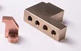
MYLAR is a block that touches the panel and holds or clamps the panel. Mylars are always designed in CAR LINE. Mylar is also called NC(Numerically Controlled)Block or fingers. Mylars can be mounted on any block or plate with Shimming to adjust the height of mylar according to the assembly. For ‘A’ class surfaces Nylon mylars are used. So that surface can be saved from scratches. The mylar should not produce any deformation or mark during the weelding process.
Types of Mylars
The both type of mylars must be used in a clamp unit.
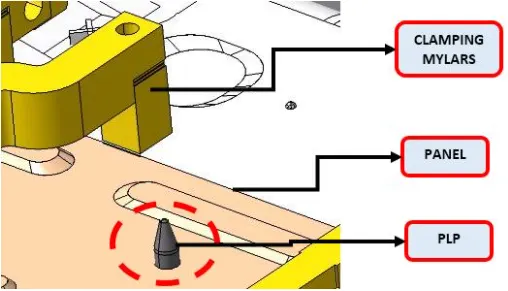
Clamping Mylars
These mylars are used to hold the panel from the top.
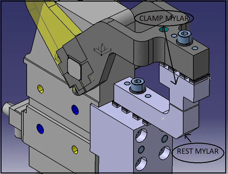
Resting Mylars
The part rests on this mylars and located below the clamp mylar.
Pins are used to locking the rotational movement of the panel. Generally there two types of Pins, one is Round Pin and another one is a Diamond pin. The two and three-directional shimming are used for pins as per the angle of the pin with respect to the carline. In some cases a collared pin is used when the pin is supposed to support the panel as well. For this kind of pin 3 way shimming is provided irrespective of pin angle to the carline.
- Location Round Pin- Pin used to location BIW sheet metal parts. It is also called as 4 way pin and can restrict motion in 4 directions.
- Diamond Pin- Pin has diamond shape when seen from top view. It is Used to restrict only 2 direction.Mostly referred as 2 way pin.
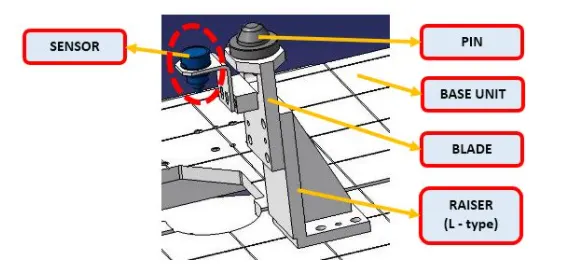
The plate which connects Riser to the Clamp cylinder is named Blade. This plate plays an important role in building the unit. The plate can be of any shape. This plate should be as compact as possible.
A plate shaped as L is called an L block. This part is used as a connection between mylar and Blade. Generally, L blocks are used to provide shimming. It can also be used connect one part to another. A T block can also be used based on the application.
Pin Block is also called Pin Retainer. This block holds the pin and restricts the rotational motion of the pin. Pin Block can be either manufactured one or Standard onees can be used.
The part which is mounted on the base plate and holds a toggle clamp, rest clmap or pin cylinder on it, is called Riser. Riser can be Standard Part or manufactured part, it varies from project to project. A riser can be a Single part or welded part. Standard risers also have various shapes and sizes.
Weldment is the assembly of two or more parts that are joined by welding. A thumb rule to have a 5 mm overlay on each other plates so that space can be provided for welding is used. A weldment can be of any size and any number of plates.
- 2 Metal Spot- Resistance spot welding to join sheet 2 metal parts
- 3 Metal Spot- Resistance spot welding to join sheet 3 metal parts