Photo Realistic Rendering
MODELING OF AMERICAN CHOPPER IN SOLIDWORKS
Introduction
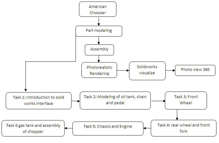
This project is part of ultimate solidworks course in skill lync, Solidworks is used for planning, visual ideation, modeling, feasibility assessment, prototyping, and project management. In this module I have learnt how to make 2d sketches of the parts of an American Chopper and convert it into 3d models using various tools. Then the parts were assembled using the appropriate mates. Finally an photorealistic render was created using soliworks visualize and photoview 360
Objective
- To create fully defined sketches and model parts of chopper In solidworks.
- To create assembly of American Chopper.
- To learn how to apply decals, add and edit materials.
- To understand the application of lights, camera, in rendering.
- To create and photorealistic render of the American chopper using photoview 360 and solidworks visualize
Design methodology
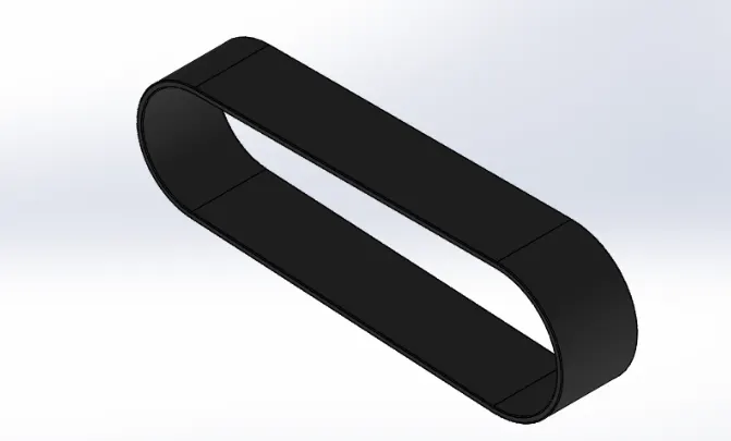
Transmission Belt
The transmission belt is used to transfer the power from engine to gear box.
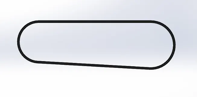
Features used to create Transmission belt
- Sketch
- Offset Entities
- Boss Extrude
- Fillet
- Edit Appearances
Sketch
Sketch is 2D representation of 3d models and it is created using sketch entities like line, circle, arcs, spline, polygons,etc
Offset entities
Offset one or more sketch entities by a specified distance. If the original entity changes then the offset entity also changes when you rebuild the model.
Boss Extrude
Extrudes a sketch or selected sketch contours in one or two directions to create a solid feature. Extrude can also be offset to specified distance.
Fillet
Creates a rounded internal or external face along one or more edges on a solid or surface feature. Fillets can be of constant or variable size.
Edit Appearances
Edit the appearance of the entities in the model using appearance properties such as texture mapping and colors. In this model matte rubber was chosen.
Kick stand/ side stand
It is used to support the chopper while parking it
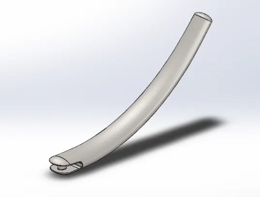
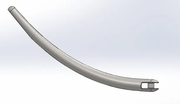
Features used
- Sketch
- Lofted Boss
- Dome
- Extruded boss
- Extruded cut
- Fillet
- Split
Lofted Boss
This feature adds material between two or more profiles to create a solid feature. It helps to generate complex geometries
Dome
This feature can be used on planar or non-planar surfaces to get a closed curved surface.
Extruded cut
This feature is used to remove materials from a solid model by extruding a sketched profile in or two directions. In multi body parts we can choose body to cut and bodies to keep.
Split
This tool is used to project an entity onto other curved or planar surfaces. We can create multiple bodies from single body.
Front fender
The front fender is used to prevent the mud, sludge or debris thrown around the wheel. It covers the top half of the front wheel and mounted on the front fork.
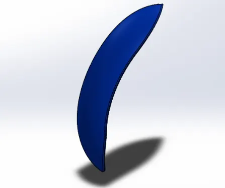
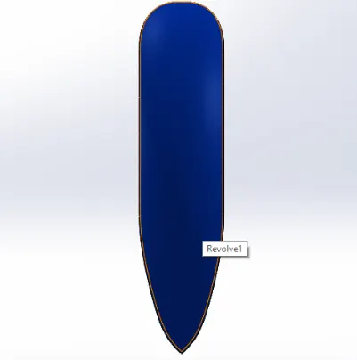
Features used
- Sketch
- Offset entities
- Revolved Boss
- Trim entities
- Split
- Dynamic mirror
- Appearances
Revolved Boss
Revolves a sketch or selected contours around a axis to create a solid feature. We can define axis of revolution and direction.
Dynamic mirror
This feature mirrors entities dynamically about a centerline.
Trim Entities
Trims or extends a sketch entity to be coincident to another or deletes a sketch entity.
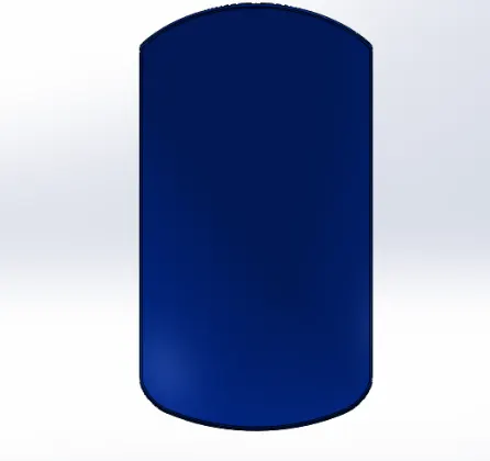
Rear Fender
This has similar functionality to the front fender and it is mounted on the chassis above the rear wheel.
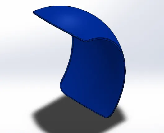
Features used
- Sketch
- Revolved boss
- Trim entities
- Fillet
- shell
- Appearances
Shell
Shell feature hollows the part and leaves the face open which you select and creating thin walled features on the remaining surfaces. If a face is not selected then a closed hollow model is created
Chain
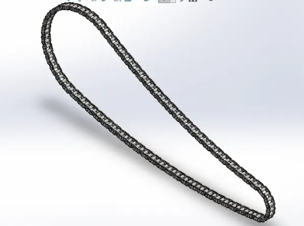
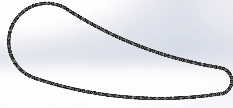
The chain is the part of the power train which transmits the power from the engine to the rear wheel and it connects the two sprockets on the front and another on the rear.
Features used
- Sketch
- Sketch Blocks
- Trim
- Extruded boss
- Fillet
- Curve driven pattern
- Mirror
- Appearances
Sketch Blocks
These are saved set of sketch entities which can be reused whenever required. The chain links were created as sketch blocks and reused.
Curve driven pattern
This tool helps us to create patterns along a planar or 3D curve. This pattern is defined using sketch segment or the edge of the face. We skip pattern instances and pattern in one or two directions.
Mirror
Mirrors features, faces, and bodies about a plane or a planar face. In assemblies you can mirror assembly features
Oil tank
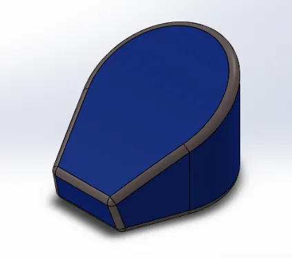
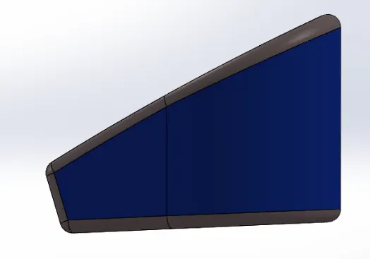
The oil required to run the engine is stored in the oil tank. It is located below the seat. This is an hollow part with 3mm thickness.
Features used
- Sketch
- Extruded Boss
- Combine
- Fillet
- Shell
Combine
Using the combine tool we can add, subtract, or find common area of two different bodies. A multi body part is required for this feature. In this model two different boss extrudes common area was chosen.
Pedal
The riders keep their foot on pedals when the chopper is moving to retain control and balance
-
.
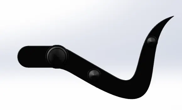

Features used
- Sketch
- Boss extrude
- Fillet
- Revolve
- Dome
- Chamfer
- Linear pattern
Linear pattern
This feature patterns features, faces, and bodies in one or two linear directions. This can be defined by selecting reference geometry and instances can be skipped.
Chamfer
This feature is used to create sloped or angled corner or edge. It can be defined by either choosing distance distance or angle distance option.
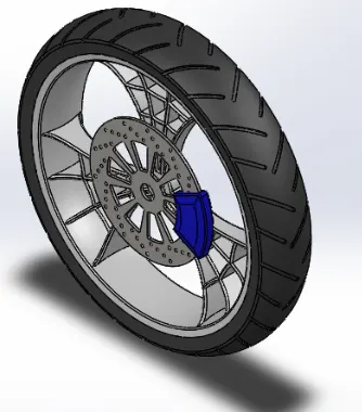
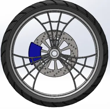
Front wheel
A wheel is a circular block of hard and durable material which has a bored hole at its centre in which the axle bearings go and the wheel rotates when the torque is applied, the wheel is covered by tire which is made of rubber material. It also houses the brake rotor and brake caliper.
In this model spider web rim design is chosen.
-
Features used
- Sketch
- Sketch fillet
- Revolved boss
- Boss extrude
- Revolved Cut
- Circular pattern
- Fillet
- Chamfer
- Extruded cut
- Linear pattern
Circular pattern
This feature is used to make pattern of features based on circular reference. We can define the instances, spacing, and angle.
Revolved cut
This feature is used to cut a solid model by revolving a sketched profile around an axis. In case of multi body parts we can select bodies to keep.
Rear wheel
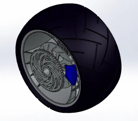
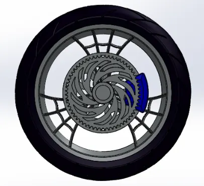
The rear wheel is a circular block of hard and durable material which has a bored hole at its centre in which the axle bearings go and the wheel rotates when the torque is applied, the wheel is covered by tire which is made of rubber material. it houses the rear sprocket, brake rotor and brake caliper.
Features used
- Sketch
- Boss extrude
- Cut extrude
- Circular pattern
- Combine
- Reference geometry(plane)
- revolved cut
- fillet
- chamfer
- revolved boss
Front fork
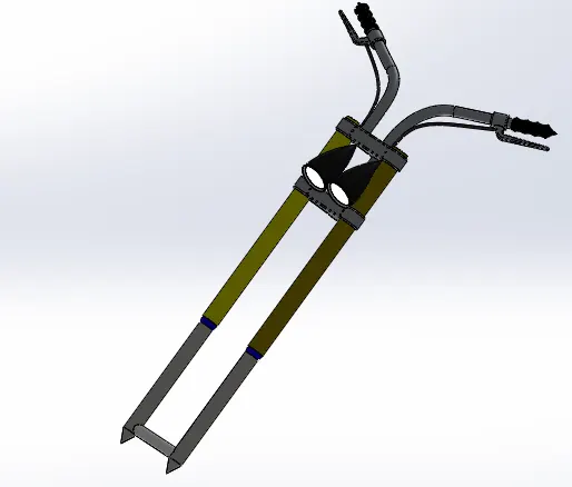
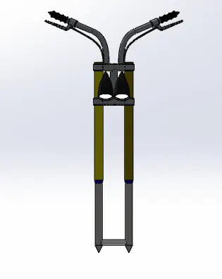
The telescopic front suspension is universally used front suspension in two wheelers. The telescopic fork uses fork tubes and sliders which contain springs and dampers. It is simple in design, easy to manufacture and low in cost.
Features used
- sketch
- Revolve
- Extruded boss
- Fillet
- Trim
- Linear pattern
- Extruded cut
- Dome
- Move/copy bodies
- Swept boss
- Splines
- Projected curves
- Composite curves
- Reference geometry (planes)
- Mirror
- Combine
Move/copy bodies
The Move/Copy Body tool in SolidWorks is useful when a part is needed to be shown in multiple configurations. The Move/Copy Body tool takes a body, copies it, and moves it to the desired location
Projected curves
This feature is used to create 3D curve from 2D curves from two different curves.
Composite curves
It is formed from a combination of curves, sketch geometry, and model edges
Swept Boss
This feature sweeps a closed profile along an open or closed path to create a closed surface. A wide variety of shapes can be created by using the options like guide curves, twist and profile orientation options.
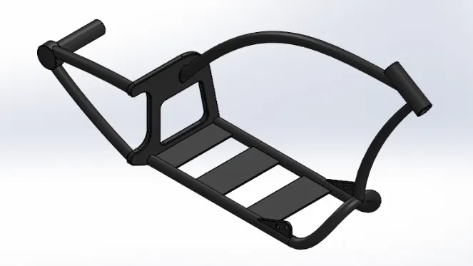
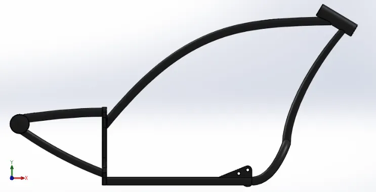
Chassis
This is mainly made up of hollow tubes of aluminum or steel. This serves as the skeleton for mounting the components like engine, gear box etc. the chassis helps to maintain good handling and support suspension system
Features used
- Sketch picture
- Sketch
- Projected curves
- Composite curves
- Sweep
- Trim
- mirror
- Extruded boss
- Extruded cut
- Chamfer
- fillet
- Dome
- Reference geometry (planes)
- Split
- Combine
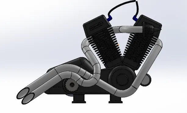
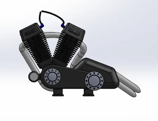
Engine
An engine or motor is a machine designed to convert chemical energy into mechanical energy. The mechanical work in form of rotational motion is transmitted to the wheels with help of gear box, clutch, chain and sprocket.
Features used
- Sketch picture
- Sketch
- Boss extrude
- Fillet
- Revolved boss
- Circular pattern
- Dome
- Cut extrude
- Chamfer
- Linear pattern
- Split
- Mirror
- Swept boss
- Combine
- Projected curves
- Composite curves
Gas tank
Gas tank is used to store gasoline and supply it to the engine for combustion through the carburetor or fuel injector
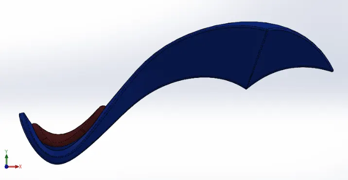
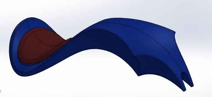
Features used
- Sketch
- Swept surface
- Lofted surface
- Trim surfaces
- Projected curves
- Boundary surface
- Mirror
- Fill surface
- Surface knit
- Split line
- Extruded surface
- Fillet
- Swept cut
- Shell
Extruded surface
This feature extrudes a sketch or sketch contours in one or two directions to create a surface feature. The direction, starting point of the extrude and extent can be controlled.
Lofted surface
It creates a lofted surface between two or more profiles or sketches. It requires start and end constraints and guide curve is required to control path shape.
Swept surface
This feature sweeps a closed profile along an open or closed path to create surface feature.
Fill surface
This feature patches a surface within a boundary defined by edges, sketches, or curves.
Knit surface
This feature combines two or more adjacent, non-intersecting surfaces into a single surface body
Assembly
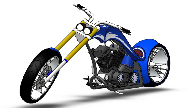
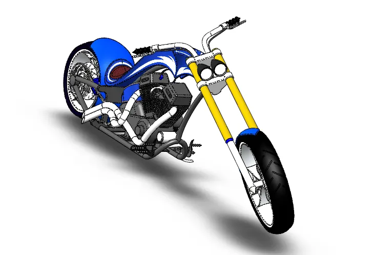
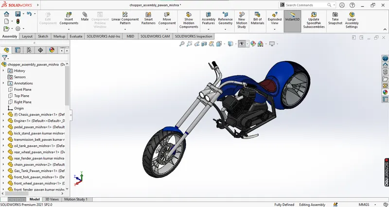
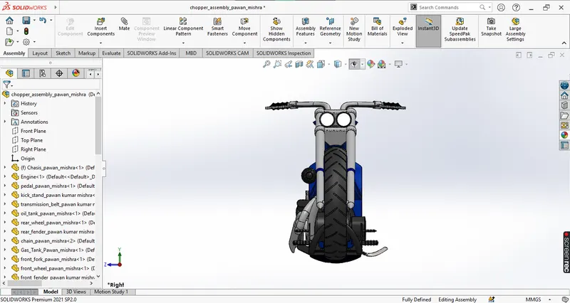
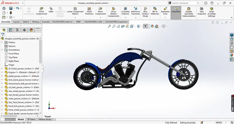
The parts were inserted into the assembly environment and assembled using appropriate mates.
Mates
Mates are used to create geometric constraints between assembly parts, we can define the linear and rotational movements of the components. We can move a component within its degrees of freedom, visualizing the assembly's behavior. For example coincident, parallel, concentric, etc.
-
Rendering
Rendering or image synthesis is the process of generating a photorealistic or non-photorealistic image from a 2D or 3D model by means of a computer program.
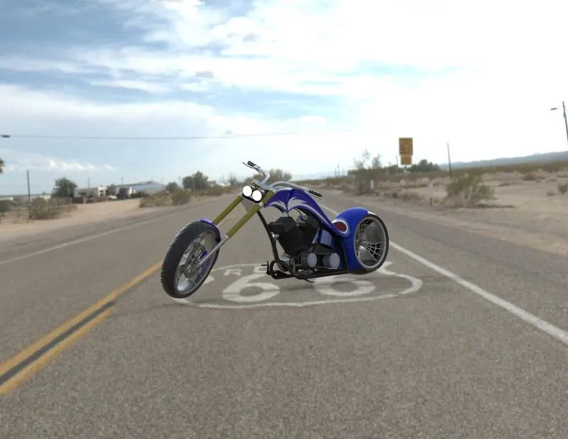
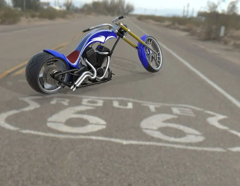
In this project the rendering is done with photoview 360 and solidworks visualize. The decals were added to the models like gas tank, rear fender to give them better look.
PhotoView 360
This is a SOLIDWORKS add-in that produces photo-realistic renderings of SOLIDWORKS models. The rendered image incorporates the appearances, lighting, scene, and decals included with the model.
Solidworks visualize
It is used to create photo-quality content in the fastest and easiest way. We can–from images to animations, interactive web content, and immersive Virtual Reality. Bring our products to life
Rendered images
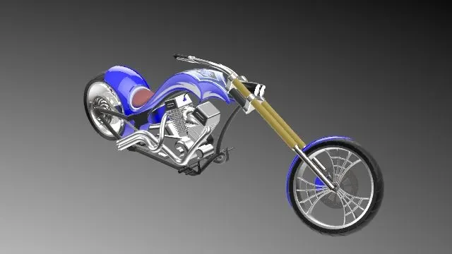
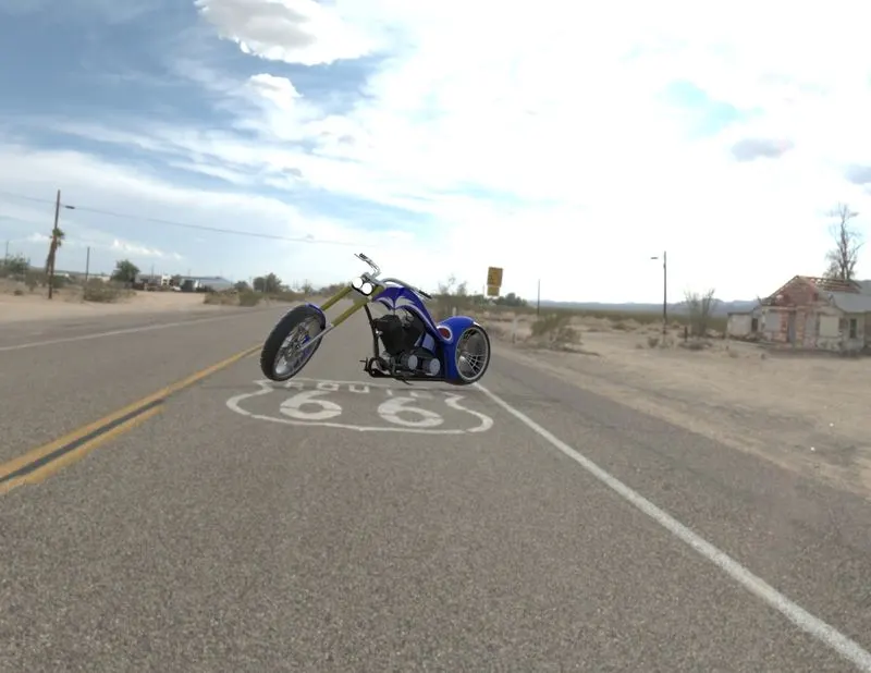
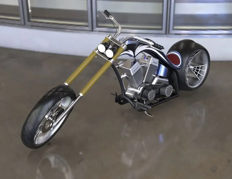
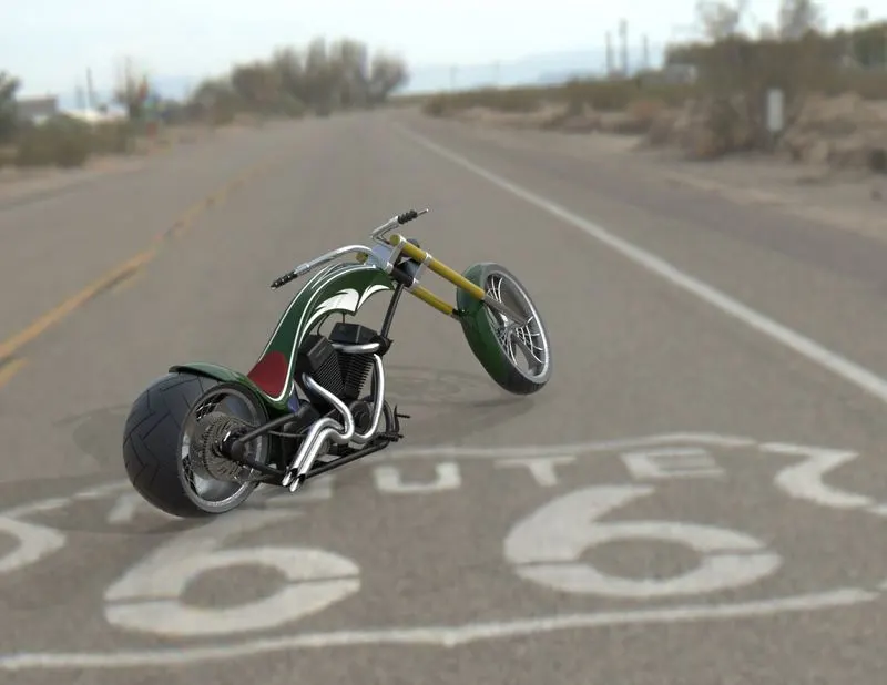
-
Conclusion
The chopper parts were modeled individually with fully constrained sketches and the parts were inserted into the assembly environment and chopper was assembled using the appropriate mates. Then the decals were added to the models like gas tank, rear fender to give them better look. Then the photo realistic render was created using the solidworks visualize and photoview 360. Thus a good understanding of solidworks tools and features was achieved.