Design of Boiler Tubes and Assembly for Petrochemical Plant
Design and assembly of Boiler tubes for petrochemical plant
Abstract
The aim of this project is to design and assemble a boiler for a petrochemical plant. The boiler consists of a fuel oil fired burner and its capacity is to produce 8TPH of
steam. The Boiler must be designed with proper material selection and mathematical calculation to avoid explosions that can cause severe damage to life and property.
The modern day boiler shell is made up of IS 2002, alloy steel, the fire tubes are made up of XID tubes conforming to SA-178A specifications is used to maximize the heat
transfer which would result in increased efficiency. The IS 2002 alloy is also used to fabricate the combustion chamber, return chamber, tube sheet and the furnace. The
three pass configuration is used for making the best use of the heating surface area to improve the overall efficiency. The boiler is considered to be operated at pressure
of 1MPa and temperature of 111.40 C to produce the dry saturated steam.The boiler is also fitted with accessories and mountings to provide safe and efficient operation of
the boiler. The boiler is supplied with good quality feed water have very little impurities. The parts were modeled and assembled in NX-CAD software.
Introduction
Boiler
A boiler is a closed vessel in which water is heated and converted into steam. The vaporized fluid formed exits the boiler for use in various processes or heating
applications like water heating, Central heating, chemical industries and sugar processing industries. Since the boiler is used to produce steam so it is also referred as a
steam generator .The fuels like wood, coal, fuel oil, or natural gas are used as a fuel for boiler combustion. Electric steam boilers use resistance or immersion type heating
elements. There is the efficiency of boiler ranges from 80% to 88%. The typical losses occurring in the boiler are incomplete combustion, radiation losses from the shell
etc. The materials used for boiler construction are IS 2002, alloy steel, stainless steel, ferritic stainless steel, Copper, cast iron for domestic use boiler.
Boiler classification according to pressure
- High pressure boiler - Boilers operating over 15 PSI.
- Low pressure boiler - Boiler operating below 15 PSI.
Boiler in petrochemical industry
The Petrochemical Industry is based on hydrocarbons derived from fossil fuel resources and biomass. The processes within this industry provide intermediate materials
that serve as a basis for the manufacture of many everyday objects. The types of Boiler used in petrochemical industries are Water tube boiler, Fire tube boiler and Steam
superheated Boiler. The fire tube boiler is used due to its compactness and simplicity in design. Since it operates at low pressure the chances and risk of explosion is vey is
less, hence it can be preferred over water tube boiler.
Types of Boiler
- Water tube boiler
- Fire tube boiler.
Water tube boiler
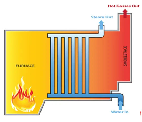
In water tube boiler the combustion takes place in large combustion chamber which is surrounded by water which gets converted into steam. It has operating principles
opposite to the fire tube boiler.
A Schematic of Water tube boiler
Types of Water Tube Boilers
- Horizontal Straight Tube Boiler.
- Bent Tube Boiler.
- Cyclone Fired Boiler.
Horizontal Straight Tube Boiler
It can be subdivided into two different types,
- Longitudinal Drum Water Tube Boiler.
- Cross Drum Water Tube Boiler.
Bent Tube Boiler
It can be sub divided into four different types,
- Two Drum Bent Tube Boiler.
- Three Drum Bent Tube Boiler.
- Low Head Three Drum Bent Tube Boiler.
- Four Drum Bent Tube Boiler.
Advantages of Water Tube Boiler
- It is high capacity thermal power plants.
- Due to convectional flow, movement of water is much faster than that of fire tube boiler; hence rate of heat transfer is high which results into higher efficiency.
- Very high pressure in order of 140 kg/cm2 can be obtained.
- High steam flow rate boilers can be made.
Disadvantages of Water Tube Boiler
- The water tube boiler is not compact in construction.
- It requires a large floor area.
- It is costly to manufacture and install.
- Large Size makes it difficult for transportation and construction.
Fire tube boiler
Fire tube boilers, also called as smoke tube boilers, are one of the most commonly used industrial boilers. It is most suitable for petrochemical plant application because
they can better cope with sudden high demand and fluctuations in steam requirements.
Combustion takes place in the furnace and the exhaust gasses (flue-gasses) passing through a series of tubes before they exit through a chimney. Because the exhaust
gasses pass through tubes submerged in water, the boiler is called as a fire/smoke tube boiler. Water tube boilers have tubes full of water that are surrounded by exhaust
gas i.e. the opposite of a fire tube boiler configuration. The fire tube can be made in (1, 2, 3, 4, passes) based on the application. The number of passes is increased to
increase the heat transfer area and hence the efficiency of the boiler. The water and steam both are in same vessel in a fire tube boiler. Hence the steam production is
limited to maximum 17.5 kg/cm2 and with a capacity 25 TPH of steam.
Cross Sectional view of 3 pass Fire tube boiler with wetback design.

Fire Tube Boiler Design types based on rear wall design
Wet back Fire tube boiler
In this type of a boiler design the boiler has water surrounding the rear end of the tubes. The separate tube sheets are used at the front and rear end so they can expand
and contract independently in response to the temperature changes between the passes. The lift off or special hinged doors are used that require no cool down period and
can be opened immediately for maintenance and service. It also reduces the required floor space area for a certain application. The frequent maintenance of the boiler is
not necessary. It has higher initial cost but it has long term fuel savings since it more efficient.
Dry back
In this type of boiler design the rear wall is made of metal lined with the refractory lining and bricks. The common tube sheet is used which caused extreme thermal stress
in response to temperature differentials. It uses a heavy door which requires more space to open it and also has larger cool down period. It requires large floor area for
operation and opening of the door. The regular periodic maintenance of the refractory is required. It requires less initial investment and has ease of serviceability.
Types of Fire Tube Boiler
There are two different types of fire tube boiler
- External furnace fire tube boiler.
- Internal furnace fire tube boiler.
Few other types
- Velcon boiler
- Scotch marine boiler.
- Cornish boiler.
- Cochran boiler
- Simple vertical boiler
- Locomotive boiler
- Lancashire boiler
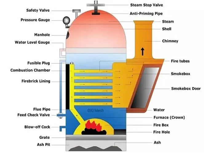
Cochran Boiler
It is a type of internally fired fire tube boiler. It is majorly used in low pressure, and vertical drum air boiler. These boilers are not best for high-pressure steam
applications due to its construction. The Cochran boiler is a portable boiler. It can be easily shifted from one place to another. It is a modified version of the simple vertical
boiler.
A schematic of Cochran Boiler
Advantages
It is a portable boiler and so the transfer and reinstallation of the boiler is easy.
Applications
This type of fire tube boiler can only use oil or coal fuel for producing hot gases. The Cochran boiler is best for small industries and power plants.
Cornish Boiler
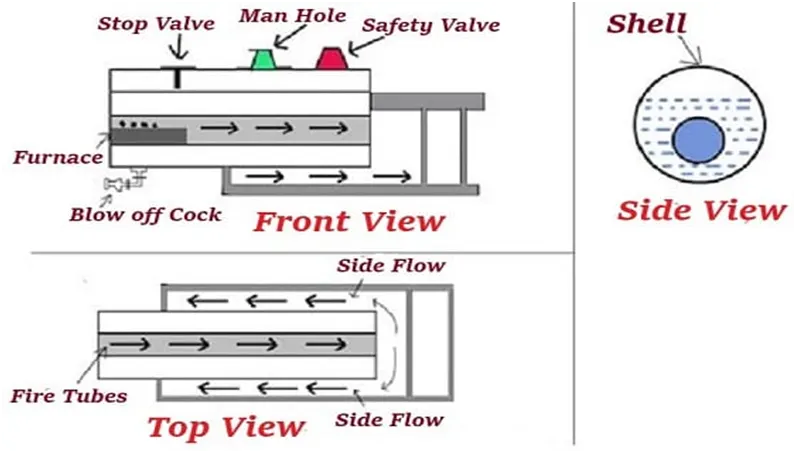
The Cornish boiler can produce steam pressure up to 20 bar and can have steam generation rate of 6.5 TPH. It can also be easily relocated and reinstalled. It is an
example of single pass fire tube boiler. The common dimension ranges from 4-7m in length, 1.2-1.8m in diameter. These boilers also use to run steam turbines.
A schematic of Cornish Boiler
Advantages
- It has a very simple design.
- Low maintenance and cost, easy construction, and is portable.
Application
Chemical industry, sugar mills, and small hydropower plants.
Locomotive Boiler
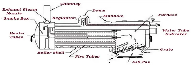
A locomotive boiler is a portable boiler. It was used in the railway engines up to the 20th century. It is an example of externally fired boiler. This boiler has a horizontal axis
drum arrangement, large furnace area, and multiple fire tubes. The major parts of the boiler are furnace, ash pit, feed pump, grate, smoke box, chimney, and fire tubes.
The grate is used to store solid coal, and the ash pit is used to collect the ash of the burnt fuel.
A schematic of locomotive boiler
Applications
Portable steam engines, locomotive(railways) engines.
Advantage
The locomotive boiler is that it has a high rate of steam generation.
Disadvantage
It has low overall efficiency.
Horizontal fire tube boiler
This type of fire tube boiler is used in thermal power plant of low capacity. It consists of a horizontal shell (drum) into which numbers of horizontal tubes (fire tubes) and
the furnace is assembled. These fire tubes are submerged in water. The suitable fuel is burnt in the furnace and the combustible gasses move to the rear from where they
enter into fire tubes and travel towards the front into the smoke box.
A schematic of Horizontal fire tube boiler
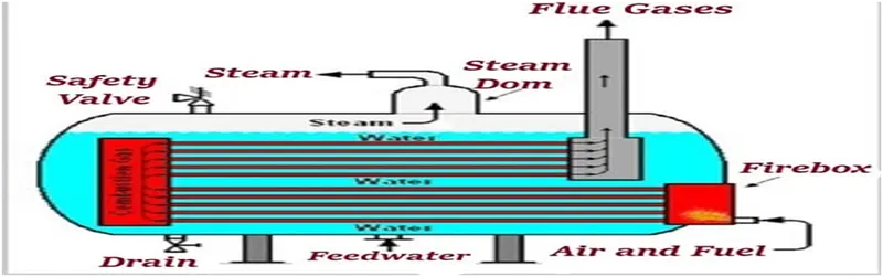
During this travel of gasses in tubes, they transfer their heat into the water and steam is generated. As steam is produced, the pressure of the boiler increases.
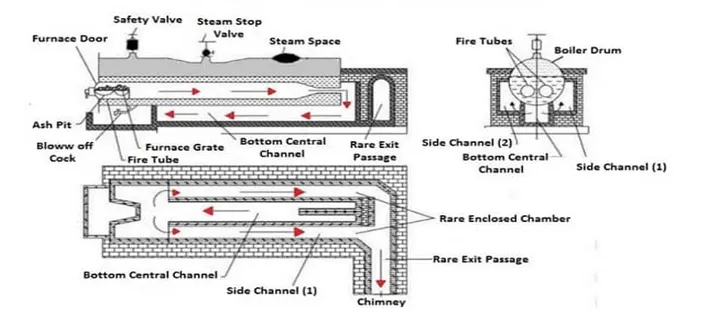
Lancashire Boiler
The Lancashire boiler is a type of internally fired natural circulation boiler. This boiler has a furnace inside the boiler. The steam generated is collected at the top. The boiler
is fitted with the mountings for safe operation.
A schematic of Lancashire Boiler
Advantages
- High thermal efficiency (from 80% to 90%).
- It has high working pressure up to 16 bar.
- It has low fuel consumption as it has a natural circulation of steam.
Application
Tire industries, sugar industries, textile industries, and paper industries.
Boiler fuel- Fuel oil
It is a fuel used in stationary boiler installations, on oceangoing and river ships, and in industrial furnaces of various types. Boiler fuel oils are classified based on their raw
materials such as petroleum oils, which are produced from petroleum residue, shale oils and coal oils, which are heavy fractions of tars from semi-coking of coal. The fuel
oils are distinguished according to their viscosity, sulfur content, ash content, solidification temperature and heat of combustion. Petroleum oils which have low sulfur
content (0.5%), sulfurous (2%), high sulfur (3.5%) accounting for majority of fuel oils.
Advantages of Fire Tube Boiler
- Designing of the boiler is simple and maintenance cost is less.
- It is quite compact in construction.
- Fluctuation of steam demand can be met easily.
- It is also quite cheap.
- Treatment of the feed water is not much essential.
- Fewer experts are required for operation.
- This boiler has lower risk of explosion.
Disadvantages of Fire tube Boiler
- As the water required for operation of the boiler is quite large, it requires a long time for rising steam at desired pressure.
- As the water and steam are in the same vessel the very high pressure (limited to 20 bar) of steam is not possible.
- The steam received from the fire tube boiler is not very dry.
- The thermal efficiency of fire tube boiler is about 70% which is less compared to water tube boiler.
- The fluctuation in load is difficult to manage.
Applications
- The fire tube boilers are best suited for small scale industries.
- They are used in railways
- It is used in marine, hydroelectric and petrochemical plant.
Horizontal fire tube boiler- Parts and their function
Shell
The shell serves as a pressure vessel in which the parts like combustion chamber, furnace, and fire tubes are assembled. The shell is filled with water with space at the top
for steam generation.
Tubes
Tubes pass from one end of the shell to the other carrying the flue gases it could be done in single, or multiple passes. The shell and tubes are installed mostly
in horizontal orientation, and the vertical orientation is very less in use.
Furnace
The furnace is the place where combustion occurs in the boiler and it is the hottest part of the boiler. Corrugated furnaces can be used to increase the mechanical strength
and heating surface of the furnace, but it has a high manufacturing cost. Hence a simple furnace is mostly used. The furnace is generally made of mild steel and burner
located outside the boiler vessel is connected by means of a flange coupling.
Tube Sheets
Tube sheets are provided at both the ends of the shell. They provide sealing and mounting holes for the tubes.
Feed Pump
A feed pump is used to force the feed water at high pressure into the boiler. The commonly used pumps are,
- Reciprocating pumps
- Rotary pumps
The reciprocating pumps are driven directly by coupling them to the steam engine. The rotary pumps are driven by the steam turbines or by electric motors.
Burner
Fuel, air and ignition source are required for combustion. Fuel and air is fed into the furnace by the burner where the air and fuel are mixed, ignited and burnt. the source
of ignition is provided by an igniter. The igniter is an electrode that produces an electrical arc, similar to a spark plug, but it is larger in size. The typically used fuels
include light fuel oil (LFO), methane gas, coal etc. The burner is generally mounted at the front.
Reversal Chamber
Reversal chambers are used to change the direction of the exhaust gasses as they exit from one pass and are directed into another. Reversal chambers located away from
the burner are called as 'rear reversal chamber and the one closer to the burner is called as 'front reversal chamber.
Smoke box
The smoke box is the final part of the boiler that the exhaust gas passes through before exiting to the chimney.
Natural Circulation Boiler
The circulation of the boiler happens due to the convection currents which are developed when he water is heated. The circulation also happens due to the density
difference when the water in the boiler is heated.
Design Considerations for a boiler
Function
The main function of boiler is to generate steam. So the design intent should be to increase the heat transfer. The type of steam required varies according to the
application. The Boiler must be designed with proper material selection, conformance to standards, analysis and installed, operated carefully to avoid explosions that can
cause severe damage to life and property.
Parameters
- Capacity/steam output required, usually measured in ton per hour (TPH) or kg/s.
- A boiler is expected to have a heating surface of about 5 square feet per brake horsepower.
- Maximum Production quantity of steam with minimal fuel consumption.
- Feasibility of installation and required floor space.
- Manufacturing Considerations.
- Minimal operator attention should be required during operation.
- Capable of quick starting.
- Conformity to safety regulations.
- Tensile strength of material must be enough to sustain the temperature and pressure.
- The good quality of feed water should be used. The hardness or softness the feed water can also be used determine the material of the boiler.
- Heat source is commonly got by burning the fuels like Coal, Diesel, Wood etc. so the fuel which is used its properties must be carefully studied.
- Steam condition - pressure, temperature, enthalpy etc.
- Safety and Environmental considerations.
- Cost of the boiler.
Boiler Accessories and Mountings
Boiler mountings
These are mechanical devices that are essential for the smooth and safe operation of the boiler, which are usually mounted on surfaces of the boilers. Mountings are water
level indicator, safety valve, pressure gauge, etc. The boiler cannot function safely without the mountings.
A schematic showing mountings used in a boiler
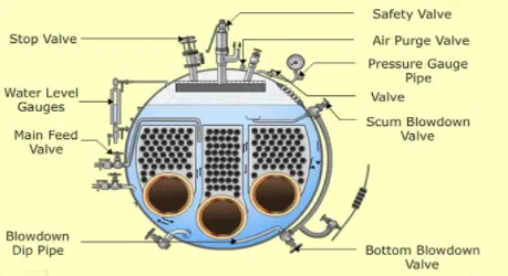
Boiler Mountings
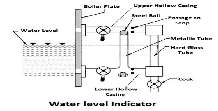
Water Level Indicator
It is one of the main fitting in the boiler; it indicates the water level inside the boiler. It is a safety device upon which safe working of the boiler depends.
Working Principle
Water-tube indicator the water consists of a vertical hard glass tube G which is fitted with two gunmetal tubes A and B. The tube A connects the steam space of the boiler with the glass tube and the tube B connects the water space of the boiler with the glass tube.
The tube A is provided with a valve ‘S’, called a steam valve, and tube B is fitted with another valve ‘W’, called a water valve. In addition to these valves, a third valveD, called drain valve, is fitted to the water level indicator through which water together with condensed steam from the gunmetal tube A is drained from time to time.
Pressure Gauge
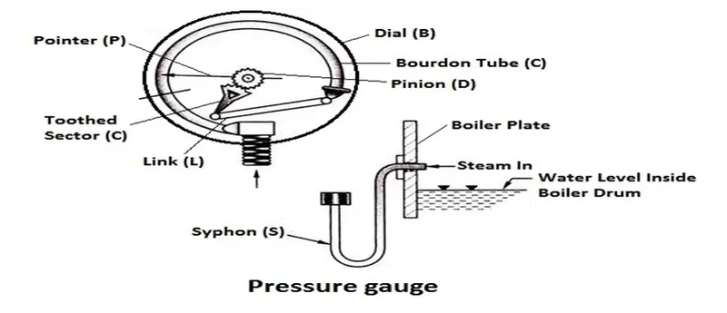
Pressure gauges are used to measure the pressure of steam inside a steam boiler. The pressure gauge is fixed in front of a steam boiler.
Working Principle
The pressure gauge shown in fig is bourdon pressure gauge. It consists of a circular spring tube A. One end of the bourdon tube is closed and connected to a link L and
the other end is sequared to a Hollow block B. The link L connects the closed end of the tube to the toothed sector C which is hinged at O. The toothed sector gears with
pinion D which carries a pointer P. The pointer moves on a dial graduated in pressure units.
Safety valves
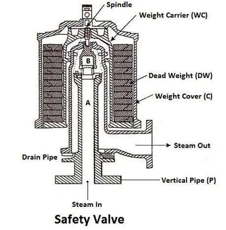
These are the devices attached in the steam boiler for preventing explosions due to excessive internal pressure of steam.The safety valve is an instrument which prevents
the boiler pressure from rising above its normal working pressure by automatically opening when the boiler pressure exceeds the normal working pressure, Thus allowing
excess steam to escape into the atmosphere until the pressure comes down to its normal valve. Thus, a safety valve ensures safety to a boiler from being damaged due to
excessive steam pressure.
The safety valves commonly used are:
- Deadweight safety valve.
- Lever safety valve.
- Spring-loaded safety valve.
Steam Stop Valve
The function of a stop valve is to control the flow of the steam from within the boiler and to stop it completely when required. A stop valve or junction valve is used to
regulate the flow of steam from the boiler.
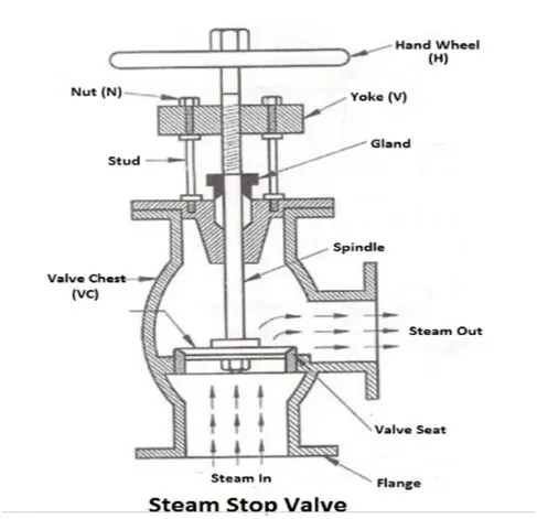
The valves mounted on the boilers, which change the direction of flow of steam by 90° are called junction valves, while valves fitted in pipelines which allowing the steam
in the same direction are called stop valve.
Blow-off Valve
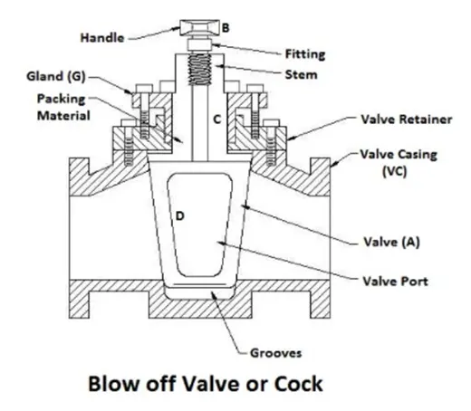
The function of a blow-off valve is to remove periodically the sediments deposited at the bottom of the boiler while the boiler is in operation and to empty the boiler while
it is being cleaned or inspected.When the blow-off valve is opened the water which is under the pressure of steam, rushes out with tremendous velocity thus carrying out
the sediments along with it.
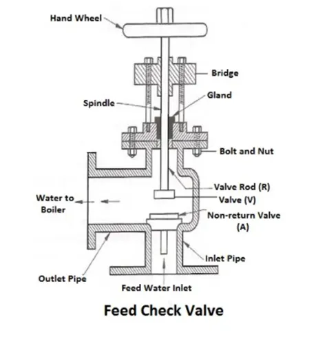
Feed Check Valve
When the level of water in the boiler falls, it is brought back to the specified level by supplying the additional water called feed water. The pressure inside the boiler will be
high therefore the pressure of the feed water has to be raised by a pump before it is fed into the boiler. The feed water under high pressure is fed into the boiler through
the feed check valve.The function of a feed check valve is to control the flow of water from the feed pump to the boiler and to prevent the backflow of water from the
boiler to the pump when the pump pressure is less than the pressure or when the feed pump ceases to work. Evidently feed check valve is placed at the boiler end of the
delivery pipe of the feed pump.
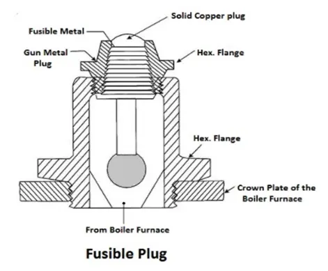
Fusible Plug
The plug is made up of tin or leads alloy, which has a low melting point. The function of the fusible plug is to put-off the fire in the furnace of the boiler when the water
level falls below an unsafe level and thus avoids the explosion, which may take place due to overheating of the tubes and the shell. It is fitted over the crown of the
furnace or the combustion chamber.
Non-Return valve
The non-return valve is also called as stop or check valve. It main function is to allow the flow of steam in only one direction and also prevent the backflow of the fluid.
Natural Draught
Draught is defined as the pressure difference which causes a flow of air or gases from one point to another point in the boiler system.
- To supply sufficient air for complete the combustion in the furnace.
- To remove flue gases from the system after combustion
- To facilitate the proper heat exchange in the boiler.
Boiler accessories
These are the devices that are installed with boilers to improve the operating condition and overall efficiency of the boiler plant. The boiler accessories are the devices,
which form an integral part of a boiler but are not mounted on it. They include super heater, economizer, feed pump etc
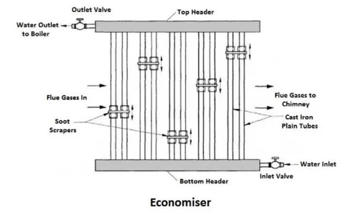
Economizer
The combustion gases coming out of the boiler contain a large quantity of heat. Therefore the maximum amount of heat from the gases should be recovered before it
escapes to the chimney. In the economizer, heating the feed water does the recovery of heat in the flue gases. The economizer is placed in the path of the gases. They
improve the overall efficiency of the boiler by reducing fuel consumption.
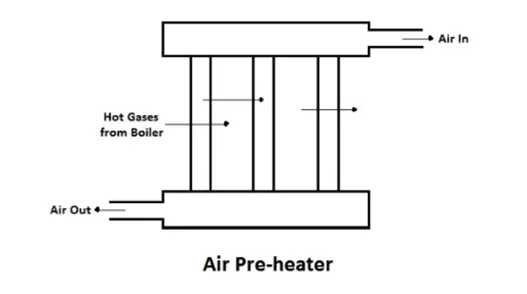
Air Pre-heater
The air preheater is an accessory that recovers the heat in the exhaust gas by heating the air supplied to the furnace of the boiler. Supplying preheated air into the
furnace produces a high furnace temperature and accelerates the combustion of the fuel. Thus the thermal efficiency of the plant will be increased.
Advantages
- Increase in the steam generation rate.
- Better combustion with less soot, smoke and ash, and
- Low-grade fuels can be used.
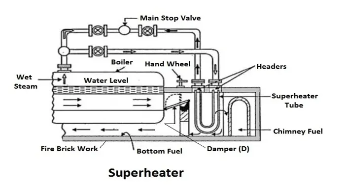
Super heater
The super heater is used in boilers to increase the temperature of the steam above the saturation temperature.The dry saturated steam generated in the boiler is passed
through a set of tubes placed in the path of the flue gases, in which it will be heated further by the hot gas to increase its temperature about the saturation temperature.
Manufacturing processes involved
Manufacturing of boiler involves a variety of skill and unique manufacturing methods. It requires facilities for metal removing, forming, casting, joining of metal by
welding, heat treatment, different destructive and non-destructive testing.
Boiler Tube Manufacturing
Boiler tubes are seamless tubes and are made of either carbon steel or alloy steel. They are widely used in steam boilers, for power generation, in fossil fuel plants,
industrial processing plants, electric power plants, etc. Boiler tubes can transmit medium-pressure boiler fluid or high-pressure boiler based on the application. They are
available in variety of diameter, thickness and material. Boiler tubes are made seamless to avoid any leakage and improve its strength.
Heat treatment
After the tube is manufactured the heating and cooling of the high-pressure boiler pipes increases toughness, hardness and wear resistance.
Types of Heat Treatment
Quenching
It is done to increase the hardness of the high-pressure boiler tube. The pipe is heated evenly to an appropriate temperature and then quickly immersed into water or oil
for instant cooling. This is followed by cooling in air or in the freezing zone.
Tempering
It is used to remove brittleness from the pipe. Since quenching can make the pipe brittle due to the air entrapped.
Annealing
After tempering to remove the internal stress developed in the pipe annealing is used. In this process, the seamless tube is heated to the critical temperature and then left
for slow cooling in ash or lime.
Boiler Tube maintenance/ Rust removal
- A solvent and emulsion mixture is used for basic cleaning this can remove only dust, oil, etc.
- The second method of rust removal is using manual or power tools. This method of cleaning can get rid of oxide coatings, welding slag and rust.
- Through chemical and electrolytic methods, also known as acid cleaning rust can be removed very effectively.
- Spray rust removal is one of the best method for cleaning of the boiler tube as it can remove dirt, oxide and rust more effectively.
Forming process
Roll forming is a continuous metal forming process in which sheet is bent or formed it to a continuous cross section. The process is done between successive pairs of rolls
that change the shape until the desired section is completed. For large sheets hydraulic presses are used.
Advantages
- The roll forming process allows operations such as punching, notching, and welding to be performed in-line.
- Roll form tooling allows for a high degree of flexibility.
- Roll forming can provide better dimensional control.
- Repeatability is inherent in the process so it minimizes the problems due to tolerance build up.
- Roll forming is a high speed process and gives a good surface finish
Submerged arc welding
In this type of welding the weld and arc zone are submerged beneath a blanket of flux. The flux material becomes conductive when it is molten, creating a path for the
current to pass between the electrode and the work piece.
Advantages
- Strong, sound welds are readily made.
- Minimal welding fume is emitted.
- Minimal arc light is emitted.
- SAW is suitable for both indoor and outdoor works.
- Less distortion.
- Deep weld penetration.
- Minimal edge preparation.
- High deposition rates are possible.
Plasma cutting
Plasma cutting (plasma arc cutting) is a melting process in which a jet of ionized gas at temperatures above 20,000°C is used to melt and expel material from the cut.
This heat melts the metal and the gas flow ejects it from the cut. Plasma gases are usually argon, argon/hydrogen or nitrogen. This process is used to cut the tubes and
the sheets with good accuracy.
Drilling and laser cutting
It is used to produce holes with tighter tolerances
XID-Tubes
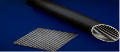
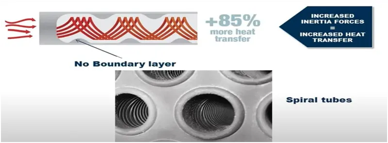
X-ID tubes are internally augmented tubes that significantly increase the heat transfer for gas flowing inside the tube. Helical ribs are embossed on the inside of the tube
to provide a increased surface area. This improves heat transfer compared to a plain tube. Cost savings of up to 20% on the entire boiler package can be obtained with X
ID tubes. X-ID tubes have been used in boilers ranging from 60 HP to 2200 HP.
X-ID TUBING BENEFITS:
- Achieves 85% higher tube side heat transfer.
- Reduces fuel consumption.
- Reduces footprint and overall space requirements.
- Increases boiler efficiency, lowers emissions of NOx and other pollutants.
- Results in up to a 20% cost savings over bare tube designs.
X-ID tubes manufacturing
It is produced by first embossing the rib pattern on the unrolled strip of metal, which is then rolled and welded into a tube in an ERW mill. The height of the rib is over and
above the wall thickness, so the combined depth of the tubing wall and ribbing is over and above minimum wall specifications. X-ID tubes meet ASME standards for all
material, dimensional and testing (destructive and non -destructive) requirements set forth in SA-178A specifications.
Heat flow in spiral tube
The heat flow in a typical boiler tube
Materials Used in the boiler
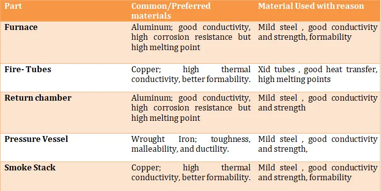
Heat Transfer in Fire Tube Boiler
Fire-tube heat transfer Path
- Furnace to the return chamber.
- Return chamber to 2nd pass tubes.
- 2nd pass tubes to smoke box.
There are three modes of heat transfer
Conduction
Conduction is defined as transfer of heat from one body to another body in physical contact with each other. The heat is transferred through a solid material from hotter
part of the body to the colder part. There is no movement of molecules due to lattice vibration or flow of free electrons. In the boiler the conduction occurs when the heat
is received by the metal heating surface.
Convection
Convection is defined as transfer of heat through liquid or gases from region of higher temperature to lower temperature.
Radiation
Radiation is defined as the heat transfer through electromagnetic waves. It requires no medium for heat transfer.
Heat Transfer inside a Fire Tube Boiler
- Transfer by radiation and convection between the combustion gases and wall tubes.
- Conduction through wall tubes to water
- Transfer by convection from tubes to liquid-water vapor mixture in the different passes.
Calculations and Specifications
Specifications
Boiler Capacity - 8TPH (8000kg/hr)
Number of passes - 3 Pass
Type of boiler - Fuel oil
Operating Pressure - 10kg/cm2 (10 bar or 1 Mpa)
Fuel Consumed Per hr - 0.54 TPH
Gross calorific value of fuel - 10200 Kcal/Kg
Furnace Temperature - 12000C to 1600o C
Mass Flow rate of steam
m. = 8000 kg/3600 s
m= 2.22 kg/s
Boiler Heat Rate (BHR)
It is defined as the amount of heat required to produce the 1 kg of steam at desired temperature or pressure.
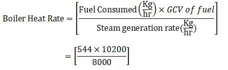
BHR = 693.6 Kcal/Kg
Fuel Consumption- Per Hour
https://www.thermodyneboilers.com/wp-content/uploads/2016/07/Thermodyne-Boiler-Bible.pdf
From Pgno: 68
Boiler Efficiency = 82%
Fuel Calorific Value = 10200 Kcal/Kg
Fuel Consumption for 1 TPH = 68 kg/hr
Fuel Consumption for 8 TPH = 544 kg/hr
Operating Temperature Calculation
From (Saturated water- Pressure Table)
The Tsat at 1MPa = 179.88℃
Saturated liquid specific volume (From Table) = 0.001127 m3 /kg
Saturated vapor specific Volume (From Table) = 0.19436 m3 /kg 3.
Third Pass temperature T3
T3= 180℃ + 100℃
T3 =280℃.
Second Pass temperature T2
T2 = 𝐹𝑢𝑟𝑛𝑎𝑐𝑒 𝑡𝑒𝑚𝑝𝑒𝑟𝑎𝑡𝑢𝑟𝑒+𝑇ℎ𝑖𝑟𝑑 𝑝𝑎𝑠𝑠 𝑡𝑒𝑚𝑝𝑒𝑟𝑎𝑡𝑢𝑟𝑒/2
= 1200+280/2
T2= 740℃
Air temperature at 2nd Pass
Tair 2 = 𝐹𝑢𝑟𝑛𝑎𝑐𝑒 𝑡𝑒𝑚𝑝𝑒𝑟𝑎𝑡𝑢𝑟𝑒+2nd 𝑃𝑎𝑠𝑠𝑇𝑒𝑚𝑝𝑒𝑟𝑎𝑡𝑢𝑟𝑒
= 1200+740/2
Tair 2 = 970o C
Air temperature at 3 rd Pass
Tair3 = 3rd 𝑃𝑎𝑠𝑠 𝑡𝑒𝑚𝑝𝑒𝑟𝑎𝑡𝑢𝑟𝑒+2nd 𝑃𝑎𝑠𝑠𝑇𝑒𝑚𝑝𝑒𝑟𝑎𝑡𝑢𝑟𝑒/2
= 280+740/2
Tair3 = 510oC
Heat input required by the boiler

From steam table pressure at 10 bar
For steam at 184o C, hsteam = 2777.14 KJ/Kg
For feed water at 30o C, hfeed water = 122.48 KJ/Kg

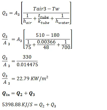
Qin = 5893.34 KJ/S
Thermal Conductivity and Heat Transfer
From the ASME Boiler and pressure vessel codes thermal conductivity is given by
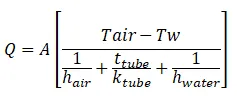
Where
Q =Heat transfer rate through tubes, KW
Tair = Temperature of air in o C.
Tw = 180℃
hwater = Thermal conductivity of air in KW/m2*
ttube = Thickness of tubes in m
ktube = thermal conductivity of carbon steel in KW/m2*K
hair = Thermal conductivity of air in KW/m2*K
A =Area of the tubes in m2
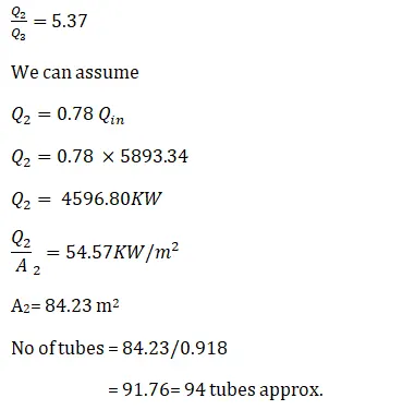
Thermal conduction in pass2
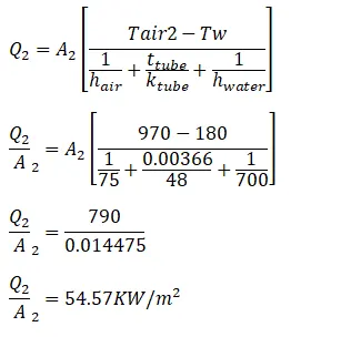
Thermal Conductivity in pass 3
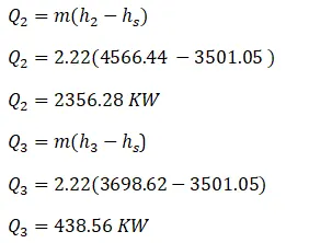
h2 steam at 970℃ & 10 bars = 4566.44 kJ/kg
h3 steam at 510℃ & 10 bars = 3698.6 kJ/kg
hs steam at 180℃ & 10 bars = 3501.05 kJ/kg
Design of the Furnace
For calculation purpose the furnace, shell and fire tubes are considered as perfect cylinders.
Formula
Volume of cylinder V = πr2h
Lateral surface area LSA = 2πrh
https://www.engineeringtoolbox.com/saturated-steam-properties-d_457.html
The furnace Dimensions
Length -4.6m
Thickness- 16mm
Diameter -1040 mm
Volume V = 3.79 m3
Lateral Surface Area = 14.8 m2
Shell Dimensions
Length = 5432 mm
Thickness = 16 mm
Diameter = 2.3 m
Volume V = 22.5 m3
Lateral Surface Area = 39.2 m2
Fire Tube Dimensions
For second pass
Length = 4600 mm
Diameter = 63.5 mm
Thickness = 3.6 mm
Volume V = 0.0146 m3
Lateral Surface Area = 0.918 m2
No of fire tubes- 92
For third pass
Length = 5400 mm
Diameter = 63.5 mm
Thickness = 3.6 mm
Volume V = 0.0173 m3
Lateral Surface Area = 1.09 m2
No of fire tubes - 84
Reversal Chamber
Length = 800 mm.
Diameter = 1708 mm
Thickness = 14 mm
Volume V = 1.82 m3
Lateral Surface Area = 4.27 m2.
Pump Power Requirement
Formula to calculate the power required by the pump
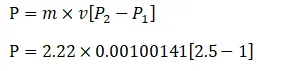
The power required by the P = 3.34 KW
Pipe Flow rate
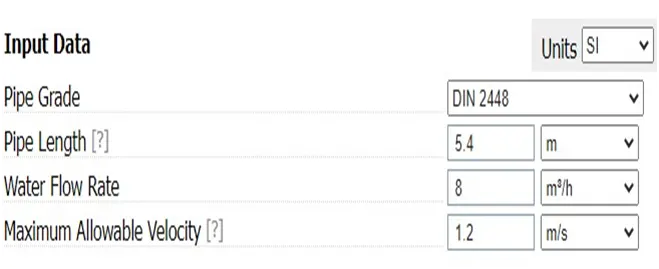
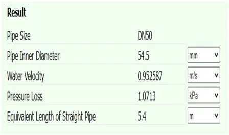
Boiler Efficiency Analysis
Effect of boiler loading on efficiency
The maximum efficiency of the boiler occurs at 2/3 of the full load capacity of the boiler, but if the load is reduced further the efficiency also decreases. If the load is
reduces further the mass flow rate of flue gases through the fire tubes also reduces and also decreases the sensible heat loss. The combustion devices require more
excess air to function effectively this increases the sensible heat loss. Hence the boiler capacity should not be lowered below 25% of its rated capacity for efficient
operation.
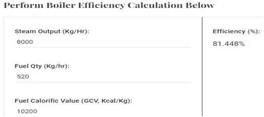
Direct Method
https://www.thermodyneboilers.com/calculators/boiler-efficiency-calculator/
Formula method
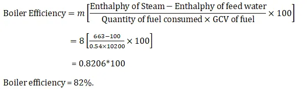
This calculation is very important for fuel consumption estimation, sizing boiler accessories, etc. The gas composition and flow rates are used for sizing pollution control
equipment like wet scrubbers, bag filters etc.
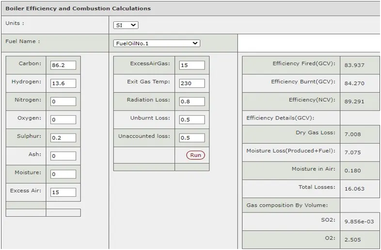

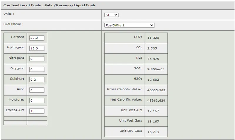
Combustion Analysis of the Fuel Oil
This shows the combustion result of the various fuel parameters like GCV, NCV, dry gas etc.
The SI units for the various parameters are
Temp-°C; Conductivity-KW/m/K; Dyn. Viscosity-Kg/M/S; Kin.Viscosity-m²/S; Sp.Heat-KJ/Kg/K; Density-Kg/m³; Pressure - MPa; Calorific Value-kj/kg.
https://firecad.net/engineering-calculations/Boiler/Combustion
Boiler Steam Data
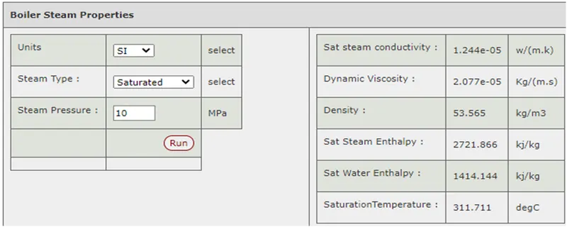
The steam properties are also available in steam tables, and are required for calculating steam side heat transfer, heat load in applications like fire tube boilers.
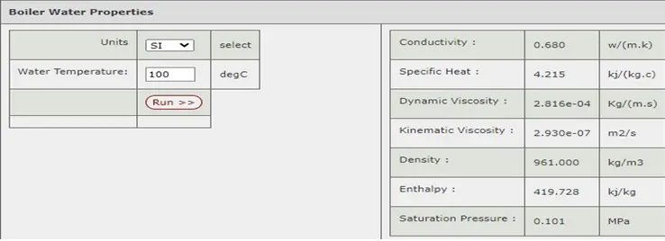
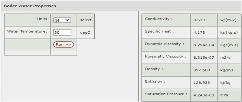
Feed Water properties
These values are also available in water tables. These value are used for sizing different equipments in the process industry and used to calculate heat transfer in boilers,
evaporators etc. The feed water at inlet should be maintained at least 82o C to remove dissolved gases mainly oxygen.
Boiler Blow down
During the steam generation process in the boiler, any dissolved solids contained in the water may remain in the boiler. Continuous operation leads to more solids
formation from the feed water, they get accumulated and reach above a certain level of concentration, where these solids start foaming and cause carryover of water into
the steam. The deposits lead to the scale formation inside the boiler, resulting in localized overheating which causes the boiler tube failure. Hence to control the level of
concentration of the solids and blowing down process is used.
Types of Blowdown
Intermittent Blowdown
The blowdown is given by manually operating a valve fitted to discharge pipe at the lowest point of boiler shell to remove the TDS, Silica and Phosphates concentration. In
intermittent blowdown. It is done by openning a large diameter line for a short period of time, the time being based on a thumb rule such once in a shift for 2 minutes. It
requires a large short-term increases in the amount of feed water fed into the boiler, and so it requires a larger feed water pumps than if continuous blow down is used. It
must be noted that a considerable amount of heat energy is lost intermittent blowdown is done.
Continuous Blowdown
There is a steady and constant dispatch of small stream of concentrated boiler water, and replacement by steady and constant inflow of feed water. This ensures constant
TDS and steam purity at given steam load. Once blow down valve is set for a given conditions, there is no need for regular operator intervention.
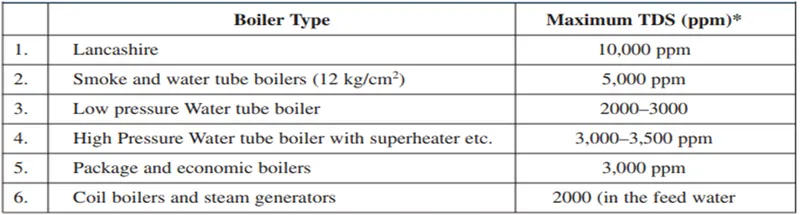
The maximum permissible limit of TDS in a boiler is around 3500 ppm
Percentage make up water - 25%
TDS in feed water - 1800 ppm
Boiler evaporation rate = 8000 kg/hr
The percentage blow down is given as

= 1800 x 25/ 8000
= 5.6%
Advantages of Blowdown
- Good boiler blow down control
- Reduced treatment and operational costs
- Less maintenance downtime
- Increased boiler life
- Lower consumption of treatment chemicals
Boiler Water Treatment
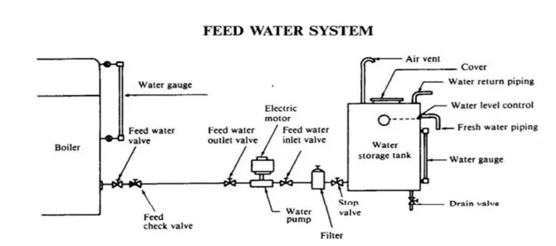
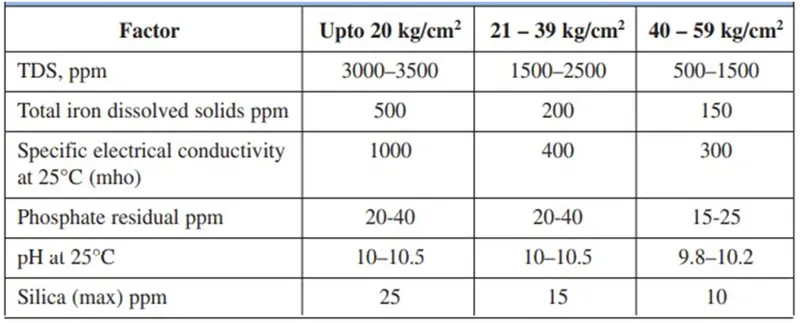
To Produce quality steam properly managed water treatment that controls water purity and TDS levels is required. A good quality feed water is required for improving the
boiler performance efficiency, and service life.When the temperatures and pressures increases the contaminents of water to behave adversely and may have damaging
effects. The soluble components come out as particulate solid, crystallized forms or as amorphous particles. When the water is boiled under pressure. But when the
solubility of a specific component in water is exceeded, scale or deposits start developing. So the external treatment processes like ion exchange, demineralization,
reverse osmosis or de-aeration can be used to remove the impurities.
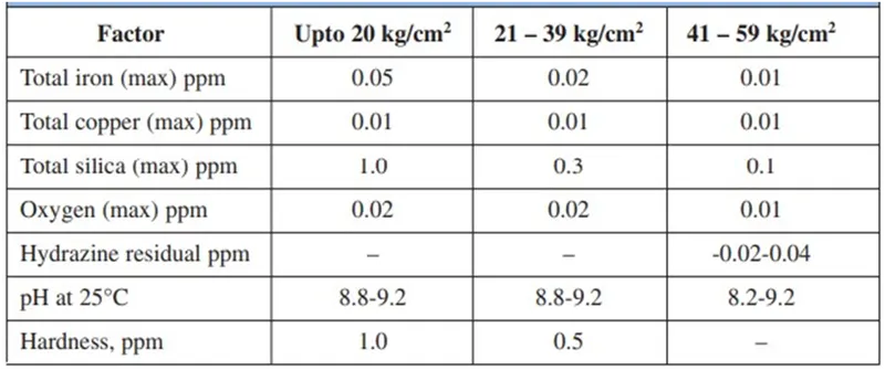
Boiler Water contaminents Limits
Feed Water ppm levels
Energy Conservation
The various energy efficiency opportunities in boiler system can be related to combustion, heat transfer, avoidable losses, high auxiliary power consumption, water quality
and blowdown. Examining the following factors can indicate if a boiler is being run to maximize its efficiency:
Stack Temperature
Stack temperature or flue gas temperature is the temperature of the combustion gases when they leave the boiler. It should be maintained be as low as possible but not
as low that the water vapor in the exhaust condenses on the stack walls. It becomes more vital in fuels containing significant sulphur content as low temperature can lead
to sulphur dew point corrosion.
Combustion Air Preheat
It is a good alternative to feed water heating to improve efficiency. In order to improve thermal efficiency by 1%, the combustion air temperature must be raised by 20
°C. The modern burners are designed to withstand higher combustion air preheat. So it can serve as an alternative to the economizer, when either space or a high feed
water return temperature make is not desirable.
Incomplete Combustion
It happens due to shortage of air or poor distribution of fuel. It is shown by change in color of smoke, and must be corrected immediately. So the proper fuel storage and
stoichiometric ratios must be maintained
Safety Standards
Even though with the advancements in the boiler technology, whenever the boiler is under operation the risk of explosion always exists due to its high pressure steam and
hot surfaces.
Common failures
Melt down.
It is caused due to the heating surface metal reaching its melting point. It occurs when the boiler is operating on very low water level. This to the boiler damage which
could result in explosion.
Thermal Shock
When the heating surfaces become overheated due to low water level and then cooler water is added the thermal shock in the drum occurs. The thermal shock can cause
excess expansion of the steam which could lead to explosion.
Steam Pressure
When the steam pressure exceeds the design pressures of the vessel there is high risk of explosion. Hence proper care must be taken to keep the steam pressure in
check.
Safety Procedures
- The appropriate water level must be maintained.
- Proper communication between the operators.
- Safety valves must be check routinely to check any malfunction.
- In case of an accident a flame guard system must stop the fuel supply to the burner.
- Proper feed water quality must be ensured, as it may lead to boiler degradation.
- During the blowdown the load of the boiler must be kept low.
- The operator must wear all the safety equipments and clothing.
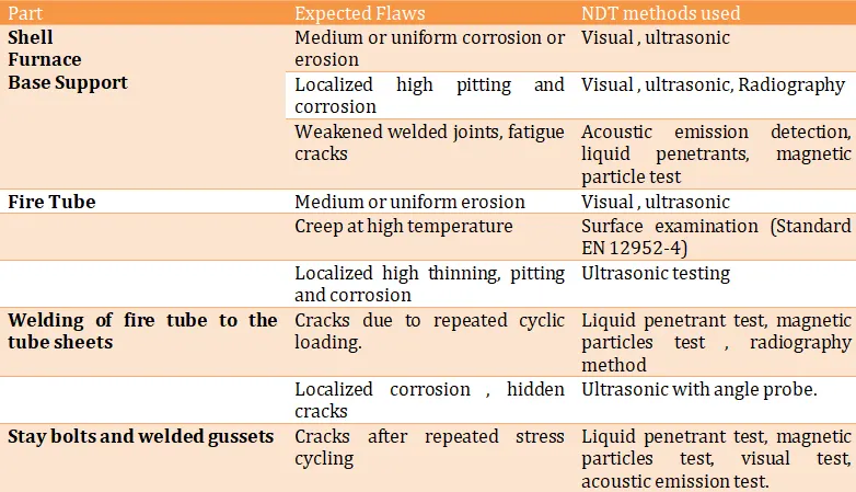
Boiler Failure Testing Methods
Cad Images
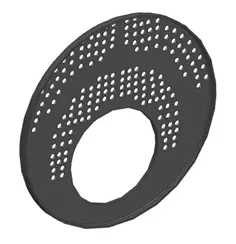
Front Tube sheet
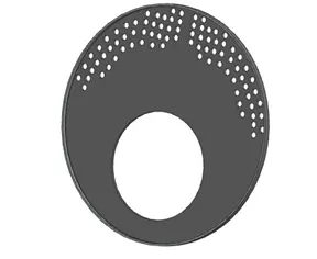
Rear Tube Sheet
Return Chamber
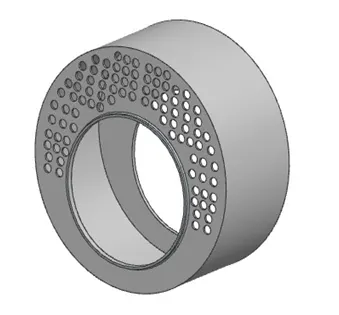
Furnace
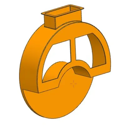
Smoke Box-Front
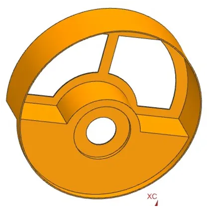
Smoke Box-Rear
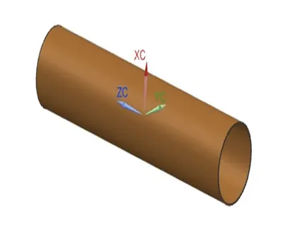
Shell
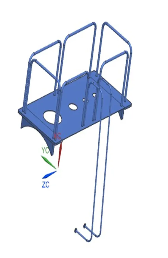
Stair Case
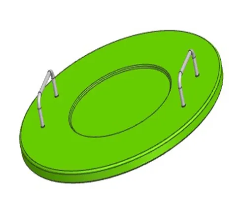
Manhole Cover
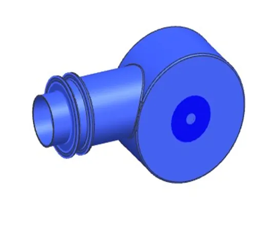
Burner
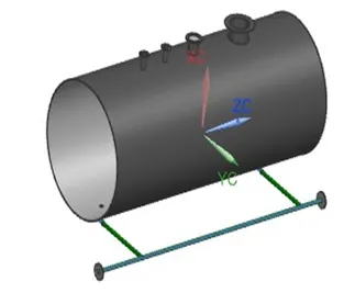
Base Support
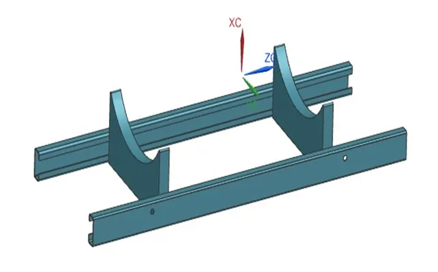
Inspection Door
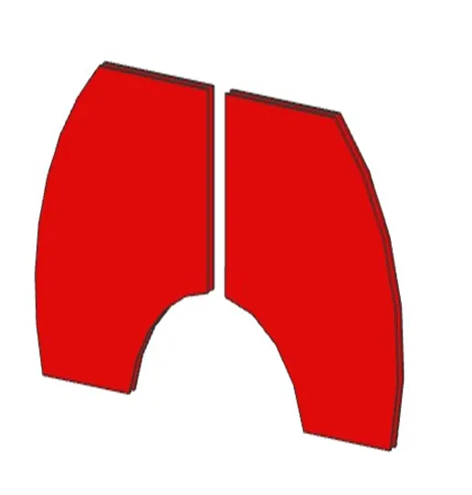
Feed Water line
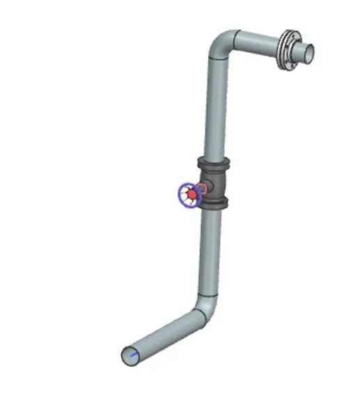
Safety Valve
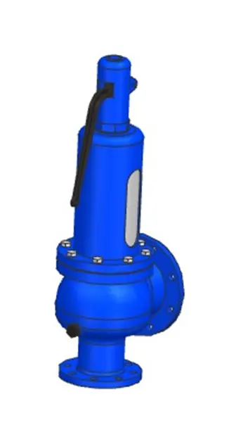
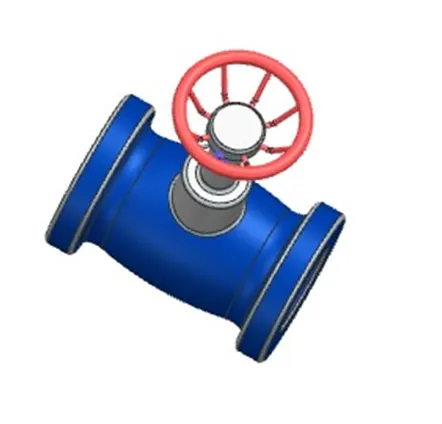
Stop valve
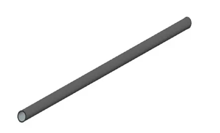
Fire Tube
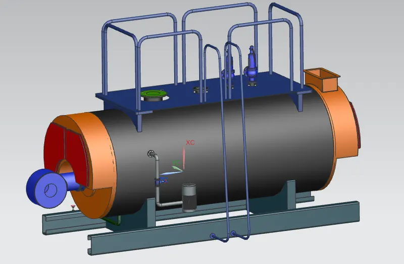
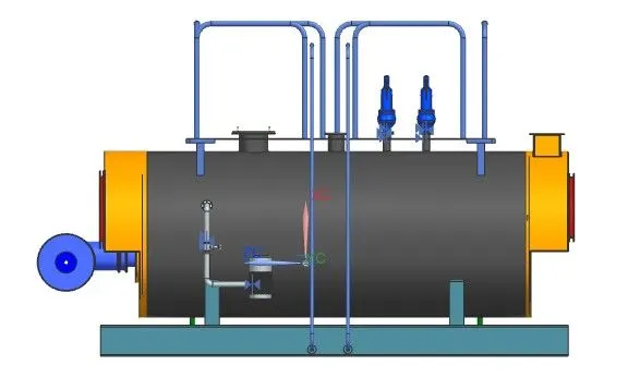
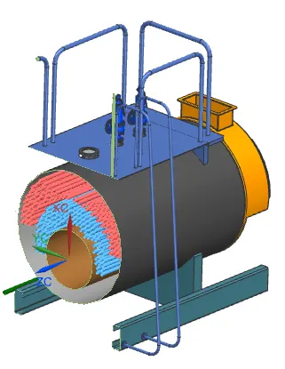
Assembly Images
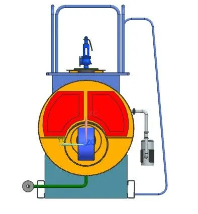
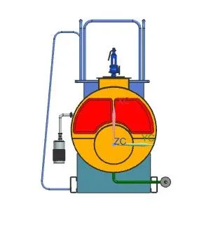
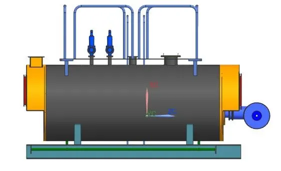
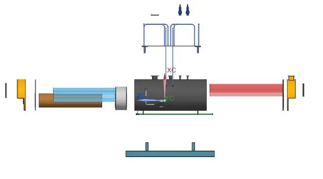
Exploded View of the assembly
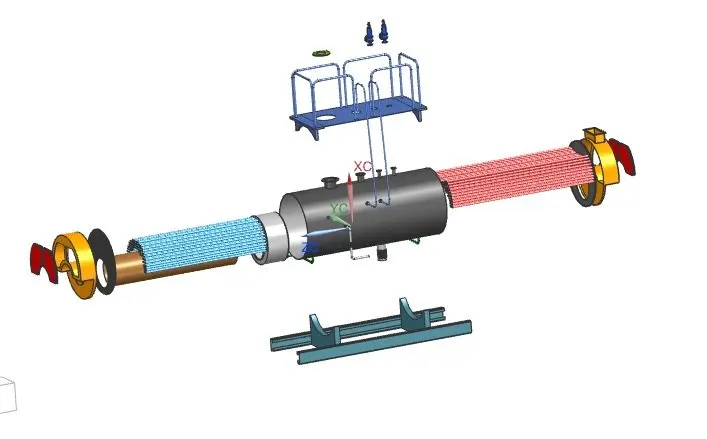
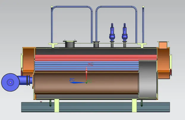
Section view
Conclusion
Thus the boiler for the petrochemical plant was designed considering the various design standards for boiler construction. The capacity of the boiler is 8TPH and fuel oil is
used as combustion fuel. The fuel oil has lesser inflammability than other fuels. The suitable pump to supply the feed water was chosen. The dimensions of the shell,
furnace, fire tubes etc, are calculated according to the ASME standards. The proper materials were chosen for safe operation of the boiler. The overall efficiency of the
boiler is 81% after considering the various losses happening during the combustion and heat transfer. The boiler must be manufactured with great care and the testing is
normally done by a third party. The overall efficiency can be used by air pre-heating, using XI-D tubes, and economizer. The proper feed water quality and safety
standards must be followed for proper functioning of the boiler. The blowdown of the boiler should be scheduled and done on regular basis. The CAD modeling and the
assembly were done using the NX-CAD software. The bottom-u-p assembly approach was used.
References
- https://savree.com/en/3d-models/fire-tube-boiler-3-pass
- https://www.researchgate.net/publication/320994611_Improvement_of_fire-tube_boilers_calculation_methods_by_the_numerical_modeling_of_combustion_processes_and_heat_transfer_in_the_combustion_chamber
- https://www.engineeringtoolbox.com/saturated-steam-properties-d_457.html
- https://www4.eere.energy.gov/manufacturing/tech_deployment/amo_steam_tool/equipBoiler
- https://www.powermaster.com.mx/pdf/Hojas%20Esp%20Tec%202021%20Junio/WB-A2-3P/Ingles/Specifications%20WB_A2_3P_15_PSIG.pdf
- https://firecad.net/engineering-calculations/
- https://www.thermaxglobal.com/wp-content/uploads/2020/04/Shellmax-Global.pdf
- https://www.spiraxsarco.com/learn-about-steam/the-boiler-house/boiler-efficiency-and-combustion#article-top
- https://www.engineeringtoolbox.com/water-specific-volume-weight-d_661.html?vA=100&units=C#
- https://www.researchgate.net/publication/343111881_Designing_of_a_Fire_Tube_Boiler