Roof challenge
Roof Design
Objective
- To develop the essential flanges and reinforcements for the given roof styling.
- To do the Draft analysis and section inertia at 0-Y section
- To calculate the Heat distortion and snow load on the roof.
- To do a curvature study on the roof and calculate the position of the bow roof.
- To consider DFM,DFA while designing the parts.
Introduction
Roof
An automobile roof or car top is the portion of an automobile that sits above the passenger compartment, protecting the vehicle occupants from sun, wind, rain, and other external elements.
Types of Roof
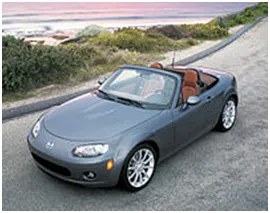
Convertible Roofs
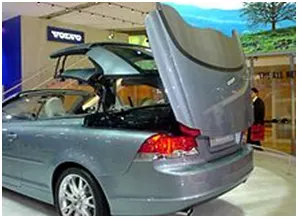
It is a passenger car that can be driven with or without a roof in place. It provides an open air driving experience. They can be made in retractable or detachable hardtops. The major drawback is that it reduces the structural rigidity.
Hardtop Roof
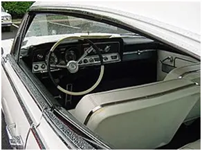
A hardtop is a rigid form of automotive roof, which for modern cars is typically constructed from metal. A hardtop roof can be either fix, detachable for separate storing or retractable within the vehicle itself. Pillar less hardtop is a body style of cars without a B-pillar.
Sunroofs
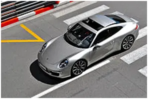
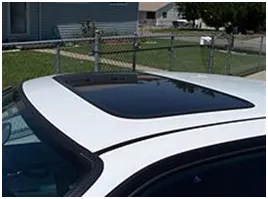
A sunroof is a movable panel that opens to uncover a window in an automobile roof, allowing light and/or fresh air to enter the passenger compartment. Sunroofs can be manually operated or motor driven, and are available in many shapes, sizes and styles.
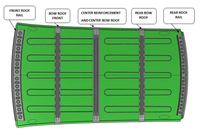
Parts and their description
Front Roof Rail
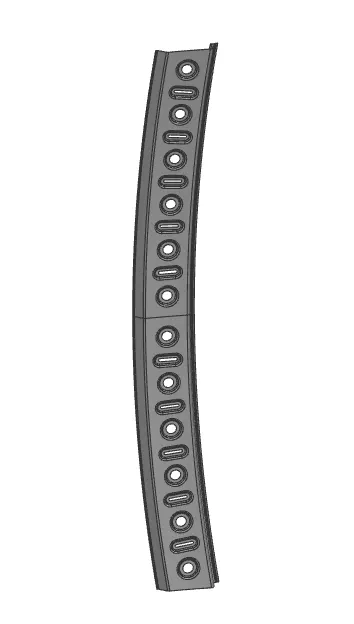
The front roof rail is located at the front end of the roof and It accommodates the wind shield and A-pillar mounting and they are joined with the flanges with the car’s body.
Bow Roof Front and Bow Roof Rear
These Bow roofs are placed in between the front roof rail, rear roof rail and centre reinforcement. These bow roofs add strength to the roof and also aid in proper weight distribution.
Rear Roof Rail
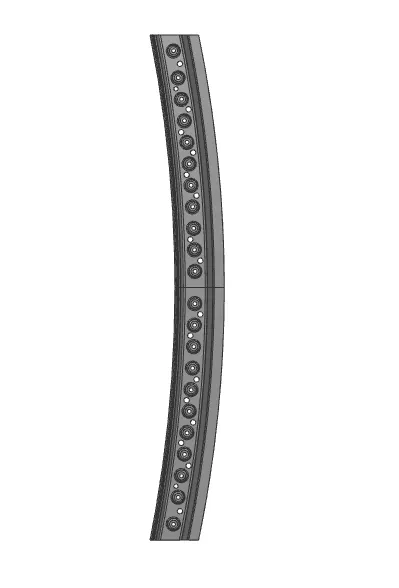
It is located at the rear end of the roof. It joins with the body side and also houses the tail gate.
Front Roof Rail Rear Roof Rail
Rear Bow Roof Front Bow Roof
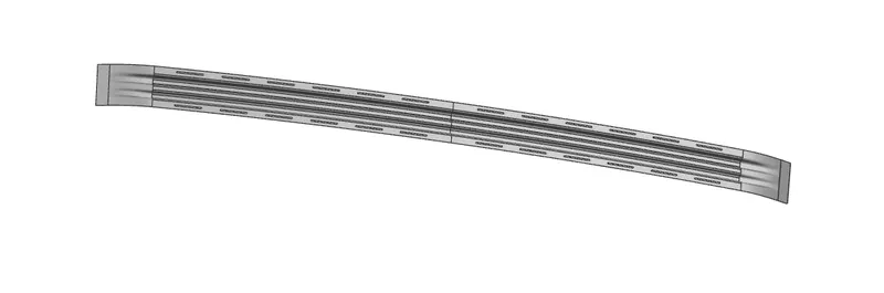
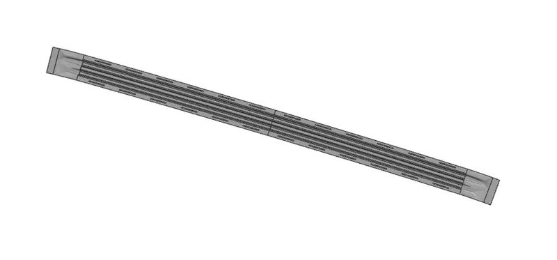
Center Reinforcement and Center bow Roof
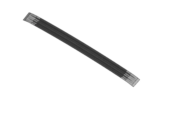
Roof Assembly /Joining process
Mastic Sealants
The outer panel is one of the major styling surfaces, so the traditional fastening or joining techniques like welding or nuts and bolts cannot be used. As they could reduce the cosmetic looks, hence a epoxy based adhesives are used for joining the outer panel to the inner panel. This can also be used to bond steel and aluminum sheets. They provide increased stiffness and enhanced corrosion protection of hem flange. The applied mastics sealants have strengthening or bonding influence up to 80 mm diameter.
Spot Welding
Spot welding is the type of resistance welding when the thermoelectric heat is generated, sequentially at a number of isolated points or spots, where the mating surfaces are pressed together by an external force during the whole welding process.The spot welding is used to join the reinforcements and bow roofs to cars body where they are not exposed to view but covered by other flanges.

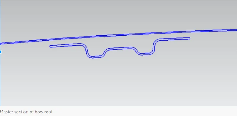
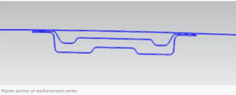
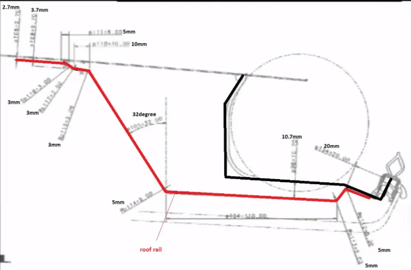
Master Sketches
- The mater sketches provide dimension for designing based on all the design, safety and functional requirements.
- All the Bow roofs and roof rails are give 0.75mm thickness.
Front Rail Roof Master
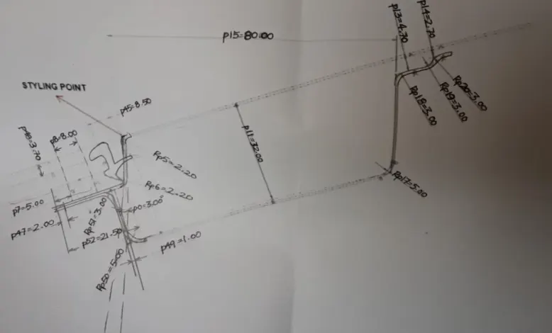
Bow Roof Master Sketch
Center Reinforcement master sketch
Rear Rail Roof Master Sketch
Design Parameters
- Head Clearance
- Visibility Criteria
- Roof Crush test
- Heat Distortion criteria
- Snow load Criteria
- Curvature study
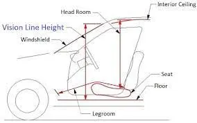
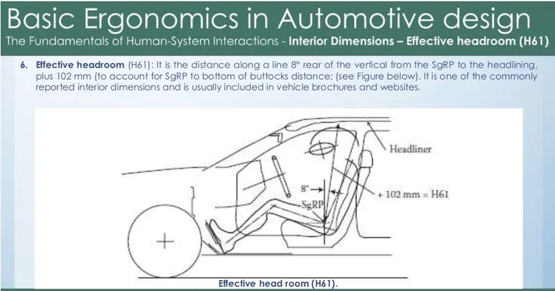
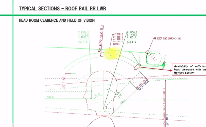
Head Clearance Criteria
- Headroom is measured as the distance from a car's roof to its seat bottom. It is also calleds as torso room. The maximum and minimum values are published, since most cars have seats that adjust up and down.
- The Head room clearance is dependent on the windshield angle, height of the seat and interior ceiling and roof liner.
- For Normal height occupants cars with 38 in clearance will be sufficient, but for taller occupants cars with clearance of upto nearly 43in can be considered.
For example:-
2019 Nissan Pathfinder Head room: 42.2″ and Leg room: 42.2″
2019 Ford Expedition Head room: 42.0″ and Leg room: 43.9″.
Visibility Criteria
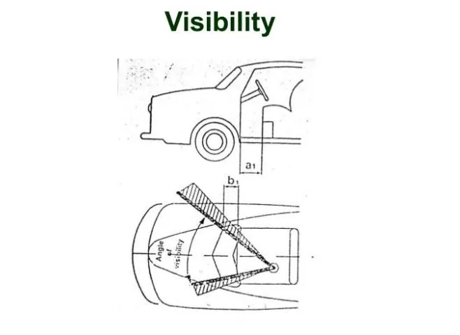
- The Visibility criteria is the maximum distance at which the driver of a vehicle can see and identify prominent objects around the vehicle.
- The parts of a vehicle that influence visibility include the windshield, the dashboard and the pillars.
- Good driver visibility is essential to safe road traffic and safely manuever the vehicle safely to the destination.
- The visibility, ingress, egress are interelated for the occupant in the car. for instance if the occupant is placed close to the windshield then visibility increases but the ingress and egress of the occupants becomes difficult and vice versa.
Roof Crush Test
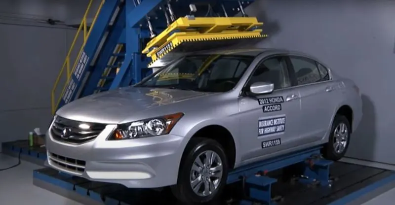
- Roof crush is the failure and displacement of an automobile roof into the passenger compartment during a rollover accident. the rollover accident is found more fatal than the other type of road accidents. The injury caused to the passengers is directly linked to the amount of roof intrusion in to the passenger compartment during the roll over.
- The best way to prevent the injuries is to stop vehicles from rolling over. In modern vehicles it can be achieved by providing the features like Electronic stability control (ESC), side curtain air bags and the occupants must wear seat belts.
- In the test conducted by the IIHs (Insurance Institute of highway safety) the basic points of consideration are
- How quickly the car regains its original position after the rollover
- The depth of protrusion in the passenger compartment.
But for these features to work effectively the roof by itself should be sturdy enough so it can prevent ejection of occupants through the windows, door or windhield in case of roof deformation due to rollover.
Types of roof crush test
The roof crush test is done in two methods.In first case the all the doors and windows are locked and the force is applied. For the second case the car chassis or sill is fixed on a horizontal surface and force is applied from top.
Method of force application
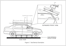
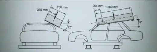
The load is applied to the roof by pushing an angled metal plate down on one side of the roof at a slow but constant speed and measuring the force required to crush the roof and it is 25 deg tilted from the front end. the metal plate is 750 mm wide and 1800mm long. The load is applied is applied for 120 seconds and peak strength to weight ratio is calculated.
Inference
According to the IIHSa good rating requires a strength-to-weight ratio of at least 4. In other words, the roof must withstand a force of at least 4 times the vehicle's weight before the plate crushes the roof by 5 inches. For an acceptable rating, the minimum required strength-to-weight ratio is 3.25. For a marginal rating, it is 2.5. Anything lower than that is poor.
So while designing the roof the proper placement, thickness, mastic points of the bow roof must be considered for optimized design and adding strength to the roof.
Heat Distortion Criteria
For the efficient design and proper strength of the roof the bow roofs has to be placed by considering the Criteria like heat distortion and snow load. From Heat distortion criteria, roof strength can be enhanced by appropriate positioning of bow roof rails.The roof is directly exposed to the sun which causes the thermal stresses in roof. Heat distortion temperature is the temperature at which metal softens and deforms under a specified load. Hence For the proper placement and to avoid the damages to the roof heat distortion has to be calculated.
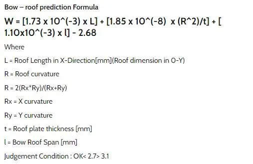
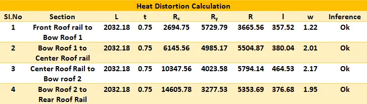
From the above tabulated results we can see the results are within the expected range and hence we can say the present placement of bow roof is good and it would provide proper strength and heat distortion to the roof.
Snow Load Criteria
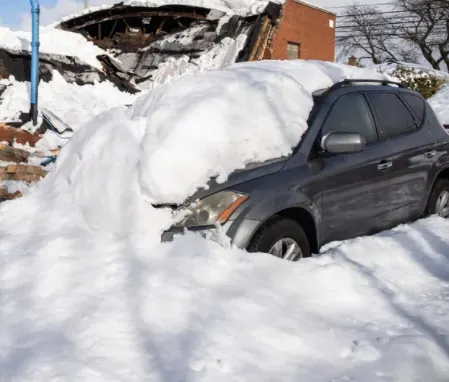
Snow load is the downward force on a cars roof by the weight of accumulated snow and ice. The roof or the entire structure can fail if the snow load exceeds the weight the roof was designed to shoulder. So the proper strength has to be given to the roof by providing the necessary bow roofs and mastic sealants.
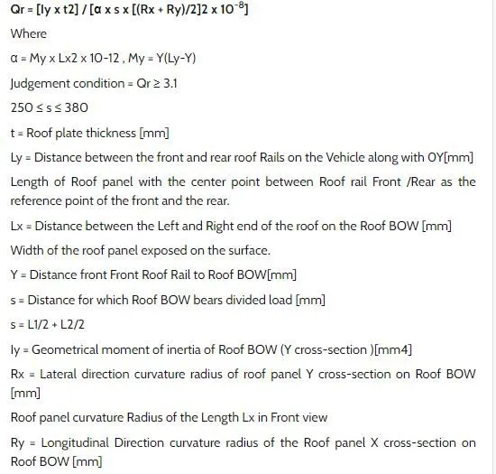
Formula
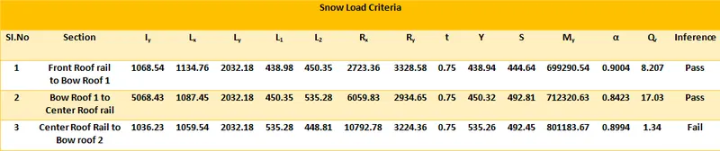
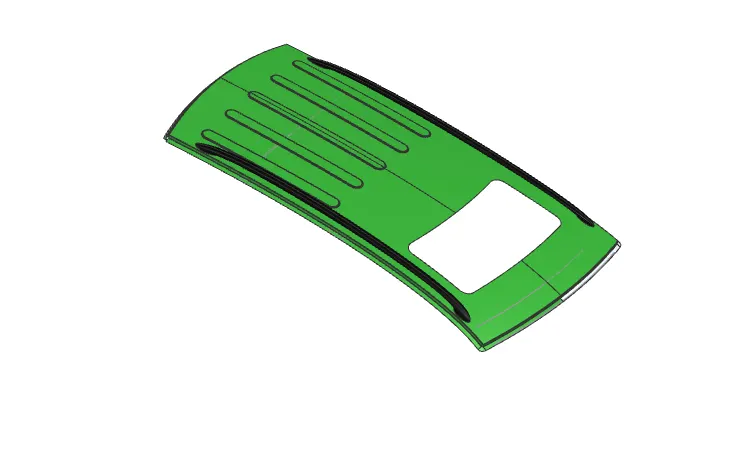
From the above tabulated results we can see the results are within the expected range, except the third case. since the third case fails embosses are provided on the outer roof to improve the strength of the roof.
Section Modulus Calculation
Section modulus is a geometric property for a given cross section used in design of beam or flexural members. The relationship between the other geometric properties used in design properties like radius of gyration for compression, moment of inertia and polar moment of inertia for stiffness, area for tension and shear are dependent on the shape of the object considered.
Types of Section Moduli
- Elastic Section Modulus
- Plastic Section Modulus
Formula to calculate the section modulus
Section Modulus is the measure of strength of cross sectional area of an object about the neutral axis, hence increase in the cross sectional area there increases the strength but also increases the overall mass of the object.
S = I/y
I = Second Moment of inertia or Area moment of inertia.
Y = distance from neutral fibre to the most extreme fibre.
Front bow Roof
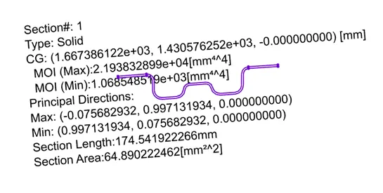
Maximum Moment of Inertia
S = I/y = 2.193*104(mm4) / 33.42 (mm)
Smax = 656.19 mm3
Minimum Moment of inertia
S= I/y = 1068.54 (mm4) / 33.42 (mm)
Smin = 31.97 mm3
Centre Reinforcement and centre Bow roof
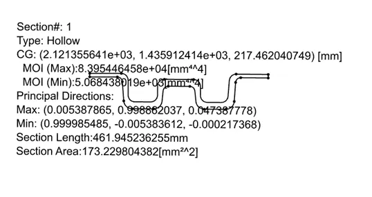
Maximum Moment of Inertia
S = I/y = 8.3954*104(mm4) / 39.4 (mm)
Smax =2130.8 mm3
Minimum Moment of inertia
S= I/y = 5068.43(mm4) / 39.4 (mm)
Smin = 128.64 mm3
Rear Bow Roof
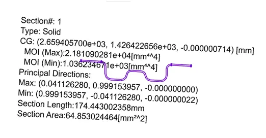
Maximum Moment of Inertia
S = I/y = 2.181*104(mm4) / 33.85 (mm)
Smax = 652.94 mm3
Minimum Moment of inertia
S= I/y = 1036.23 (mm4) / 33.85 (mm)
Smin = 30.61 mm3
Front Roof Rail
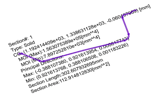
Maximum Moment of Inertia
S = I/y = 1.563*104(mm4) / 61.18 (mm)
Smax = 255.47 mm3
Minimum Moment of inertia
S= I/y = 7897.25 (mm4) / 61.18 (mm)
Smin = 129.08 mm3
Rear Roof Rail
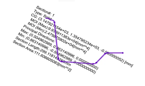
Maximum Moment of Inertia
S = I/y = 9.933 *104(mm4) / 51.45 (mm)
Smax = 1927.24 mm3
Minimum Moment of inertia
S= I/y = 24798.7 (mm4) / 51.45 (mm)
Smin = 481.96 mm3
Draft Analysis
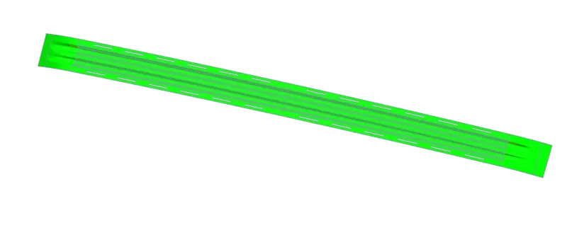
To ensure the drawability of the parts the draft analysis is done and the green color indicated that the part is drawable and the red or blue shows the parts with negative draft.
Front Roof Rail
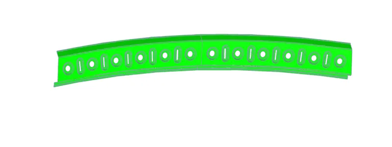
Rear Roof Rail
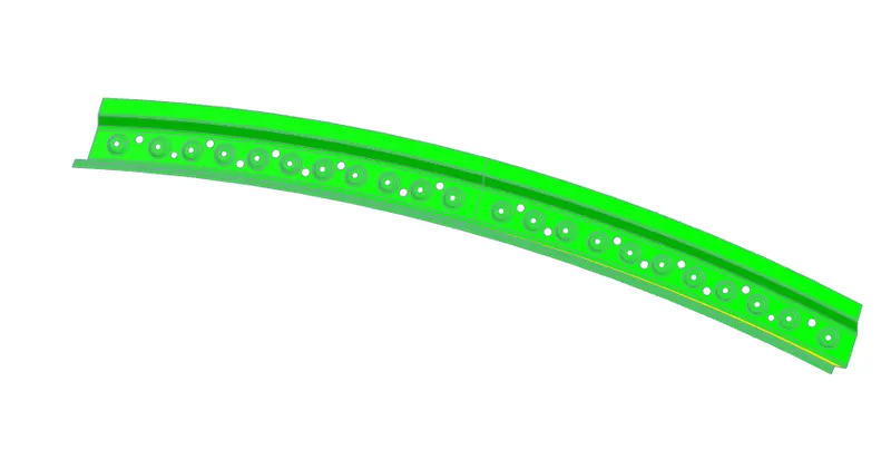
Centre Bow Roof
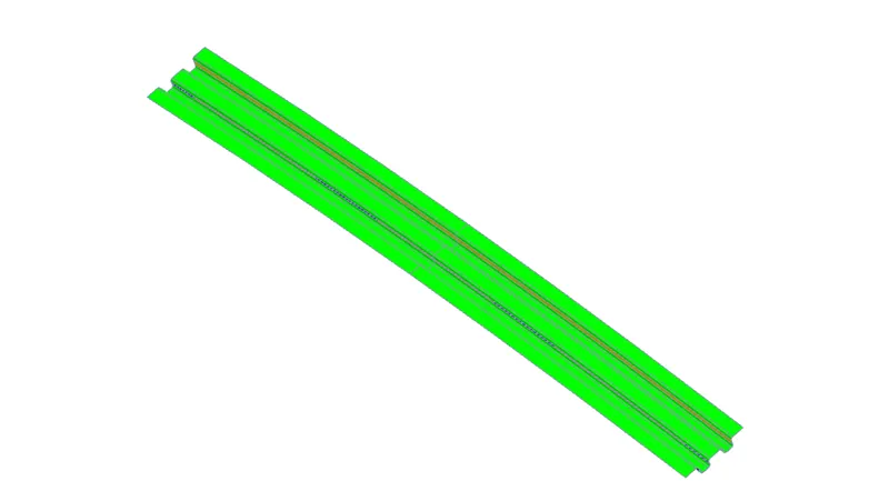
Front Bow Roof
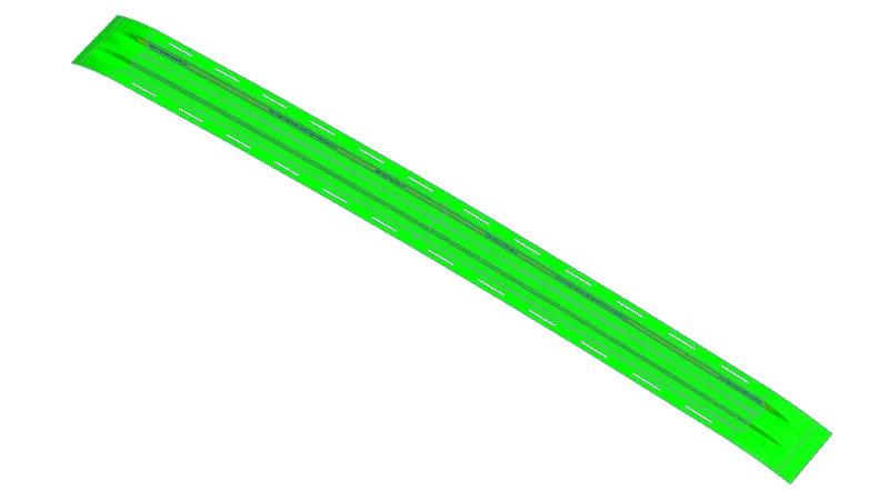
Rear Bow Roof
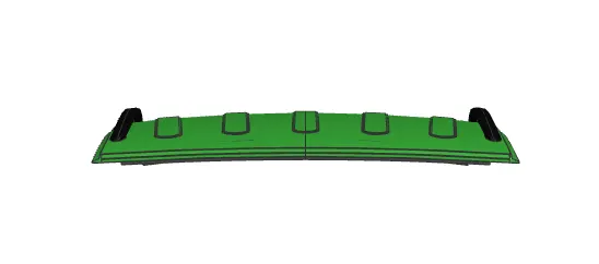
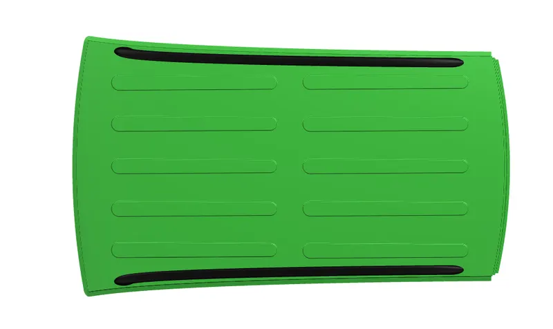
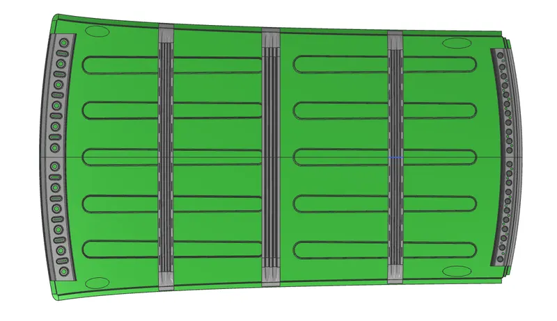
Roof Assembly Images
Front View
Top View
Bottom View
Roof with Sunroof
Conclusion
Thus the roof rails and reinforcements were designed with the styling provided considering the roof design parameters DFM, DFA and nx cad tools required were also learned.