Draft Analysis on a Fan Cover
AIM:
To create the tooling axis for the given Fan cover model meeting the requirements of the draft angle and perform the Draft analysis on the model.
PROCEDURE:
STEP 1
Load up the Fan Cover IGES part file in Catia
STEP 2
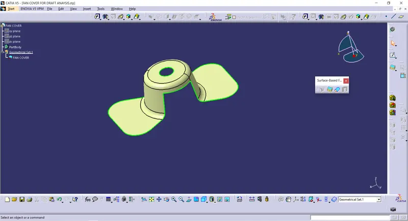
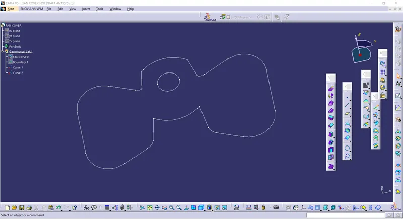
Check there is no gap inside the component. Can be check visually or can use JOIN command to rectify any discontinuities. For this, Boundary command command can also be used.
STEP 3
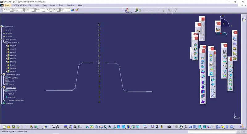
Create a dummy tooling axis. This axis will help in the creation of tooling axis in both X and Y direction.
Dummy axis is created through the center point of the circular hole which is no top of the class A surface.
For the tooling axis, Z direction is choosen because from X and Y direction its seems difficult to tool the part.
STEP 4
Real tooling axis is obtained by using the Bisect command.
- An axis system is made intersecting ZX plane with the component. As a result gets a curve.
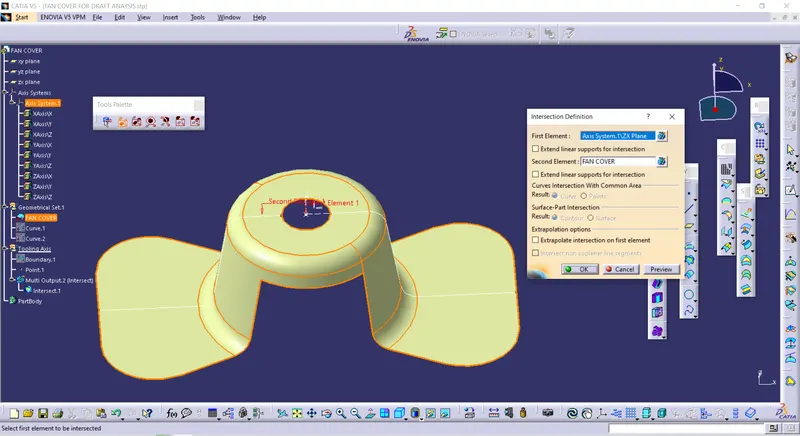
- Here two sides of the components which are inclined in a particular angle seems difficult to tool.
- Two lines are made with angle same as the sides of the components by using point to point method utelising the points on the curve obtained by intersecting the component with ZX plane.
- By using these lines axis for X and Y direction is made.
STEP 5
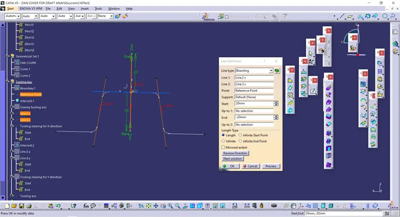
Tooling axis for X direction
- Using the curve obtained from instersecting ZX plate with the component , two lines are obtained .
- Bisecting those two lines, a line in formed. That is the tooling axis for X direction.
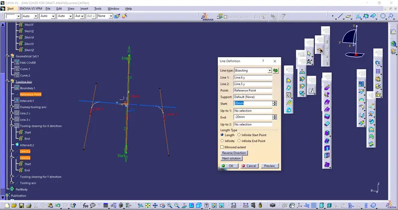
Tooling axis for Y direcction
- Using the curve obtained from instersecting YZ plate with the component , two lines are obtained .
- Bisecting those two lines, a line in formed. That is the tooling axis for Y direction.
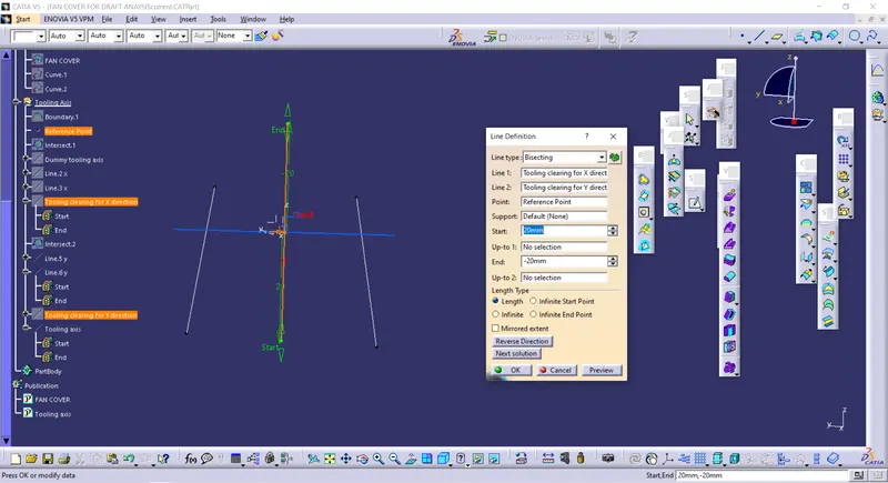
Final tooling axis
- By bisecting X and Y tooling axis, final tooling axis is obtained.
STEP 6
Draft Analysis
- Various draft analysis can be accessed by usinf Feature Draft Analysis command under Insert tab.
- By clicking the compass icon fron the Fearure draft analysis dialogue box, align the axis with the red dot with the tooling axis.
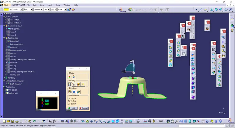
fig: compass feature
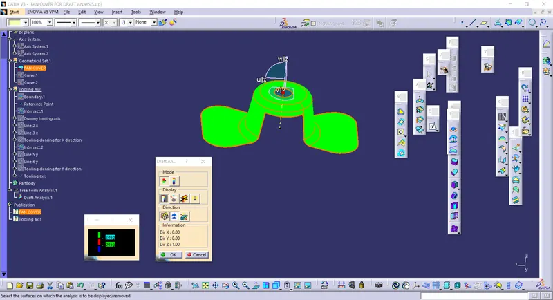
fig : locked draft direction
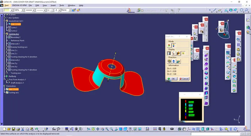
fig : Colour scales: Analysis after changing the draft angle to 20-20 degrees
**before we set the minimum draft angle as 3 degrees.
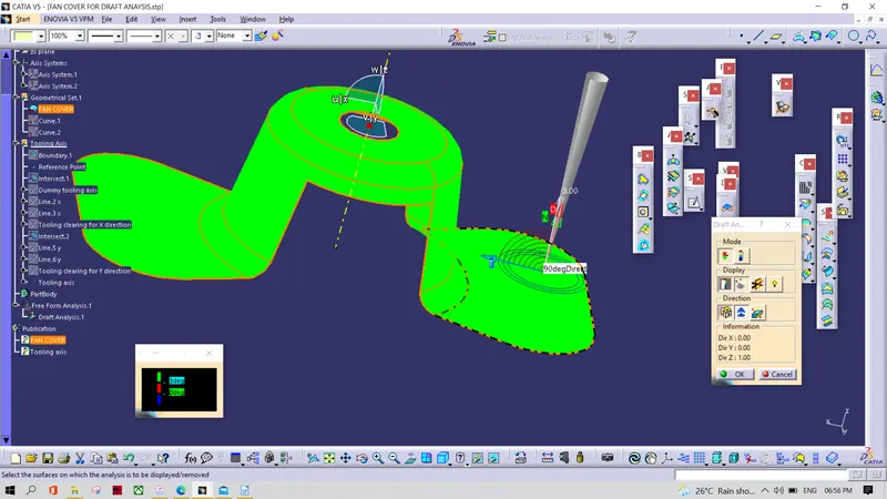
fig : Manual draft angle analysis.
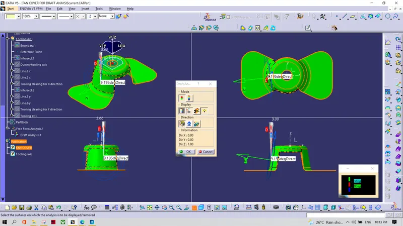
fig: Views
RESULT
After running the Feature draft analysis command we can check the draft angle and make sure that that the component is okay for tooling. The green colour on the component means angle of the face is greater than the provided in draft angle. If its red then its less than the required draft angle.