Section Modulus calculation and optimization
SECTION MODULUS CALCULATION AND OPTIMIZATION
AIM
By using the section of the Hood design, calculate the section modulus. Also come up with a new section that has an improved section modulus compared to the previous one.
THEORY
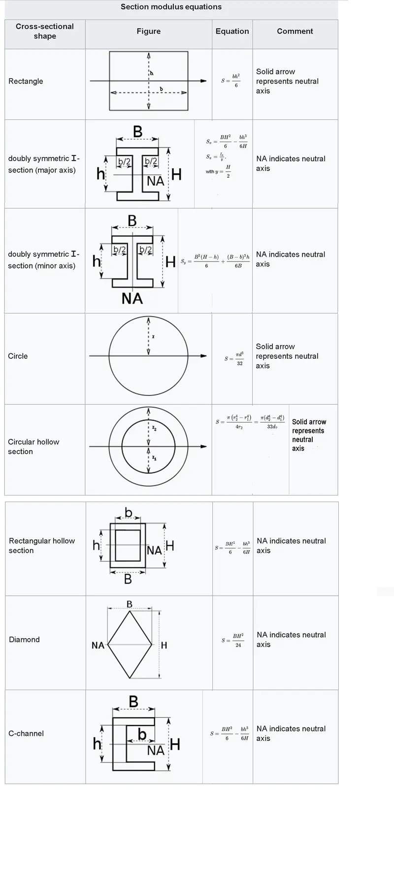
Section modulus is a geometric characteristic for a given cross-section that is utilised in beam or flexural member design. Area for tension and shear, radius of gyration for compression, and moment of inertia and polar moment of inertia for stiffness are all geometric parameters utilised in design. Any link between these features is strongly influenced by the form. Section moduli are classified into two types: elastic section moduli and plastic section moduli. The section moduli of various profiles can also be obtained as numerical values for popular profiles in tables that detail their features.
ELASTIC SECTION MODULUS
The elastic section modulus is utilised in general design. For the most common materials, it is relevant up to the yield point.
S = I / y is the elastic section modulus.
where I is the second moment of area (not to be confused with moment of inertia)
y is the distance from the neutral axis to any particular fibre. It is frequently stated as y = c,
where c is the distance between the neutral axis and the most extreme fibre.
It is also frequently used to calculate the yield moment (My), such that My = S ⋅ σy,
where y is the material's yield strength.
PLASTIC SECTION MODULUS
When elastic yielding is allowed and plastic behaviour is regarded as an acceptable limit, the plastic section modulus is used for materials. Designs frequently seek to minimise permanent deformations by staying below the plastic limit, occasionally assessing the plastic capacity against amplified pressures or stresses.
The plastic section modulus is affected by the position of the plastic neutral axis. The plastic neutral axis is the axis that divides the cross section so that the compression force from the compressed area equals the tension force from the tension region. Thus, the region above and below the plastic neutral axis will be identical for sections with constant and equal compressive and tensile yielding stress, but this is not necessarily the case for composite sections.
The plastic section modulus is the sum of the cross-sectional areas on either side of the plastic neutral axis multiplied by the distance between the two regions' local centroids:

Why section modulus is calculated for certain automotive parts?
- Section modulus calculation is very important in structural engineering.
- Its very crucial when it comes to the design of beams and parts which can flex.
- The higher the value of the calculated section modulus value, the more it can take larger loads and can maintain its shape without getting bended.
- When it comes to automotive parts, steels are the main raw material. It’s easier to calculate the section modulus of steel as its stress and exact measure of strength can be calculated easily because of its geometric property.
How section modulus is calculated?
- The calculation is carried out for the cross section of the part.
- If the part is symmetrical in shape, the section modulus value can be considered for both up and down form the neutral fibre.
- If the part is asymmetrical in shape, the section modulus values will be multiple for top portion and bottom portion from the neutral axis. That is for max value it will be Smax and min value will be Smin.
SECTION MODULUS CALCULATION FOR THE CAR HOOD USING CATIA
- Here I am going to calculate the section modulus of the car hood I designed. After doing that, I am going to modify the part to further improve the section modulus value.
CASE 1
Step 1 :Here I am calculating the section modulus values of the part as it is without making any changes to the part at all.
Step 2 :first importing the model to the Catia and using intersection 3D element function in sketcher workbench, a section of the part is obtained.
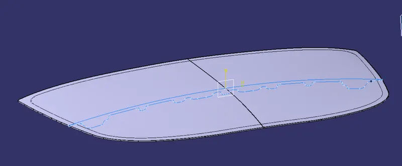
Step 3 :Next make the obtained sketch closed, as some portions of the sketch maybe discontinuous due to the design.
Step 4 :After making the sketch closed, using the fill command, sketch is filled up

Step 5 :Now the section modulus for the filled surface is calculated using the measure inertia command.

Step 6 :By doing that we will get two values, M1 and M2. The M1 is the minimum value and M2 is the maximum value
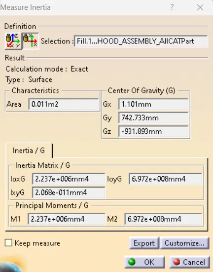
We consider the minimum value as it the value point it will get deform. After this point the part will undergo deformation.
- The result for the section modulus for case 1 is given below.
M1 =2.237e+006mm4
M2= 6.972e+008mm4
CASE 2
We are going to do the same steps that we done in the first case but here we are making some changes in the sketch to study the changes in the section modulus. By doing so we can get an idea on how to improve the design for better strength for the part
- For comparison the blue line is the unedited sketch and the white sketch is the modified sketch.
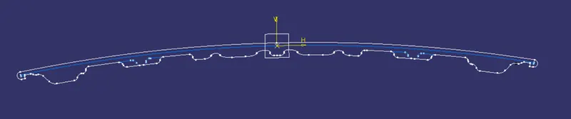

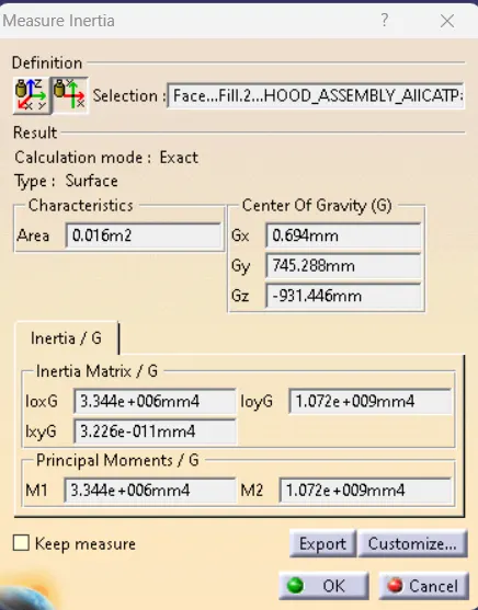
- The result for the section modulus for case 2 is given below.
M1 = 3.344e+006mm4
M2= 1.072e+009mm4
Percentage of Increase Between case1 and case 2
% change = (case 2 - case 1) / case 1 x100
= 1107000/2237000 x 100
= approx 49% difference by increasing the thickness and improving the embosses.
CONCLUSION
We did the section modulus calculation on our CATPart and also, we did some modifications on the thickness and the embosses. By doing so we found out the impact it makes on the section modulus value for the part. The thickness of the part is mostly standard. But we can always improve the embosses. So, by doing this project we observed that a good inner body design is very important in improving the overall strength of the part.
Reference : Wikipedia