Coin Holder Design
Aim
to create the coin holdr plastic componet through the given class A surface and carryout draft analysis on the model to make sure all the requirements are met.
Procedure
Step 1
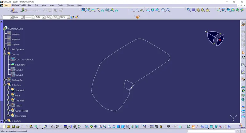
Import the given class A to the Catia workbench and make sure it is having a closed boundary
Step 2
Tooling axis
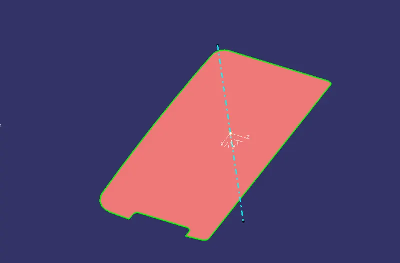
Extract the base from the class A surface. Create a point on the center of the extracted base. Then create a new axis system on based on that point as an origin. After that, create a line perpendicular to the extracted base surface through the point.
Step 3
B Surface Creation
Base B surface
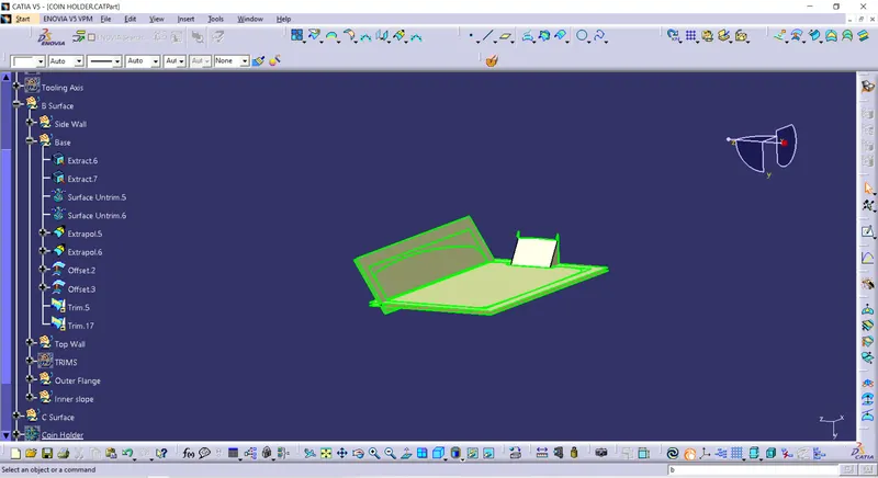
Base of the component is made by extracting the parts from the class A , trimming , extrapolated and then trimmed to obtain the base portion. Then it is offset ed to obtain the B surface.
Side wall B surface
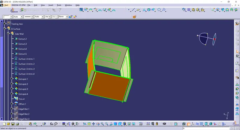
Side wall of the component is made by extracting the parts from the class A, trimming , extrapolated and then trimmed to obtain the side wall. Then it is offset ed to obtain the B surface.
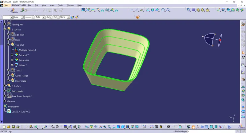
Top wall B surface
Top wall of the component is made by extracting the parts from the class A using multiple extract and extrapolated to obtain the top wall. Then it is offset ed to obtain the B surface.
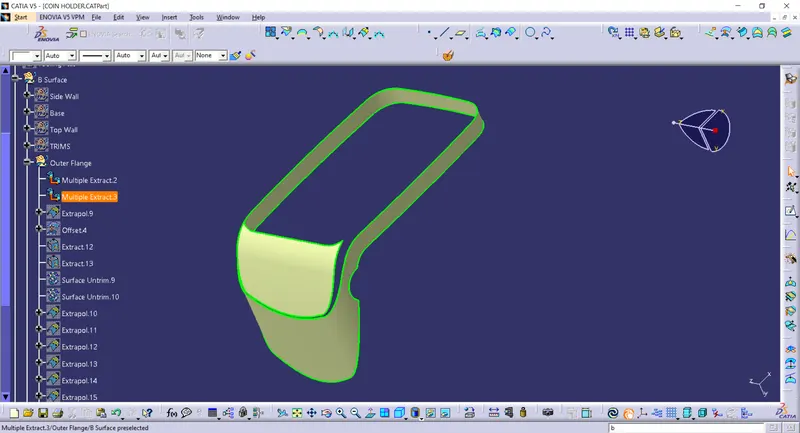
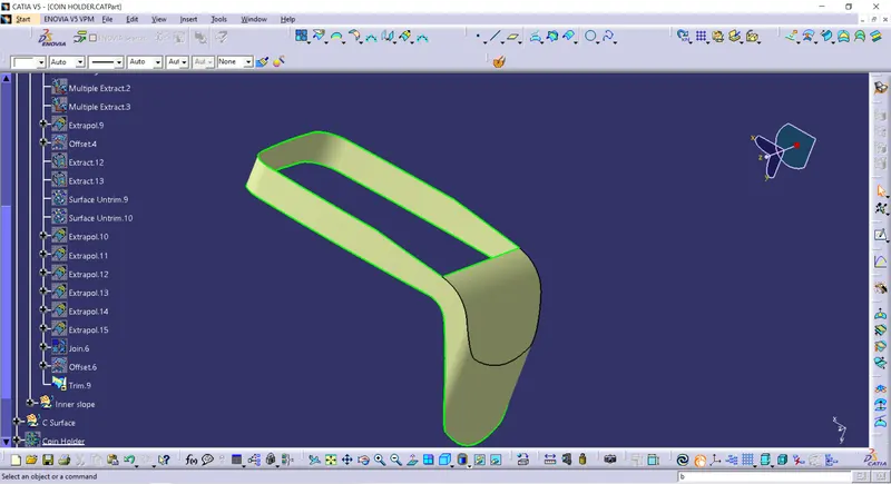
Outer flange B surface
Outer flange of the component is made by extracting the parts from the class A using multiple extract, untrimmed and extrapolated to obtain the outer flange. Then it is offset to obtain the B surface.
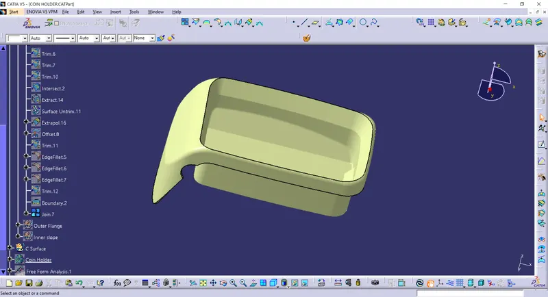
Final B surface
Finally, all the individual parts are trimmed together to get the B surface of the component. Fillets are also given to the edges
Step 4
C Surface Creation
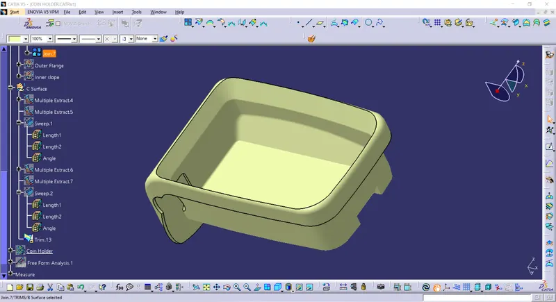
from the class A, the boundary is extracted along with the near surface. Then using sweep command using the sub type “with reference surface” selecting boundary as the guide curve, and the surface as the reference surface, sweep to obtain the c surface. Same is done for the hole also.
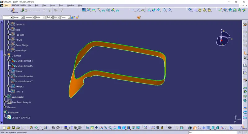
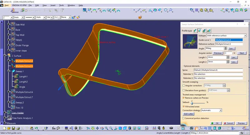
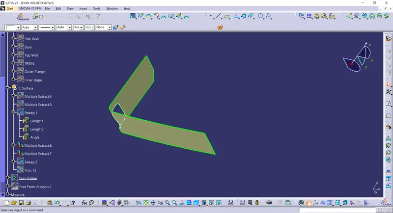
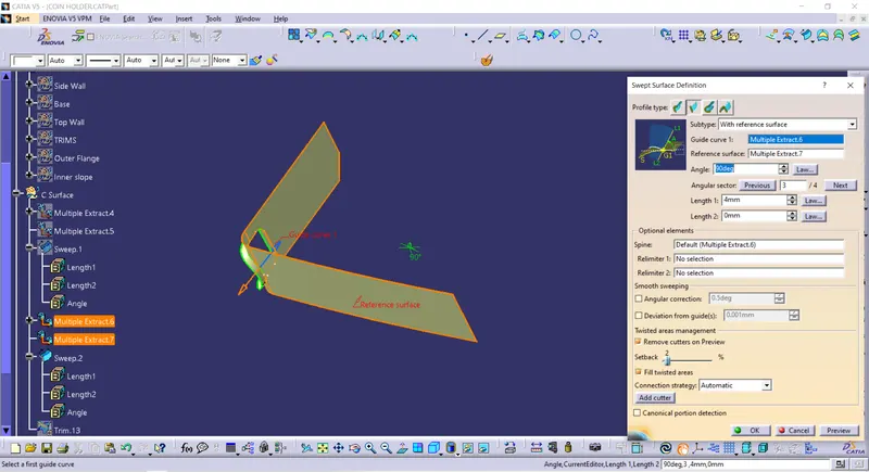
All the surfaces are trimmed together to obtain a closed surface.
Step 5
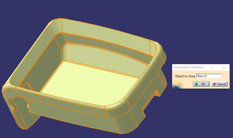
Closed Part Body
By going to the part design workbench thicken the closed body and create a solid part body
Step 6
Draft Analysis
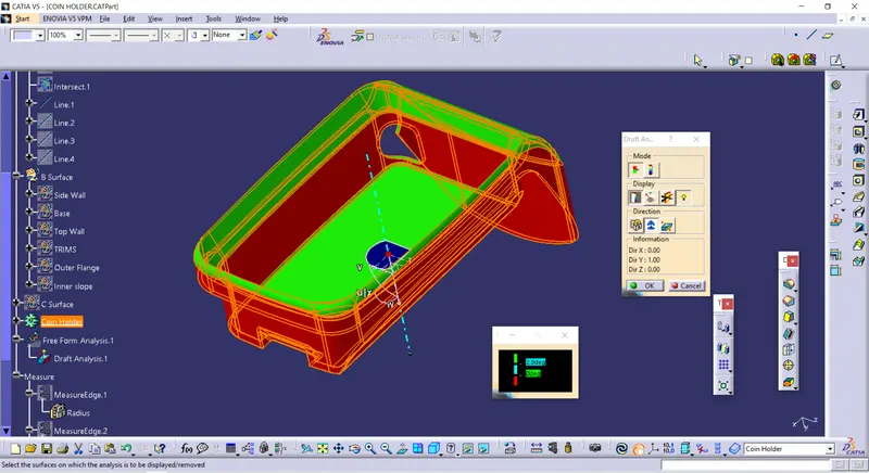
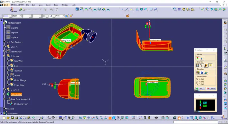
Draft analysis is carried out on the component to make sure the draft angles are following the regulations
Conclusion
- A close body is created using the given class A by generating B surface and C surface and merging A B and C surface together.
- Draft analysis is carried out on the model and completed successfully.