Week -2
1.SIMULINK MODEL OF A DOOR BELL USING SOLENOID BLOCK .
Aim
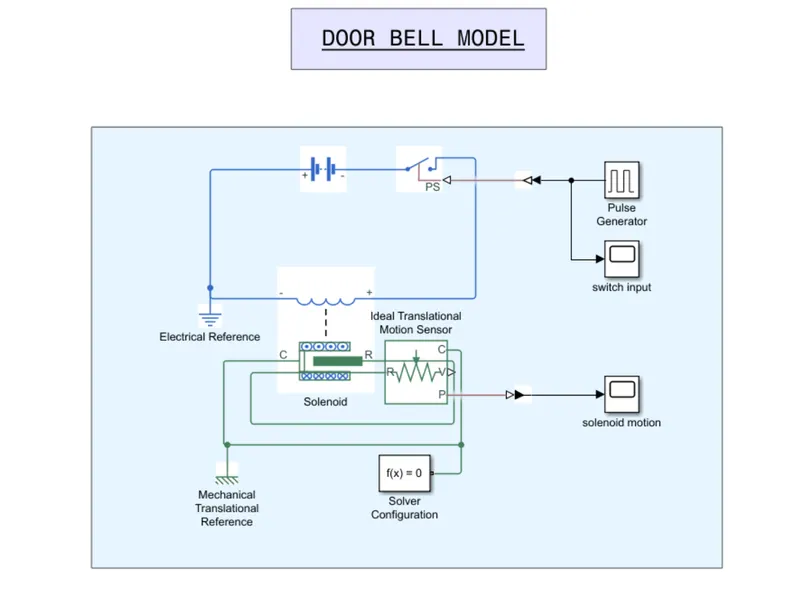
To make a solenoid block using solenoid blocks. When the switch is closed the electromagnet should receive electrical power from the battery and pull the metal arm to hit the bell to produce the sound.
The switch is closed for 2 seconds and then released to make the plunger move.
Theory
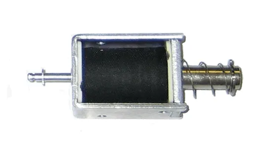
To understand the working of this model, we should know about the solenoid. Solenoid is basically a device that converts the electrical energy to mechanical energy using the concept of electromagnetism. When electric current is passed through a solenoid , the device makes a magnetic field which is used to create a linear motion. If there is no power, the plunger inside the solenoid will stick out. When power is applied, the plunger will go inside due to the magnetic field produced at that instant.
Model and Working Explained
Working
The model has been created to satisfy the description we aimed to achieve. Here we used blocks such as :
- Pulse generator
This block will generate a pulse according to the parameters we input. We can basically replicate any type of signals using a pulse generator. Here we want to replicate the event of on/off of the switch.
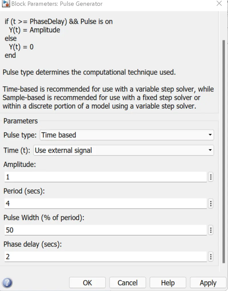
We want the switch to be engaged for 2 seconds. A phase delay of two seconds will generate a pulse with the delay of 2 seconds.
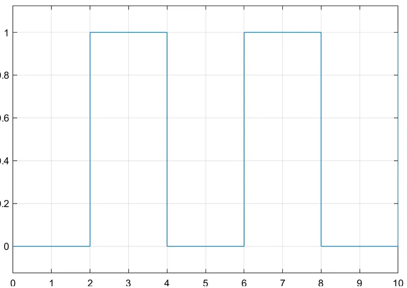
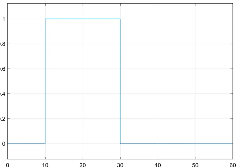
This graph is a direct representation of the signal gave out by the pulse generator.
- Switch
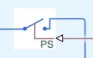
The switch in this model is used to trigger the solenoid by passing and cutting the power supply to the solenoid by opening and closing the circuit according to the conditions gave to the pulse generator.
- Battery

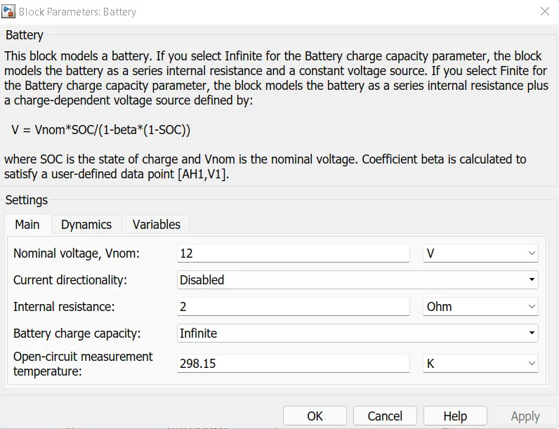
Battery is the preferred power source for this model. The battery will provide the power for the whole setup. Here a 12v battery is provided.
- Electrical reference
Electrical reference will act as an electrical ground.
- Solenoid
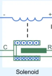
The solenoid block will hit the plunger to make the sound when the power is supplied.
- Ideal translational motion sensor
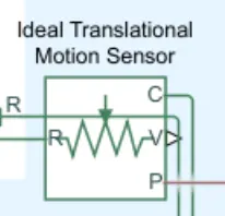
This block can be used to analyze the motion of the solenoid plunger.
- Mechanical translational reference

This block represents a mechanical translational reference point, that is, a frame or a ground. Use it to connect mechanical translational ports that are rigidly affixed to the frame (ground).
- Solver configuration
The Solver Configuration block specifies the solver parameters that your model needs before you can begin simulation.
Result & Conclusion
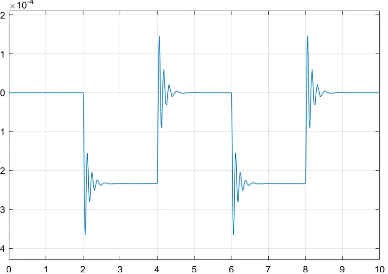
As we can see the, the ideal translation motion sensor detects motion every 2 seconds
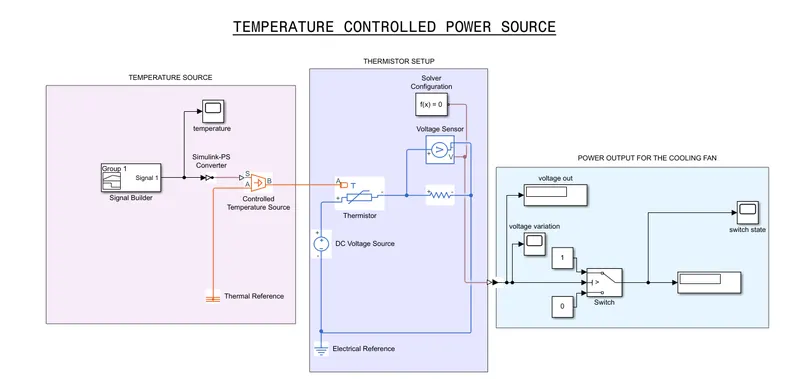
2.Using a thermistor to sense the temperature of a heater and turn on and off the fan.
Condition
- Temperature source
- 0-10 sec - 20 degree celsius
- 10-30 sec -27 degree celsius
- 30-50 sec - 23 degree celsius
- The fan should turn on if the temperature hits 25 degC or more, and remain off if temperature goes below that.
Theory
Thermistor
A thermistor is basically a resistor whose resistance is varied depending the temperature.
Thermistors can be divided into two based on their conduction model.
- Negative temperature coefficient (NTC)
Has less resistance at high temperatures. These are widely used as inrush current limiters, temperature sensors etc..
- Positive temperature coefficient (PTC)
Has more resistance at high temperatures. These are used as self resetting overcurrent protectors and self regulating heating elements.
Model & Working Explained
- Signal builder
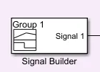
Using a signal builder, input for the controlled temperature source is given. Unlike a pulse generator, we get a little more flexibility while making the signals as we need to make signals with a lot of variations.
- Controlled temperature source
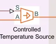
After getting the input from the signal builder, the controlled temperature source will simulate a temperature output according to the inputs given. The controlled temperature source will mimic a real world temperature source.
- Thermal reference
This block represents a reference point in a thermal network where the temperature is equal to absolute zero.
- Thermistor
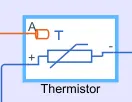
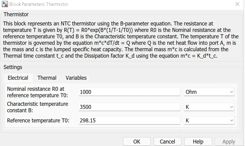
The thermistor will observe the temperature variations and provide resitance until the reference temperature. The reference temperature is set to 298K /25degC. Here a NTC thermistor is used.
- Dc voltage source
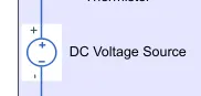
For this circuit to operate the fan, a dc voltage source is provided. This can circulate a voltage of 25v through the circuit.
- Electrical reference
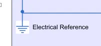
Electrical reference will act as an electrical ground.
- Solver configuration
The Solver Configuration block specifies the solver parameters that your model needs before you can begin simulation.
- Voltage sensor
The block represents an ideal voltage sensor, that is, a device that converts voltage measured between any electrical connections into a physical signal proportional to the voltage.
- Resistor
This block represents a linear resistor.
- Switch
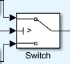
The Switch block passes through the first input which is the constant 1 or the third input signal which is the constant 0, based on the value of the second input which represents the voltage data output of the voltage sensor. The first and third inputs are data input. The second input is a control input. We analyzed the voltage through the circuit when the temperature reaches 25 degree celsius is 0.02294. So we give the threshold value around that number. As a result the constant 1 will execute when the circuit reaches 25 degrees else constant 0 will execute.
- Constant
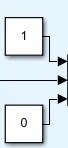
Output the constant specified by the 'Constant value' parameter.
- Display
Display input values. If the incoming signal is of type string, the 'Numeric display format' parameter selection does not affect the display of the string.
- Scope

Scope block display time domain signals.
- Simulink to PS converter & PS to simulink converter


Converts the input Physical Signal to a Simulink output signal and vice versa.
Result
fig 1. Temperature (K) vs time graph (data output from the signal builder)
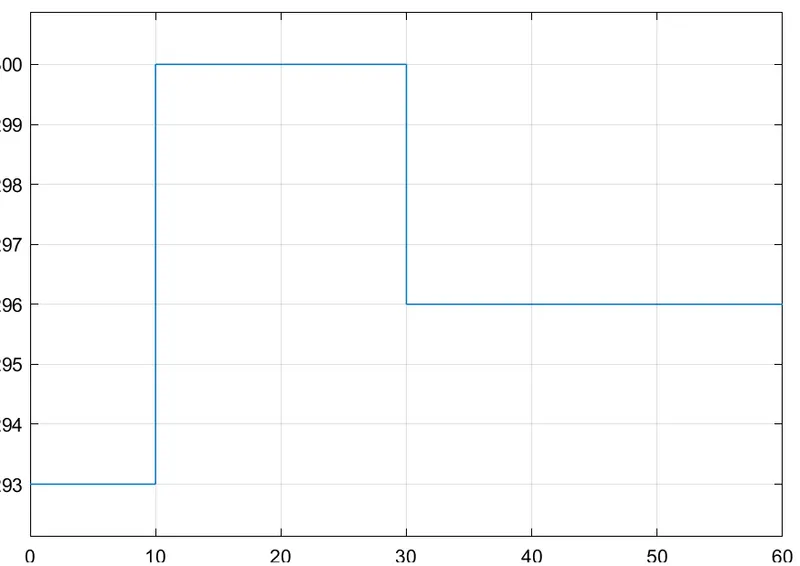
fig 2. Voltage(v) vs Time (data output from the voltage sensor)
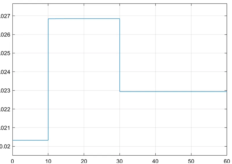
Fig 3. Switch output vs time (data output from the switch)
**** 1 represents the on state and 0 represents the off state.
Conclusion
A model is made according to the conditions using the thermistor to control the temperature of the system. As we can obseve a surge in the temperature and voltage in the fig 1 and fig 2. As a result we can see the state of switch is changing in the fig .3. If we connected a fan on to the switch output, it will turn on and off according to the above condition.