Advanced Sheet Metal Design Using NX Cad Challenge_1_Casing Design
Advanced sheet metal design using NX CAD.
Challenge 1 – Casing design.
Objective.
To design a sheet metal casing as per the data given in NX CAD.
Introduction.
In this challenge, a sheet metal casing is designed using the NX Cad software. NX CAD provides the tools and environment to design sheet metal components and many other designs. Through this challenge we are aiming to explore several tools in NX CAD for sheet metal design, such as:
- Tabs
- Flanges
- Cut-outs
- Break corner
- Holes
- Bending
- Unbending
- Dimples
- Beads
- Flat pattern
Design methodology
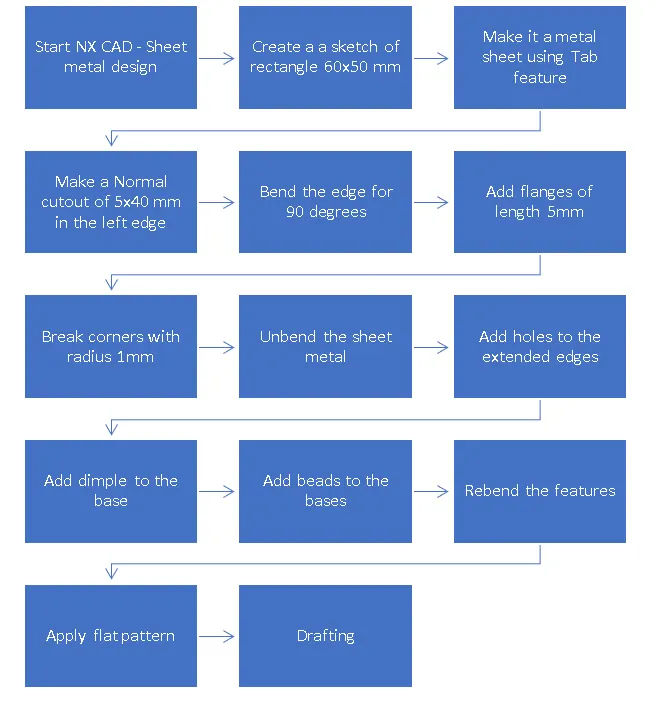
Description
STEP 1
First create a sketch and make a rectangle of dimension 50x60 mm
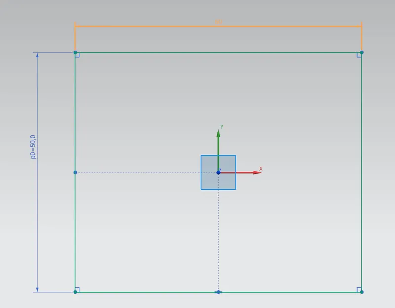
STEP 2
Then by using the tab tool convert the sketch in to a metal sheet
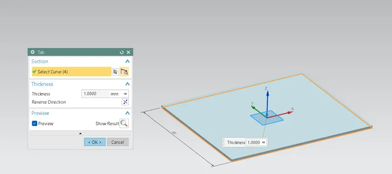
STEP 3
Then create a new sketch on the XY plane and create another rectangle on the edge of the base rectangle as show in the picture
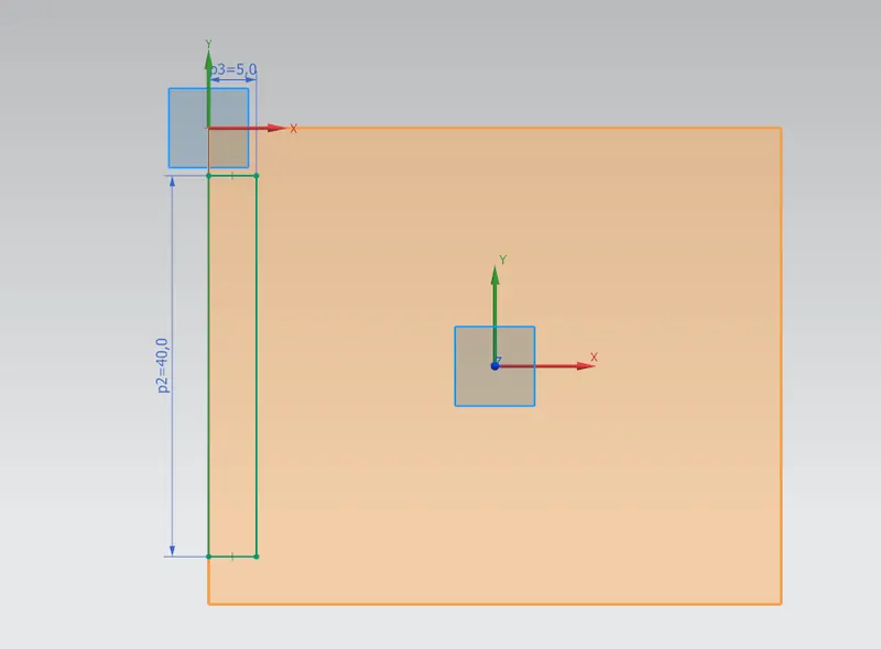
STEP 4
Then by using the normal cut-out tool, cut the base by selecting the second rectangle as the cutting curve.
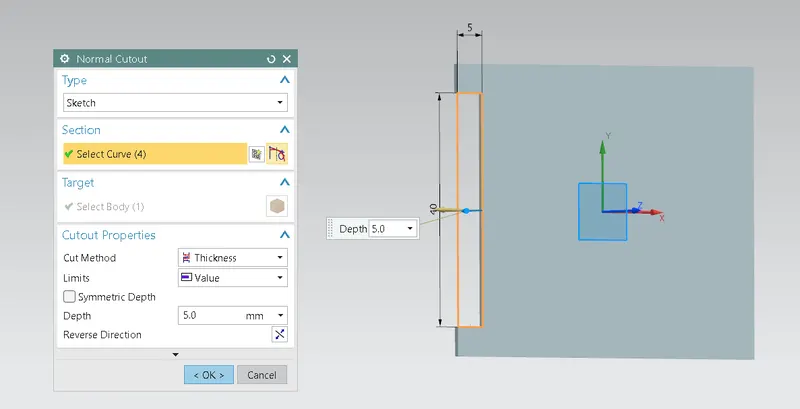
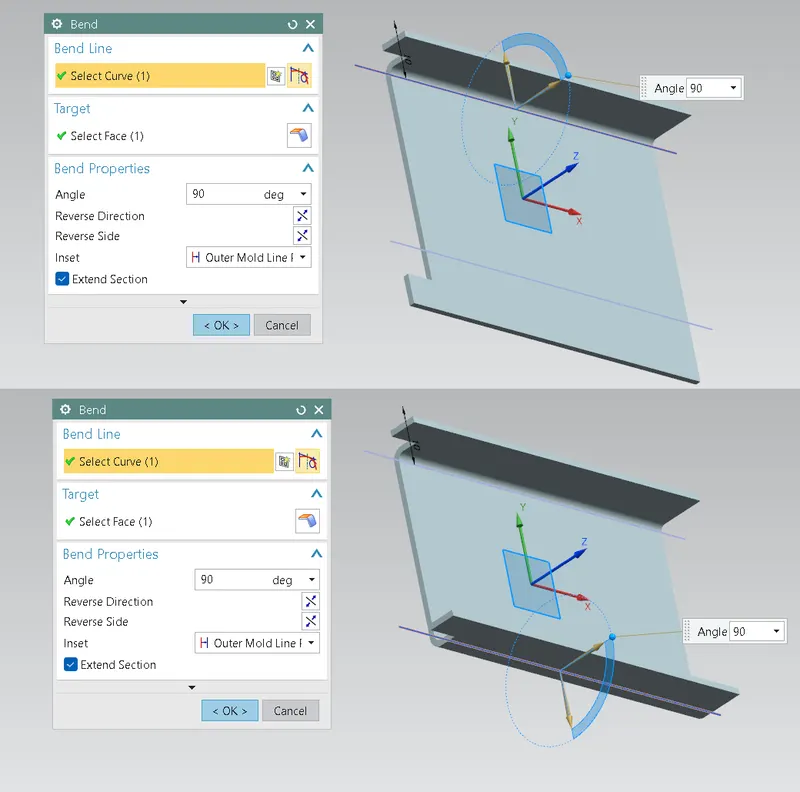
STEP 5
Now on the XY plane create two symmetric lines which are located at 10 mm from the top. Then using that as reference curve, bend the base as shown in the picture.
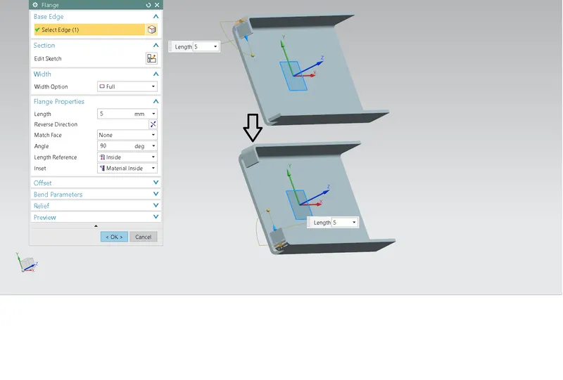
STEP 6
After bending make flange on the cut-out edges with 5mm length
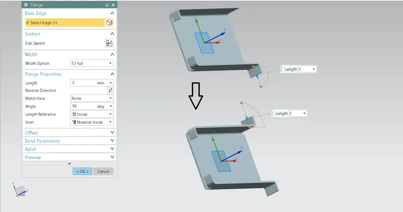
STEP 7
Do the same on the other end also with a 5mm length
STEP 8
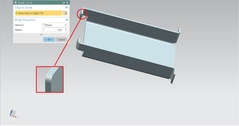
Then get rid of the sharp edges in the feature for easy machining by using the break corner tool.
STEP 9
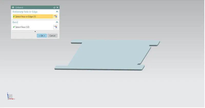
Now unbend the feature using the unbend tool by selecting the base as the stationary face.
STEP 10
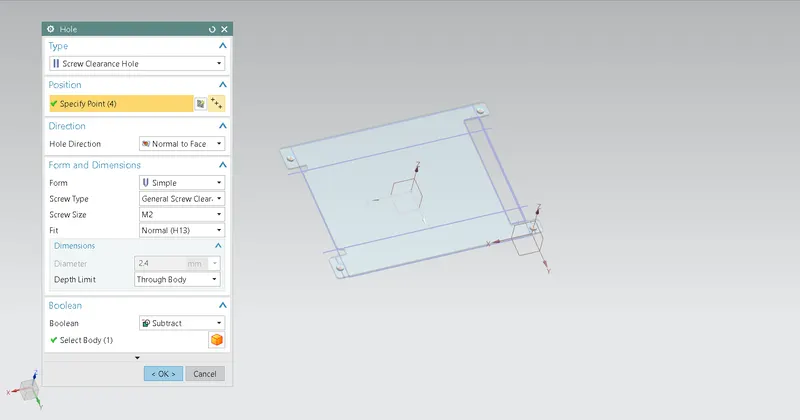
Now for making holes on the flange, draw reference points on the centre of the flanges by drawing a line first in the flange then marking its midpoint. Then taking those points as reference, create holes using hole tool. Select screw clearance holes as type, screw size as M2, fit as Normal(H13), and the depth option as through body.
STEP 11
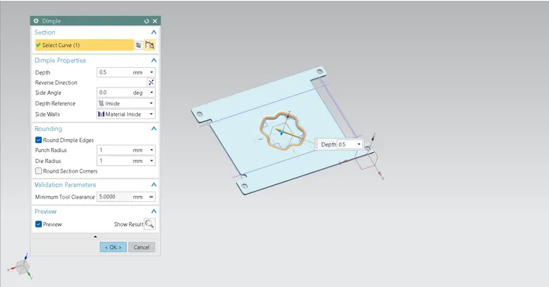
Now for creating the dimple first create the reference sketch.
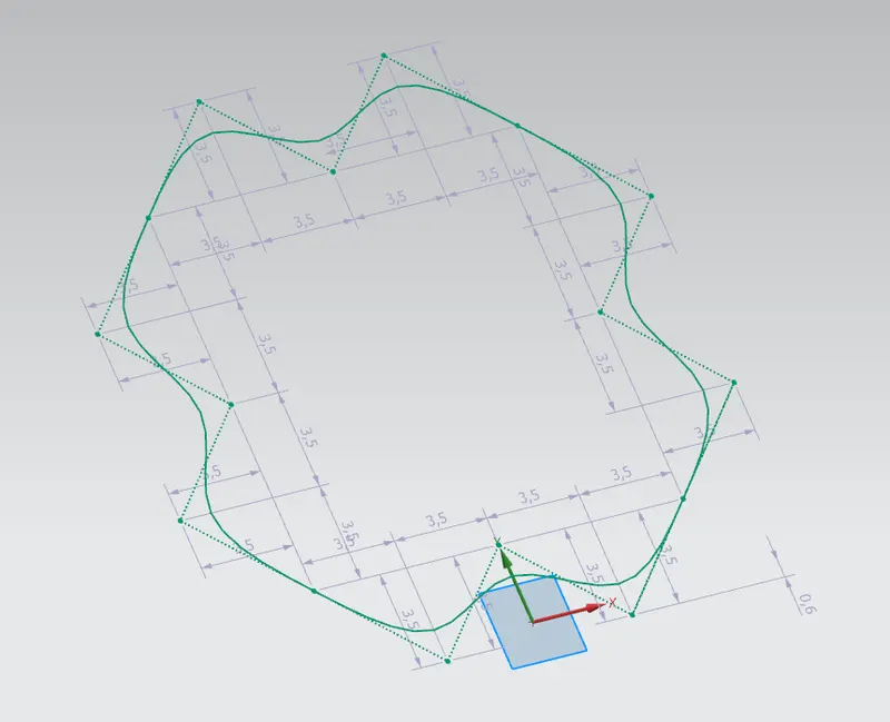
For creating the reference sketch first create a cross shaped sketch where each half side is 5mm in length. The using the studio spline tool make spline curve by selecting the cross’s edges as the poles. Then using the move curve tool rotate the spline 45 degrees by keeping the origin as (0,0,0,). Then add the dimple to the base by selecting the spline curve as the reference. Keep the depth as half of the base thickness and keep the punch and the die radius as 1mm.
STEP 12
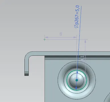
Now create another sketch as shown in the picture on the XY plane for creating the beads.
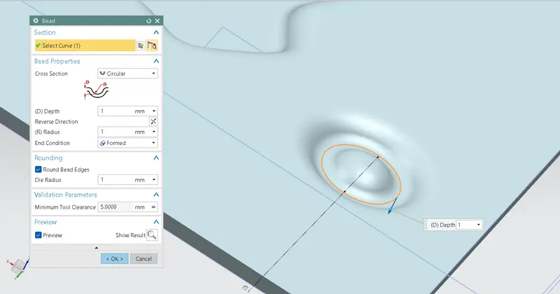
After making one bead, copy to other locations using the mirror tool by selecting appropriate planes.
STEP 13
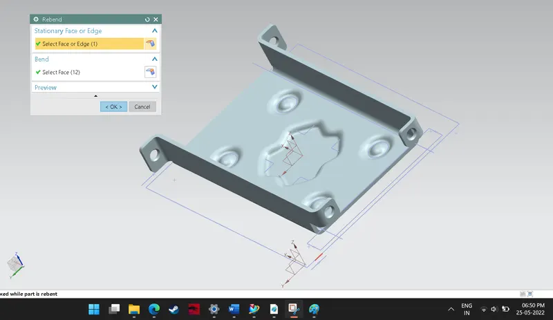
Re-bend the feature in the reverse order where we unbend the feature.
STEP 14
Finally flatten the feature by flat pattern tool.
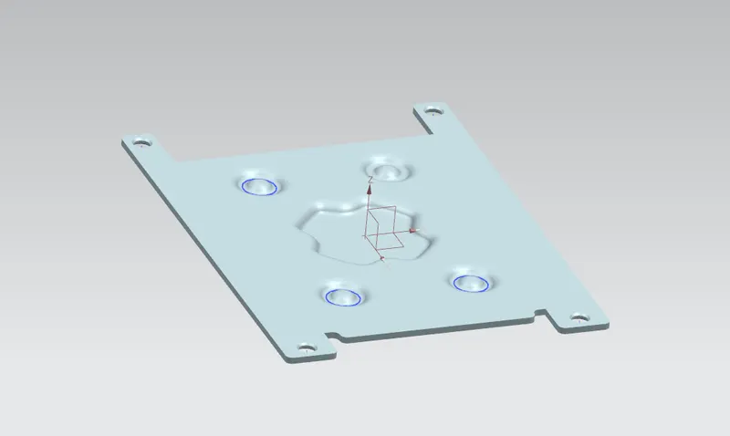
FRONT VIEW
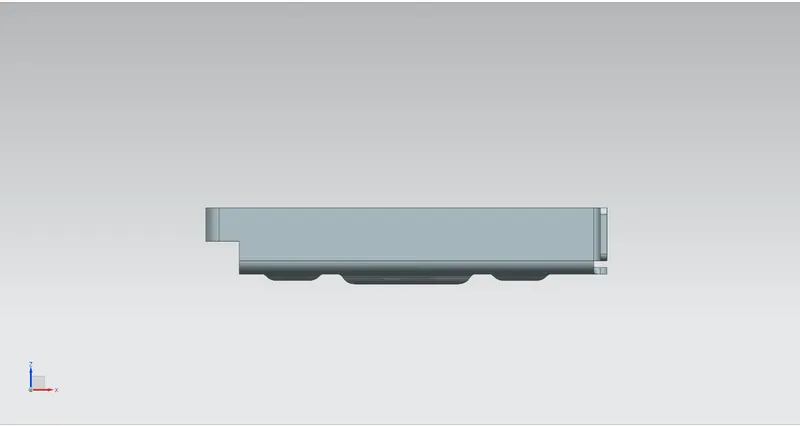
SIDE VIEW
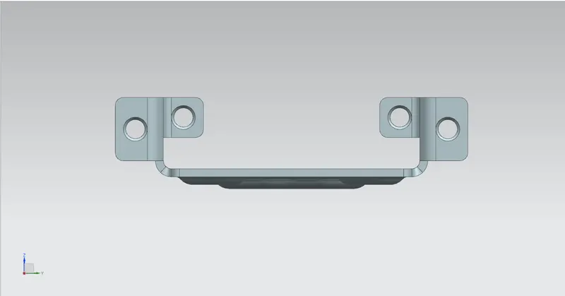
TOP VIEW
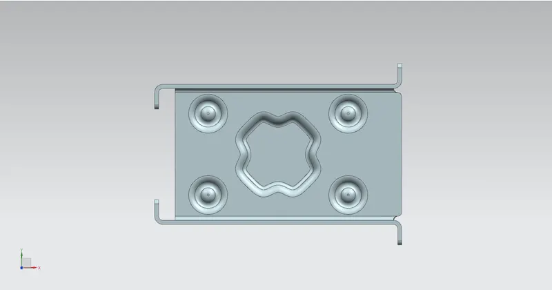
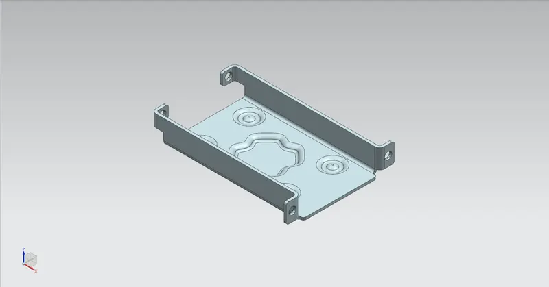
ISOMETRIC VIEW
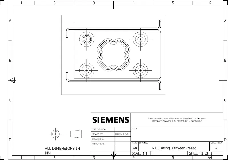
DRAFT
Conclusion
The feature has been created as per the requirement with NX CAD and the flat pattern is created for the making the product.