Switch Bezel Design
AIM
- To create the Switch Bezel Plastic component through the given Class-A surface.
- The tooling axis for the given Class-A Surface should be created meeting the requirements of the draft angle and at the end perform the Draft analysis on the model.
- A solid part should be created out of the closed surface with a thickness of 2.5 mm
PROCEDURE
STEP 1
Load up the given model in the Catia workbench.
STEP 2
Tooling Axis
- First decide the tooling axis direction , here we have only 3 surface. So using sketches, the tooling axis is made.
- Base surface is extracted initially (fig.1), then created a point over it at its center. Then an axis sytem is created on it. (fig.2)
- Then create a positioned sketch on YZ plane.
- Take an intersection of class A. (fig.3).
- Then create two lines on the inclines over the intersection and biscet then to obtain the line. (fig.4)
- Tooling axis for X direction is created (fig.5)
fig.1
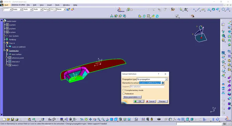
fig.2
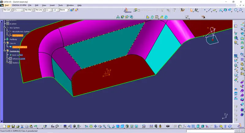
fig.3
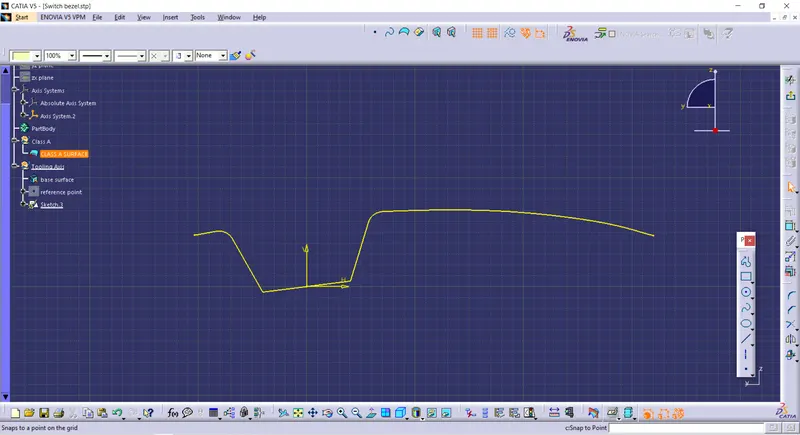
fig.4
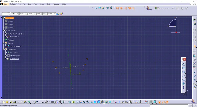
fig.5
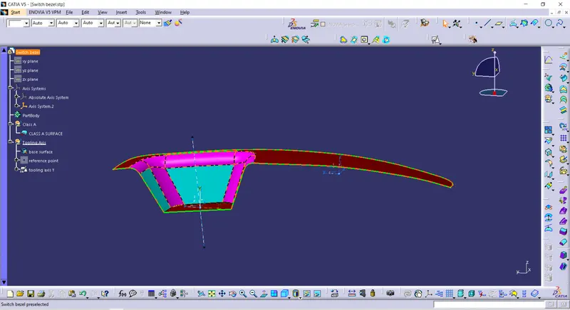
- Create another positioned sketch on ZX plane .
- Then take a section of class and intersect it. (fig.6) and (fig.7)
- Create a line over the inclined line over the intersection and create a line starting from the center and with 3 deg angle with the first line we created. (fig.8)
- Bisect both the lines to obtain the tooling axis for Y direction. (fig.9)
fig.6
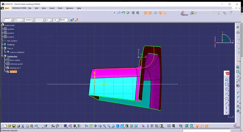
fig.7
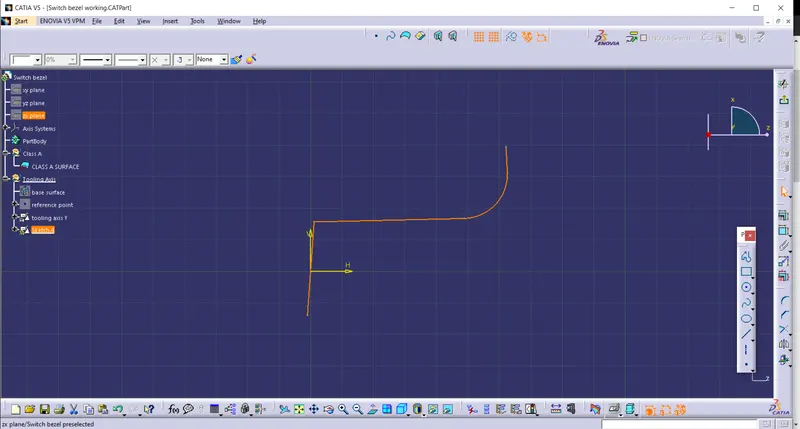
fig.8
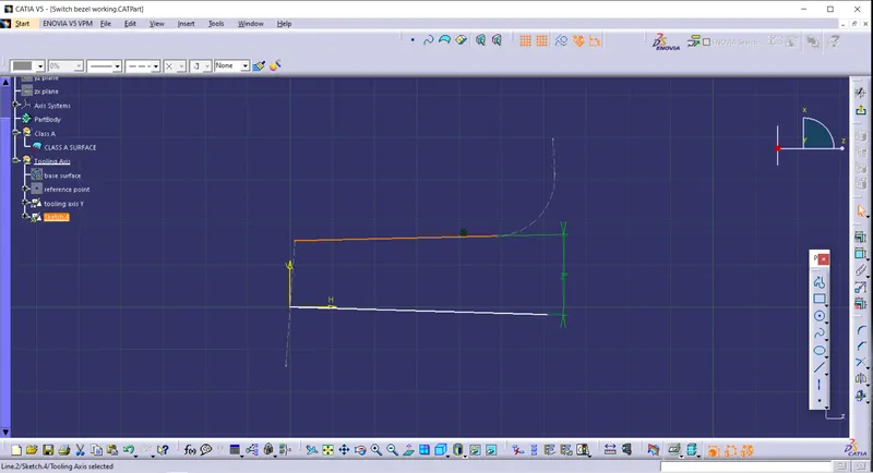
fig.9
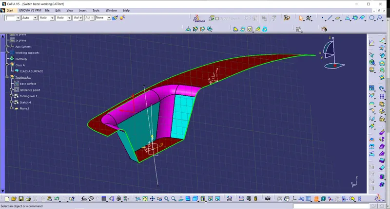
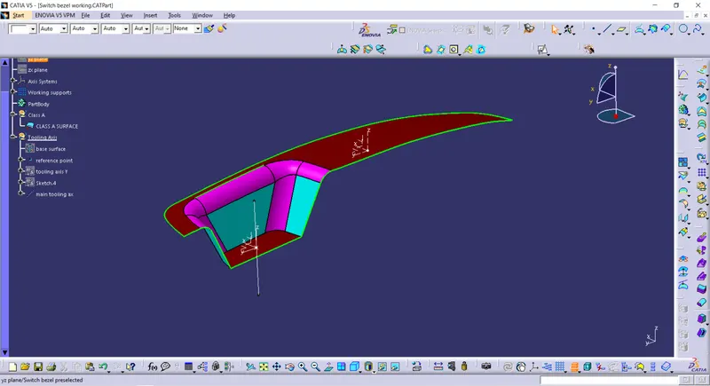
- Next, to create the main tooling axis , bisect the x and y tooling axis to create the main tooling axis. (fig.10) and (fig.11)
fig.10
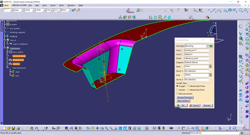
fig.11
STEP 3
CREATING THE B SURFACE.
- Simplyfy the model by untrimming the surfaces of the component and extrapolate the untrims so that the untrimmed surfaces cuts through each other. (fig.12, fig.13, fig.14)
- Create offsets of each surface with an offset value of 2.5 , which will be the thickness of final model. (fig.15)
- Then trim the untrims based off of the class A's shape.
- Then obtain a final trim of B surface (fig.16)
- finally add fillets to the B surface. (fig.17,fig.18)
fig.12
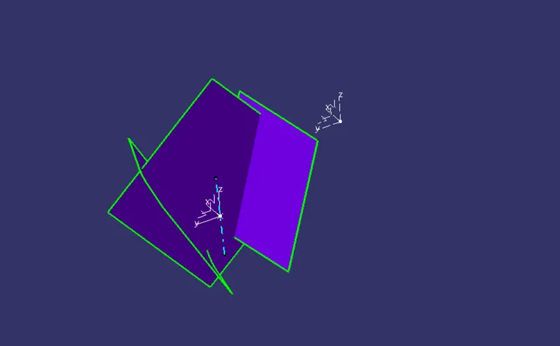
fig.13
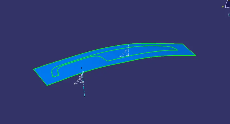
fig.14
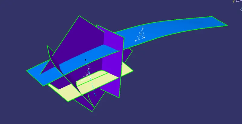
fig.15
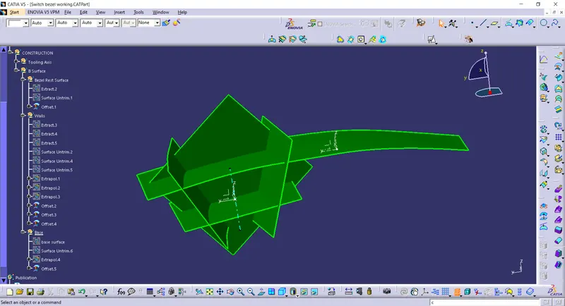
fig.16
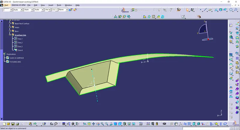
fig.17
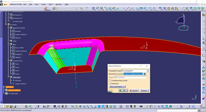
fig.18
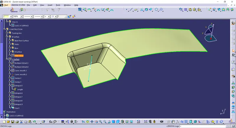
STEP 4
CREATING THE C SURFACE.
- Extract the boundaries of the class A (fig.19)
- Sweep the extracted curves as guide curve and draft axis as the tooling axis with an angle of 3 deg.(fig.20)
- Extrpolate the sweep surface and trim both the sweeps .(fig.21a)(fig.21b)
- Use smoothcurves to get rid of the patches on the sweep.
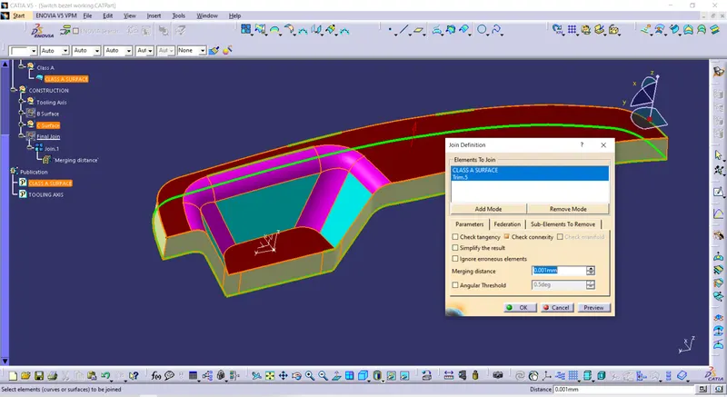
- Then join the A surface with C surface. (fig.22)
fig.19
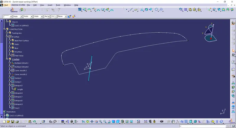
fig.20
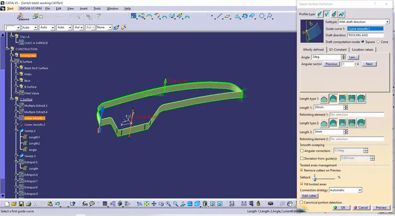
fig.21a
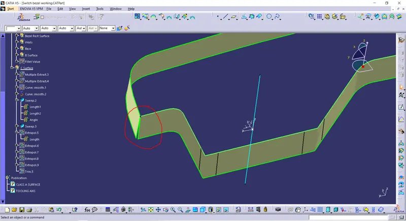
fig.21b
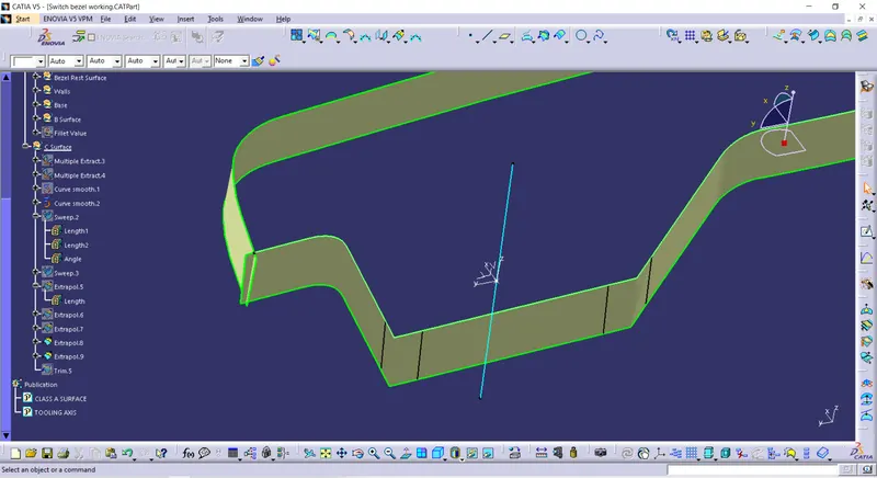
C surface
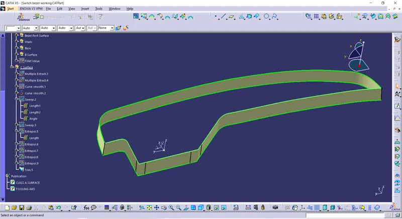
fig.22
STEP 5
FINAL CLOSE SURFACE CREATION.
- After joining the A and C surfaces , join that output with B surface. (fig.23)
- Make sure no boundary is forming after joining all the surfaces (fig.24)
- Final close surface is created .fig(25)
fig.23
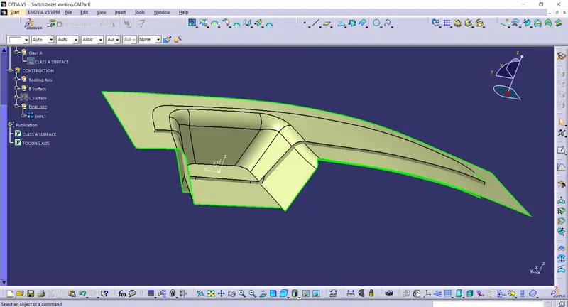
fig.24
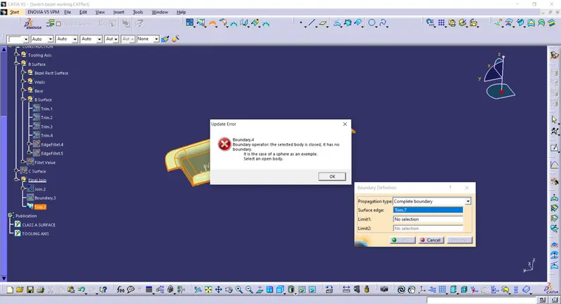
fig.25
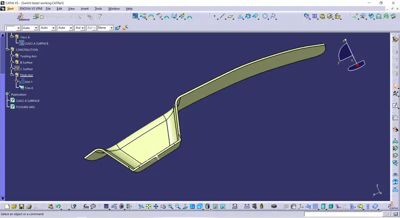
STEP 6
CLOSE BODY CREATION
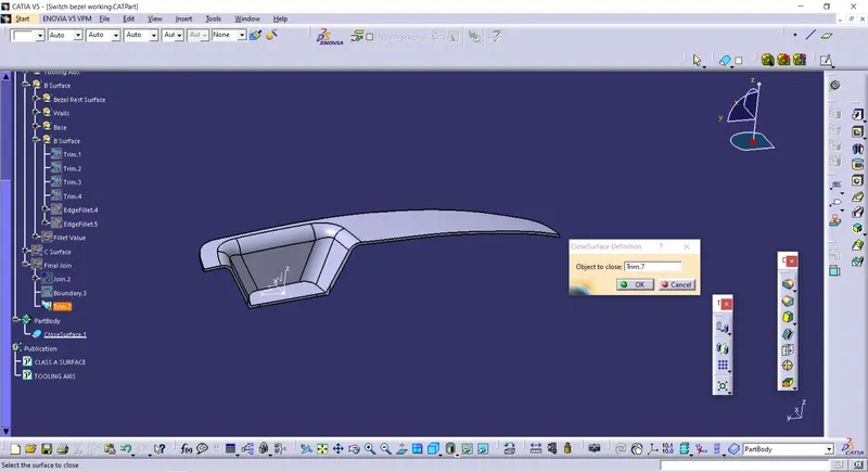
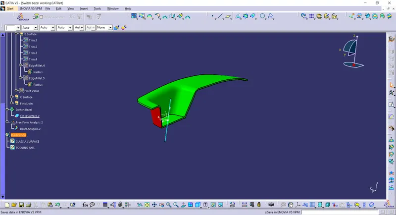
- Go to part body workbench and using close body command , thicken the component. (fig.26).
fig.26
STEP 7
DRAFT ANALYSIS
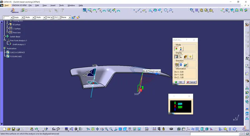
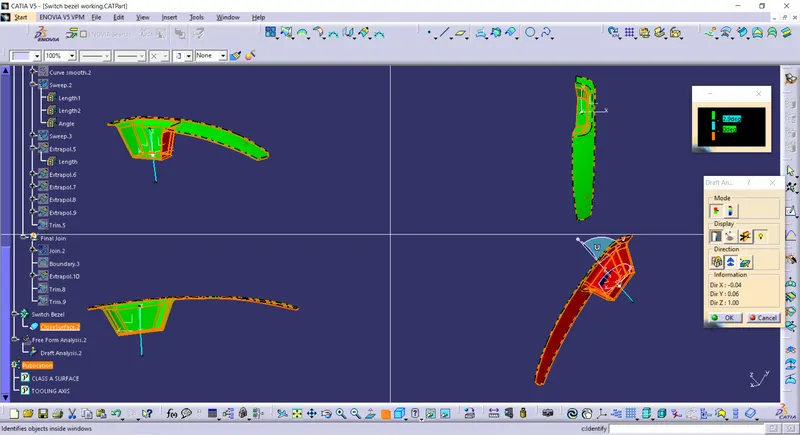
- Run draft analysis on the final output .
- Make sure the min draft angle 3 deg is followed.
RESULT
- Created the Switch Bezel Plastic component through the given Class-A surface.
- The tooling axis for the given Class-A Surface is created meeting the requirements of the draft angle and at the end perform the Draft analysis on the model.
- A solid part is created out of the closed surface with a thickness of 2.5 mm
- Ran draft analysis on the component and ensured the min 3 deg draft angle is followed.