Core & Cavity Design
Aim
To create the core and cavity blocks for the switch bezel.
Procedure
Step 1.
Import the switch bezel which we designed in the previous challenge into the catia workbench.
Step 2.
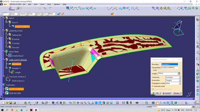
Create a new geometrical set and extrapolate the class A for about 10-15 mm
Step 3.
Check the draft analysis of the surfaces which are going to come on the core and cavity side.
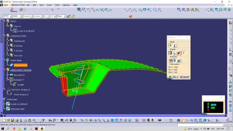
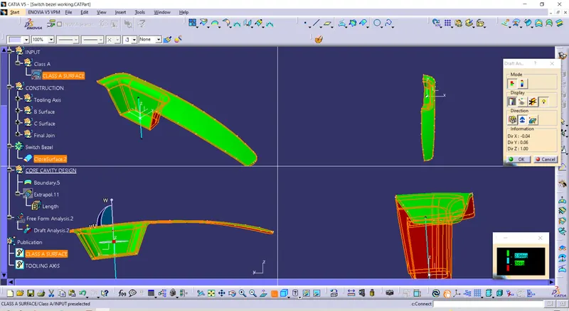
Step 4.
For making the core part, unhide the class A , class C surface and class B surface also. Then trim the class A with the C surface first. Then trim it with B surface extensions.
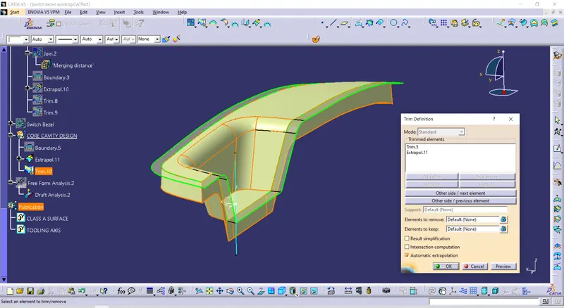
Step 5.
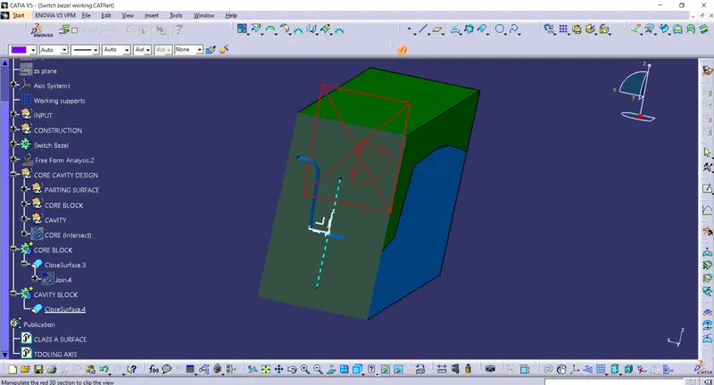
Draw a rectangle shape over the parting surface and chop it off. Make sure the class A is inside the rectangle. After that extrude it along with the tooling axis. Then trim the core along with the parting surface. Closel the open surface using the fill command. Convert the surface into a solid in part workbench.
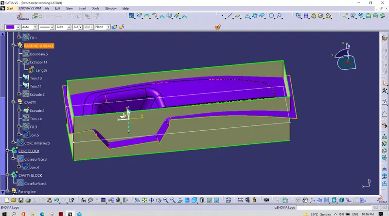
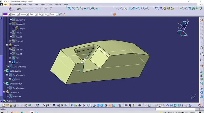
Step 6.
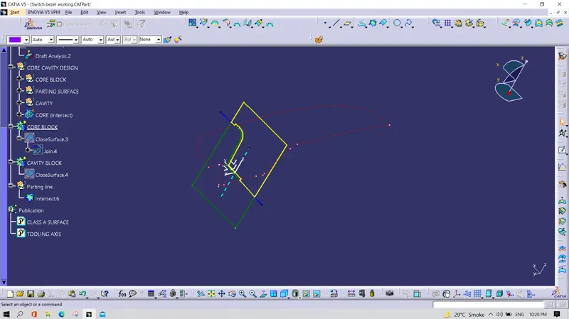
Make an intersection by intersecting the component , parting surface and the core along with the X plane. From that we can ensure the position of the parting line which has to be on the B side.
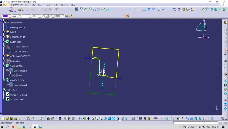
Step 7.
Create the extrude along the tooling axis . Trim it along with the B surface. Fill the close boundary and join it together. Convert it into a solid in the part workbench.
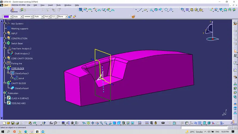
Step 8.
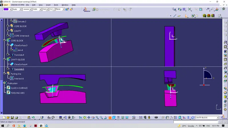
Add the cavity component to the intersection. From the intersect we can see the tooling axis and the tool direction.
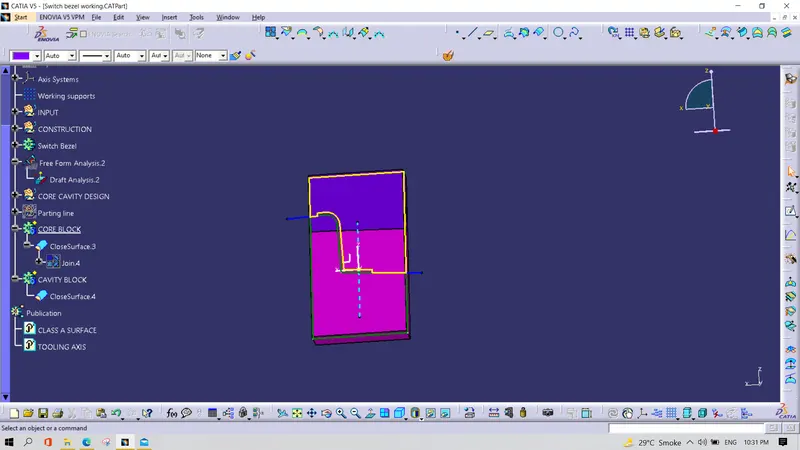
Step 9.
Finally intersect the ClassA and C join with B surface to view the parting line.